Page 1630 of 2493
SAT396D
c. While holding anchor end pin, tighten lock nut.
SAT397D
11. Apply compressed air to oil holes of transmission case and
check operation of brake band.
SAT030D
Assembly (4)NJAT01781. Install final drive assembly on transmission case.
SAT033DA
2. Install oil tube on converter housing.
ASSEMBLY
Assembly (3) (Cont'd)
AT-444
Page 1631 of 2493
SAT405D
3. Install O-ring on differential oil port of transmission case.
4. Install converter housing on transmission case.
+Apply locking sealant to mating surface of converter
housing.
Bolt Length mm (in)
A32.8 (1.291)
B40 (1.57)
SAT406DA
5. Install accumulator piston.
a. Check contact surface of accumulator piston for damage.
SAT407DA
b. Install O-rings on accumulator piston.
+Apply ATF to O-rings.
Accumulator piston O-rings:
Refer to SDS, AT-457.
SAT878J
c. Install accumulator pistons and return springs on transmission
case.
+Apply ATF to inner surface of transmission case.
Return springs:
Refer to SDS, AT-457.
ASSEMBLY
Assembly (4) (Cont'd)
AT-445
Page 1634 of 2493
SAT426DB
d. Usea4mm(0.157 in) pin for this adjustment.
1) Insert the pin straight into the manual shaft adjustment hole.
2) Rotate PNP switch until the pin can also be inserted straight
into hole in PNP switch.
e. Tighten PNP switch fixing bolts.
f. Remove pin from adjustment hole after adjusting PNP switch.
SAT586H
10. Install oil charging pipe and oil cooler tube to transmission
case.
SAT428DA
11. Install torque converter.
a. Pour ATF into torque converter.
+Approximately 1 liter (7/8 Imp qt) of fluid is required for a
new torque converter.
+When reusing old torque converter, add the same amount
of fluid as was drained.
SAT429D
b. Install torque converter while aligning notches of torque con-
verter with notches of oil pump.
SAT430D
c. Measure distance ªAº to check that torque converter is in
proper position.
Distance ªAº:
15.9 mm (0.626 in) or more
ASSEMBLY
Assembly (4) (Cont'd)
AT-448
Page 1636 of 2493

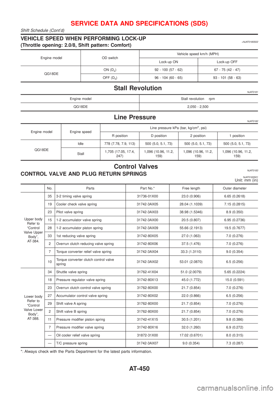
VEHICLE SPEED WHEN PERFORMING LOCK-UP=NJAT0180S02(Throttle opening: 2.0/8, Shift pattern: Comfort)
Engine model OD switchVehicle speed km/h (MPH)
Lock-up ON Lock-up OFF
QG18DEON (D
4) 92 - 100 (57 - 62) 67 - 75 (42 - 47)
OFF (D
3) 96 - 104 (60 - 65) 93 - 101 (58 - 63)
Stall RevolutionNJAT0181
Engine model Stall revolution rpm
QG18DE 2,050 - 2,500
Line PressureNJAT0182
Engine model Engine speedLine pressure kPa (bar, kg/cm
2, psi)
R position D position 2 position 1 position
QG18DEIdle 778 (7.78, 7.9, 113) 500 (5.0, 5.1, 73) 500 (5.0, 5.1, 73) 500 (5.0, 5.1, 73)
Stall1,705 (17.05, 17.4,
247)1,096 (10.96, 11.2,
159)1,096 (10.96, 11.2,
159)1,096 (10.96, 11.2,
159)
Control ValvesNJAT0183CONTROL VALVE AND PLUG RETURN SPRINGSNJAT0183S01Unit: mm (in)
No. Parts Part No.* Free length Outer diameter
Upper body
Refer to
ªControl
Valve Upper
Bodyº,
AT-384.35 3-2 timing valve spring 31736-01X00 23.0 (0.906) 6.65 (0.2618)
19 Cooler check valve spring 31742-3AX05 28.04 (1.1039) 7.15 (0.2815)
23 Pilot valve spring 31742-3AX03 38.98 (1.5346) 8.9 (0.350)
15 1-2 accumulator valve spring 31742-3AX00 20.5 (0.807) 6.95 (0.2736)
28 1-2 accumulator piston spring 31742-3AX09 55.66 (2.1913) 19.5 (0.7677)
33 1st reducing valve spring 31742-80X05 27.0 (1.063) 7.0 (0.276)
2 Overrun clutch reducing valve spring 31742-80X06 37.5 (1.476) 7.0 (0.276)
7 Torque converter relief valve spring 31742-3AX04 33.3 (1.3110) 9.0 (0.354)
10Torque converter clutch control valve
spring31742-3AX02 53.01 (2.0870) 6.5 (0.256)
Lower body
Refer to
ªControl
Valve Lower
Bodyº,
AT-388.34 Shuttle valve spring 31762-41X04 51.0 (2.0079) 5.65 (0.2224)
18 Pressure regulator valve spring 31742-80X13 45.0 (1.772) 15.0 (0.591)
23 Overrun clutch control valve spring 31762-80X00 21.7 (0.854) 7.0 (0.276)
27 Accumulator control valve spring 31742-80X02 22.0 (0.866) 6.5 (0.256)
29 Shift valve A spring 31762-80X00 21.7 (0.854) 7.0 (0.276)
2 Shift valve B spring 31762-80X00 21.7 (0.854) 7.0 (0.276)
11 Pressure modifier piston spring 31742-41X15 30.5 (1.201) 9.8 (0.386)
7 Pressure modifier valve spring 31742-80X16 32.0 (1.260) 6.9 (0.272)
Ð Oil cooler relief valve spring 31872-31X00 17.02 (0.6701) 8.0 (0.315)
Ð T/C pressure spring 31742-3AX07 9.0 (0.354) 7.3 (0.287)
*: Always check with the Parts Department for the latest parts information.
SERVICE DATA AND SPECIFICATIONS (SDS)
Shift Schedule (Cont'd)
AT-450
Page 1639 of 2493

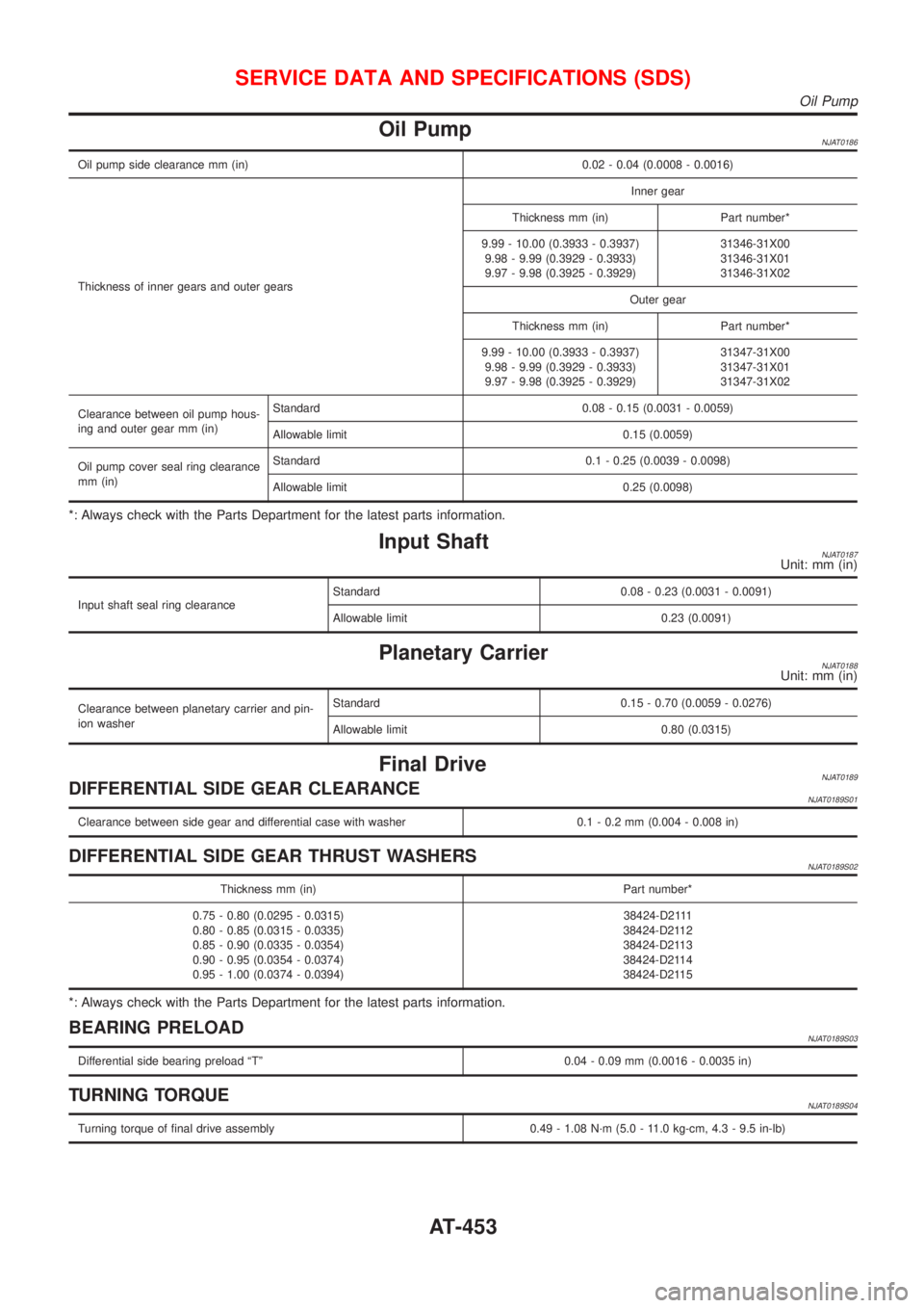
Oil PumpNJAT0186
Oil pump side clearance mm (in) 0.02 - 0.04 (0.0008 - 0.0016)
Thickness of inner gears and outer gearsInner gear
Thickness mm (in) Part number*
9.99 - 10.00 (0.3933 - 0.3937)
9.98 - 9.99 (0.3929 - 0.3933)
9.97 - 9.98 (0.3925 - 0.3929)31346-31X00
31346-31X01
31346-31X02
Outer gear
Thickness mm (in) Part number*
9.99 - 10.00 (0.3933 - 0.3937)
9.98 - 9.99 (0.3929 - 0.3933)
9.97 - 9.98 (0.3925 - 0.3929)31347-31X00
31347-31X01
31347-31X02
Clearance between oil pump hous-
ing and outer gear mm (in)Standard 0.08 - 0.15 (0.0031 - 0.0059)
Allowable limit 0.15 (0.0059)
Oil pump cover seal ring clearance
mm (in)Standard 0.1 - 0.25 (0.0039 - 0.0098)
Allowable limit 0.25 (0.0098)
*: Always check with the Parts Department for the latest parts information.
Input ShaftNJAT0187Unit: mm (in)
Input shaft seal ring clearanceStandard 0.08 - 0.23 (0.0031 - 0.0091)
Allowable limit 0.23 (0.0091)
Planetary CarrierNJAT0188Unit: mm (in)
Clearance between planetary carrier and pin-
ion washerStandard 0.15 - 0.70 (0.0059 - 0.0276)
Allowable limit 0.80 (0.0315)
Final DriveNJAT0189DIFFERENTIAL SIDE GEAR CLEARANCENJAT0189S01
Clearance between side gear and differential case with washer 0.1 - 0.2 mm (0.004 - 0.008 in)
DIFFERENTIAL SIDE GEAR THRUST WASHERSNJAT0189S02
Thickness mm (in) Part number*
0.75 - 0.80 (0.0295 - 0.0315)
0.80 - 0.85 (0.0315 - 0.0335)
0.85 - 0.90 (0.0335 - 0.0354)
0.90 - 0.95 (0.0354 - 0.0374)
0.95 - 1.00 (0.0374 - 0.0394)38424-D2111
38424-D2112
38424-D2113
38424-D2114
38424-D2115
*: Always check with the Parts Department for the latest parts information.
BEARING PRELOADNJAT0189S03
Differential side bearing preload ªTº 0.04 - 0.09 mm (0.0016 - 0.0035 in)
TURNING TORQUENJAT0189S04
Turning torque of final drive assembly 0.49 - 1.08 N´m (5.0 - 11.0 kg-cm, 4.3 - 9.5 in-lb)
SERVICE DATA AND SPECIFICATIONS (SDS)
Oil Pump
AT-453
Page 1646 of 2493
SBR686C
Precautions
PRECAUTIONSNJAX0001+When installing rubber parts, final tightening must be car-
ried out under unladen condition* with tires on ground.
*: Fuel, radiator coolant and engine oil full. Spare tire, jack,
hand tools and mats in designated positions.
+After installing removed suspension parts, check wheel
alignment and adjust if necessary.
+Use flare nut wrench when removing or installing brake
tubes.
+Always torque brake lines when installing.
Preparation
SPECIAL SERVICE TOOLSNJAX0002
Tool number
Tool nameDescription
HT72520000
Ball joint remover
NT146
Removing tie-rod outer end and lower ball joint
KV38106800
Differential side oil seal
protector
NT147
Installing drive shaft
KV38106800
COMMERCIAL SERVICE TOOLSNJAX0003
Tool name Description
1 Flare nut crowfoot
2 Torque wrench
NT360
Removing and installing each brake piping
a: 10 mm (0.39 in)
FRONT AXLE
Precautions
AX-2
Page 1651 of 2493

SFA114A
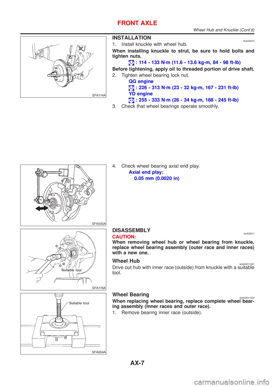
INSTALLATIONNJAX00101. Install knuckle with wheel hub.
When installing knuckle to strut, be sure to hold bolts and
tighten nuts.
: 114 - 133 N´m (11.6 - 13.6 kg-m, 84 - 98 ft-lb)
Before tightening, apply oil to threaded portion of drive shaft.
2. Tighten wheel bearing lock nut.
QG engine
: 226 - 313 N´m (23 - 32 kg-m, 167 - 231 ft-lb)
YD engine
: 255 - 333 N´m (26 - 34 kg-m, 188 - 245 ft-lb)
3. Check that wheel bearings operate smoothly.
SFA543A
4. Check wheel bearing axial end play.
Axial end play:
0.05 mm (0.0020 in)
SFA116A
DISASSEMBLYNJAX0011CAUTION:
When removing wheel hub or wheel bearing from knuckle,
replace wheel bearing assembly (outer race and inner races)
with a new one.
Wheel HubNJAX0011S01Drive out hub with inner race (outside) from knuckle with a suitable
tool.
SFA654A
Wheel BearingNJAX0011S02When replacing wheel bearing, replace complete wheel bear-
ing assembly (Inner races and outer race).
1. Remove bearing inner race (outside).
FRONT AXLE
Wheel Hub and Knuckle (Cont'd)
AX-7
Page 1652 of 2493

SAX008
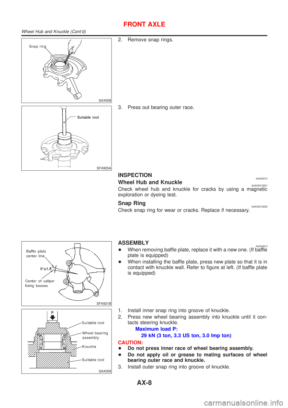
2. Remove snap rings.
SFA905A
3. Press out bearing outer race.
INSPECTIONNJAX0012Wheel Hub and KnuckleNJAX0012S01Check wheel hub and knuckle for cracks by using a magnetic
exploration or dyeing test.
Snap RingNJAX0012S02Check snap ring for wear or cracks. Replace if necessary.
SFA921B
ASSEMBLYNJAX0013+When removing baffle plate, replace it with a new one. (If baffle
plate is equipped)
+When installing the baffle plate, press new plate so that it is in
contact with knuckle wall. Refer to figure at left. (If baffle plate
is equipped)
SAX009
1. Install inner snap ring into groove of knuckle.
2. Press new wheel bearing assembly into knuckle until it con-
tacts steering knuckle.
Maximum load P:
29 kN (3 ton, 3.3 US ton, 3.0 Imp ton)
CAUTION:
+Do not press inner race of wheel bearing assembly.
+Do not apply oil or grease to mating surfaces of wheel
bearing outer race and knuckle.
3. Install outer snap ring into groove of knuckle.
FRONT AXLE
Wheel Hub and Knuckle (Cont'd)
AX-8