2001 NISSAN ALMERA N16 width
[x] Cancel search: widthPage 381 of 2493
![NISSAN ALMERA N16 2001 Electronic Repair Manual Freeze frame data
item*Description
ENGINE SPEED
[rpm]+The engine speed at the moment a malfunction is detected is displayed.
VEHICL SPEED
[km/h] or [mph]+The vehicle speed at the moment a malfunction NISSAN ALMERA N16 2001 Electronic Repair Manual Freeze frame data
item*Description
ENGINE SPEED
[rpm]+The engine speed at the moment a malfunction is detected is displayed.
VEHICL SPEED
[km/h] or [mph]+The vehicle speed at the moment a malfunction](/manual-img/5/57351/w960_57351-380.png)
Freeze frame data
item*Description
ENGINE SPEED
[rpm]+The engine speed at the moment a malfunction is detected is displayed.
VEHICL SPEED
[km/h] or [mph]+The vehicle speed at the moment a malfunction is detected is displayed.
ABSOL TH´P/S [%]+The throttle valve opening angle at the moment a malfunction is detected is displayed.
B/FUEL SCHDL
[msec]+The base fuel schedule at the moment a malfunction is detected is displayed.
INT/A TEMP SE [ÉC]
or [ÉF]+The intake air temperature at the moment a malfunction is detected is displayed.
*: The items are the same as those of 1st trip freeze frame data.
DATA MONITOR MODENJEC0034S06
Monitored item [Unit]ECM
input
signalsMain
signalsDescription Remarks
ENG SPEED [rpm]jj+Indicates the engine speed computed from
the POS signal of the crankshaft position
sensor.+Accuracy becomes poor if engine
speed drops below the idle rpm.
+If the signal is interrupted while the
engine is running, an abnormal
value may be indicated.
MAS A/F SE-B1 [V]jj+The signal voltage of the mass air flow sen-
sor is displayed.+When the engine is stopped, a cer-
tain value is indicated.
B/FUEL SCHDL
[msec]+ªBase fuel scheduleº indicates the fuel
injection pulse width programmed into
ECM, prior to any learned on board correc-
tion.
A/F ALPHA-B1 [%]j+Indicates the mean value of the air-fuel
ratio feedback correction factor per cycle.+When the engine is stopped, a cer-
tain value is indicated.
+This data also includes the data for
the air-fuel ratio learning control.
COOLAN TEMP/S
[ÉC] or [ÉF]jj+The engine coolant temperature (deter-
mined by the signal voltage of the engine
coolant temperature sensor) is displayed.+When the engine coolant tempera-
ture sensor is open or short-
circuited, ECM enters fail-safe
mode. The engine coolant tempera-
ture determined by the ECM is dis-
played.
HO2S1 (B1) [V]jj+The signal voltage of the heated oxygen
sensor 1 (front) is displayed.
HO2S2 (B1) [V]j+The signal voltage of the heated oxygen
sensor 2 (rear) is displayed.
HO2S1 MNTR (B1)
[RICH/LEAN]j+Display of heated oxygen sensor 1 (front)
signal during air-fuel ratio feedback control:
RICH ... means the mixture became ªrichº,
and control is being affected toward a
leaner mixture.
LEAN ... means the mixture became ªleanº,
and control is being affected toward a rich
mixture.+After turning ON the ignition switch,
ªRICHº is displayed until air-fuel
mixture ratio feedback control
begins.
+When the air-fuel ratio feedback is
clamped, the value just before the
clamping is displayed continuously.
ON BOARD DIAGNOSTIC SYSTEM DESCRIPTIONQG
CONSULT-II (Cont'd)
EC-85
Page 382 of 2493
![NISSAN ALMERA N16 2001 Electronic Repair Manual Monitored item [Unit]ECM
input
signalsMain
signalsDescription Remarks
HO2S2 MNTR (B1)
[RICH/LEAN]j+Display of heated oxygen sensor 2 (rear)
signal:
RICH ... means the amount of oxygen after
three way NISSAN ALMERA N16 2001 Electronic Repair Manual Monitored item [Unit]ECM
input
signalsMain
signalsDescription Remarks
HO2S2 MNTR (B1)
[RICH/LEAN]j+Display of heated oxygen sensor 2 (rear)
signal:
RICH ... means the amount of oxygen after
three way](/manual-img/5/57351/w960_57351-381.png)
Monitored item [Unit]ECM
input
signalsMain
signalsDescription Remarks
HO2S2 MNTR (B1)
[RICH/LEAN]j+Display of heated oxygen sensor 2 (rear)
signal:
RICH ... means the amount of oxygen after
three way catalyst is relatively small.
LEAN ... means the amount of oxygen after
three way catalyst is relatively large.+When the engine is stopped, a cer-
tain value is indicated.
VHCL SPEED SE
[km/h] or [mph]jj+The vehicle speed computed from the
vehicle speed sensor signal is displayed.
BATTERY VOLT [V]j+The power supply voltage of ECM is dis-
played.
THRTL POS SEN [V]jj+The throttle position sensor signal voltage is
displayed.
FUEL T/TMP SE
[ÉC] or [ÉF]*+The fuel temperature judged from the fuel
tank temperature sensor signal voltage is
displayed.
INT/A TEMP SE
[ÉC] or [ÉF]j+The intake air temperature determined by
the signal voltage of the intake air tempera-
ture sensor is indicated.
EGR TEMP SEN [V]*jj+The signal voltage of the EGR temperature
sensor is displayed.
START SIGNAL
[ON/OFF]jj+Indicates [ON/OFF] condition from the
starter signal.+After starting the engine, [OFF] is
displayed regardless of the starter
signal.
CLSD THL POS
[ON/OFF]jj+Indicates idle position [ON/OFF] computed
by ECM according to the throttle position
sensor signal.
CLSD THL/P SW
[ON/OFF]*j+Indicates mechanical contact [ON/OFF]
condition of the closed throttle position
switch.
AIR COND SIG
[ON/OFF]jj+Indicates [ON/OFF] condition of the air con-
ditioner switch as determined by the air
conditioning signal.
P/N POSI SW
[ON/OFF]jj+Indicates [ON/OFF] condition from the PNP
switch signal.
PW/ST SIGNAL
[ON/OFF]jj+Indicates [ON/OFF] condition of the power
steering oil pressure switch determined by
the power steering oil pressure switch sig-
nal.
LOAD SIGNAL
[ON/OFF]jj+Indicates [ON/OFF] condition from the elec-
trical load signal and/or lighting switch.
ON ... rear defogger is operating and/or
lighting switch is on.
OFF ... rear defogger is not operating and
lighting switch is not on.
IGNITION SW
[ON/OFF]j+Indicates [ON/OFF] condition from ignition
switch.
HEATER FAN SW
[ON/OFF]j+Indicates [ON/OFF] condition from the
heater fan switch.
INJ PULSE-B1
[msec]j+Indicates the actual fuel injection pulse
width compensated by ECM according to
the input signals.+When the engine is stopped, a cer-
tain computed value is indicated.
ON BOARD DIAGNOSTIC SYSTEM DESCRIPTIONQG
CONSULT-II (Cont'd)
EC-86
Page 384 of 2493
![NISSAN ALMERA N16 2001 Electronic Repair Manual Monitored item [Unit]ECM
input
signalsMain
signalsDescription Remarks
IDL A/V LEARN+Display the condition of idle air volume
learning
YET ... Idle air volume learning has not
been performed yet.
CMPLT NISSAN ALMERA N16 2001 Electronic Repair Manual Monitored item [Unit]ECM
input
signalsMain
signalsDescription Remarks
IDL A/V LEARN+Display the condition of idle air volume
learning
YET ... Idle air volume learning has not
been performed yet.
CMPLT](/manual-img/5/57351/w960_57351-383.png)
Monitored item [Unit]ECM
input
signalsMain
signalsDescription Remarks
IDL A/V LEARN+Display the condition of idle air volume
learning
YET ... Idle air volume learning has not
been performed yet.
CMPLT ... Idle air volume learning has
already been performed successfully.
INCMP ... Idle air volume learning has not
been performed successfully.
TRVL AFTER MIL
[km] or [Mile]+Distance traveled while MI is activated
VOLTAGE [V]+Voltage measured by the voltage probe.
PULSE
[msec] or [Hz] or [%]+Pulse width, frequency or duty cycle mea-
sured by the pulse probe.+Only ª#º is displayed if item is
unable to be measured.
+Figures with ª#ºs are temporary
ones. They are the same figures as
an actual piece of data which was
just previously measured.
*: If so equipped
NOTE:
Any monitored item that does not match the vehicle being diagnosed is deleted from the display automatically.
DATA MONITOR (SPEC) MODENJEC0034S11
Monitored item [Unit]ECM
input
signalsMain
signalsDescription Remarks
MAS A/F SE-B1 [V]jj+The signal voltage of the mass air flow sen-
sor specification is displayed.+When the engine is running, speci-
fication range is indicated.
B/FUEL SCHDL
[msec]+ªBase fuel scheduleº indicates the fuel
injection pulse width programmed into
ECM, prior to any learned on board correc-
tion.+When the engine is running, speci-
fication range is indicated.
A/F ALPHA-B1 [%]j+Indicates the mean value of the air-fuel
ratio feedback correction factor per cycle.+When the engine is running, speci-
fication range is indicated.
+This data also includes the data for
the air-fuel ratio learning control.
NOTE:
Any monitored item that does not match the vehicle being diagnosed is deleted from the display automatically.
ACTIVE TEST MODENJEC0034S07
TEST ITEM CONDITION JUDGEMENT CHECK ITEM (REMEDY)
FUEL INJECTION+Engine: Return to the original
trouble condition
+Change the amount of fuel injec-
tion using CONSULT-II.If trouble symptom disappears, see
CHECK ITEM.+Harness and connector
+Fuel injectors
+Heated oxygen sensor 1 (front)
IGNITION TIMING+Engine: Return to the original
trouble condition
+Timing light: Set
+Retard the ignition timing using
CONSULT-II.If trouble symptom disappears, see
CHECK ITEM.+ªIdle Air Volume Leaningº (Refer
to EC-55.)
+Camshaft position sensor
(PHASE)
+Crankshaft position sensor
(POS)
+Engine component parts and
installing conditions
ON BOARD DIAGNOSTIC SYSTEM DESCRIPTIONQG
CONSULT-II (Cont'd)
EC-88
Page 436 of 2493
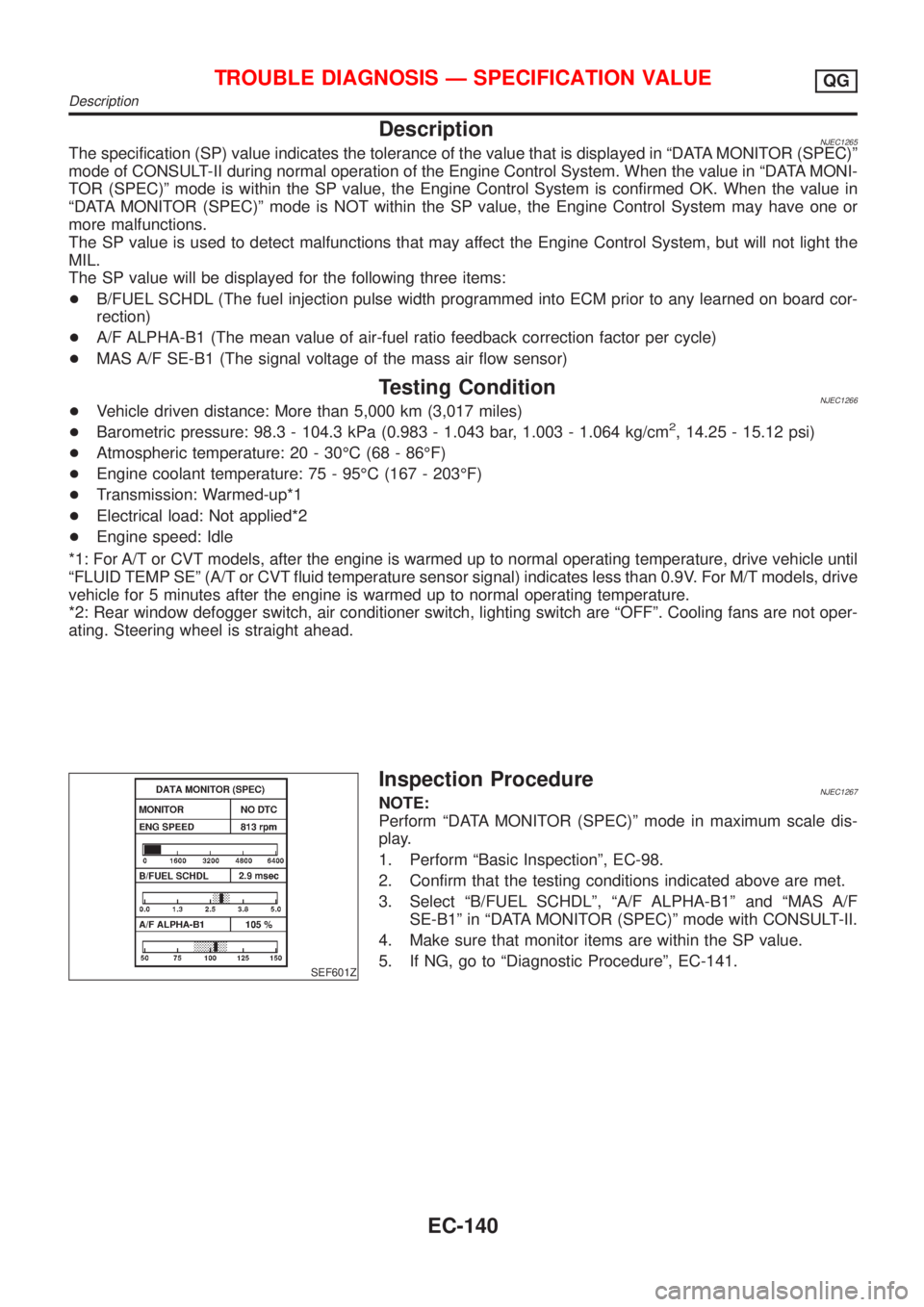
DescriptionNJEC1265The specification (SP) value indicates the tolerance of the value that is displayed in ªDATA MONITOR (SPEC)º
mode of CONSULT-II during normal operation of the Engine Control System. When the value in ªDATA MONI-
TOR (SPEC)º mode is within the SP value, the Engine Control System is confirmed OK. When the value in
ªDATA MONITOR (SPEC)º mode is NOT within the SP value, the Engine Control System may have one or
more malfunctions.
The SP value is used to detect malfunctions that may affect the Engine Control System, but will not light the
MIL.
The SP value will be displayed for the following three items:
+B/FUEL SCHDL (The fuel injection pulse width programmed into ECM prior to any learned on board cor-
rection)
+A/F ALPHA-B1 (The mean value of air-fuel ratio feedback correction factor per cycle)
+MAS A/F SE-B1 (The signal voltage of the mass air flow sensor)
Testing ConditionNJEC1266+Vehicle driven distance: More than 5,000 km (3,017 miles)
+Barometric pressure: 98.3 - 104.3 kPa (0.983 - 1.043 bar, 1.003 - 1.064 kg/cm2, 14.25 - 15.12 psi)
+Atmospheric temperature: 20 - 30ÉC (68 - 86ÉF)
+Engine coolant temperature: 75 - 95ÉC (167 - 203ÉF)
+Transmission: Warmed-up*1
+Electrical load: Not applied*2
+Engine speed: Idle
*1: For A/T or CVT models, after the engine is warmed up to normal operating temperature, drive vehicle until
ªFLUID TEMP SEº (A/T or CVT fluid temperature sensor signal) indicates less than 0.9V. For M/T models, drive
vehicle for 5 minutes after the engine is warmed up to normal operating temperature.
*2: Rear window defogger switch, air conditioner switch, lighting switch are ªOFFº. Cooling fans are not oper-
ating. Steering wheel is straight ahead.
SEF601Z
Inspection ProcedureNJEC1267NOTE:
Perform ªDATA MONITOR (SPEC)º mode in maximum scale dis-
play.
1. Perform ªBasic Inspectionº, EC-98.
2. Confirm that the testing conditions indicated above are met.
3. Select ªB/FUEL SCHDLº, ªA/F ALPHA-B1º and ªMAS A/F
SE-B1º in ªDATA MONITOR (SPEC)º mode with CONSULT-II.
4. Make sure that monitor items are within the SP value.
5. If NG, go to ªDiagnostic Procedureº, EC-141.
TROUBLE DIAGNOSIS Ð SPECIFICATION VALUEQG
Description
EC-140
Page 1131 of 2493
SMT801D
Shift Control Components
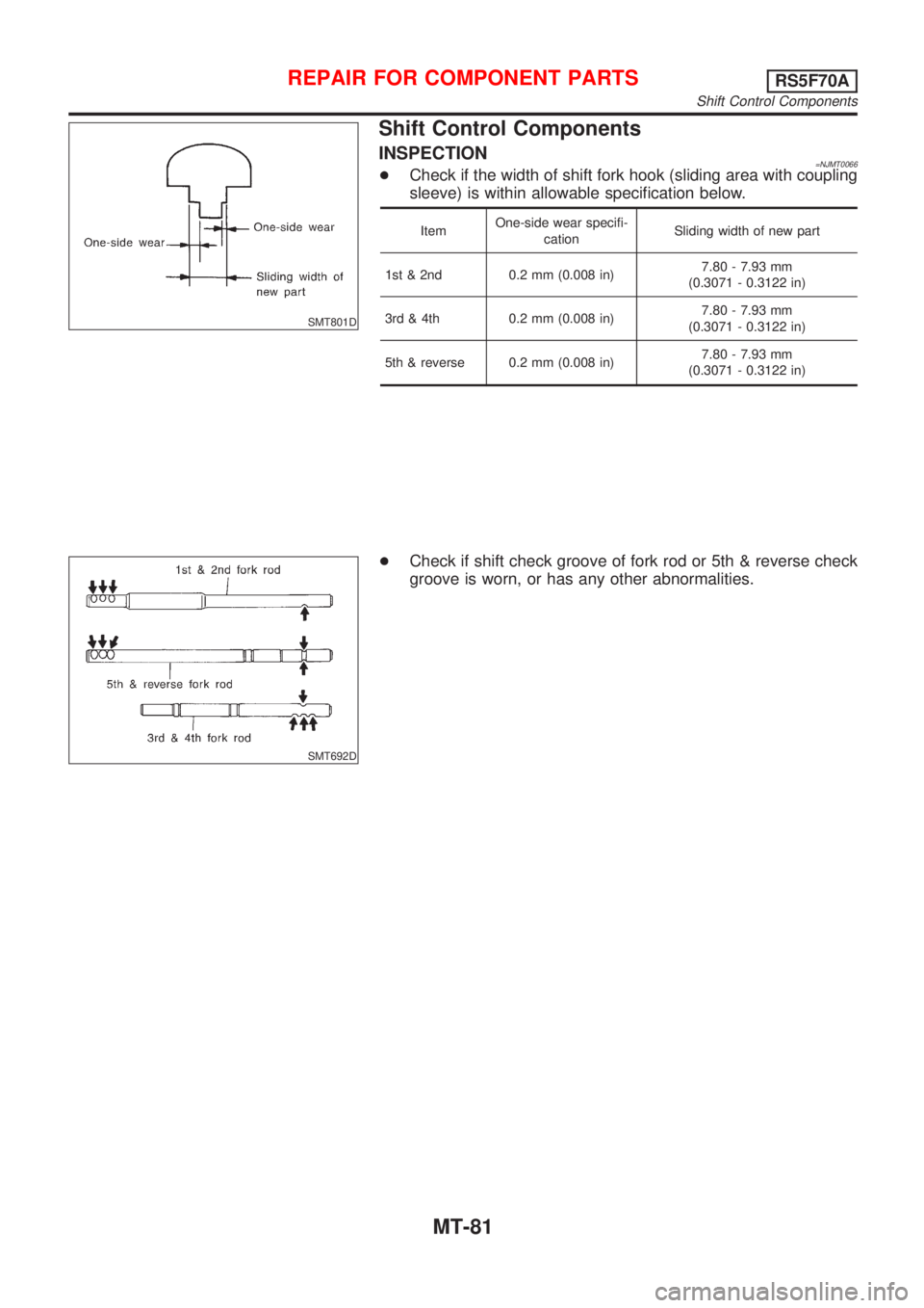
INSPECTION=NJMT0066+Check if the width of shift fork hook (sliding area with coupling
sleeve) is within allowable specification below.
ItemOne-side wear specifi-
cationSliding width of new part
1st & 2nd 0.2 mm (0.008 in)7.80 - 7.93 mm
(0.3071 - 0.3122 in)
3rd & 4th 0.2 mm (0.008 in)7.80 - 7.93 mm
(0.3071 - 0.3122 in)
5th & reverse 0.2 mm (0.008 in)7.80 - 7.93 mm
(0.3071 - 0.3122 in)
SMT692D
+Check if shift check groove of fork rod or 5th & reverse check
groove is worn, or has any other abnormalities.
REPAIR FOR COMPONENT PARTSRS5F70A
Shift Control Components
MT-81
Page 1163 of 2493
SMT644AA
2. Reinstall mainshaft rear bearing outer race without shims.
3. Clean mating surfaces of clutch housing and transmission
case with solvent.
4. Install mainshaft and mainshaft front bearing outer race into
transmission case. Turn mainshaft while holding bearing outer
race so that bearings are properly seated.
SMT078A
SMT079A
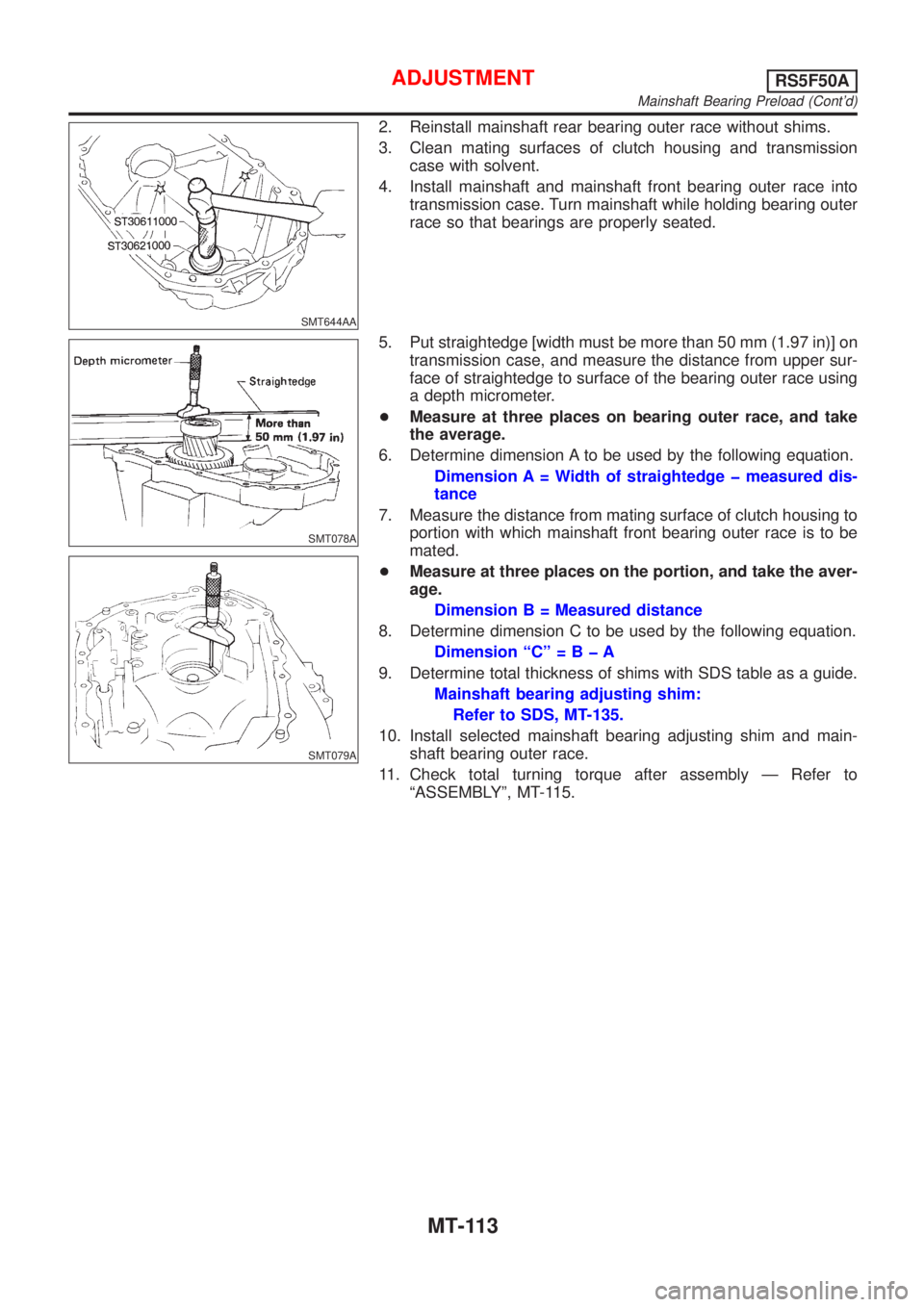
5. Put straightedge [width must be more than 50 mm (1.97 in)] on
transmission case, and measure the distance from upper sur-
face of straightedge to surface of the bearing outer race using
a depth micrometer.
+Measure at three places on bearing outer race, and take
the average.
6. Determine dimension A to be used by the following equation.
Dimension A = Width of straightedge þ measured dis-
tance
7. Measure the distance from mating surface of clutch housing to
portion with which mainshaft front bearing outer race is to be
mated.
+Measure at three places on the portion, and take the aver-
age.
Dimension B = Measured distance
8. Determine dimension C to be used by the following equation.
Dimension ªCº=BþA
9. Determine total thickness of shims with SDS table as a guide.
Mainshaft bearing adjusting shim:
Refer to SDS, MT-135.
10. Install selected mainshaft bearing adjusting shim and main-
shaft bearing outer race.
11. Check total turning torque after assembly Ð Refer to
ªASSEMBLYº, MT-115.
ADJUSTMENTRS5F50A
Mainshaft Bearing Preload (Cont'd)
MT-113
Page 1789 of 2493
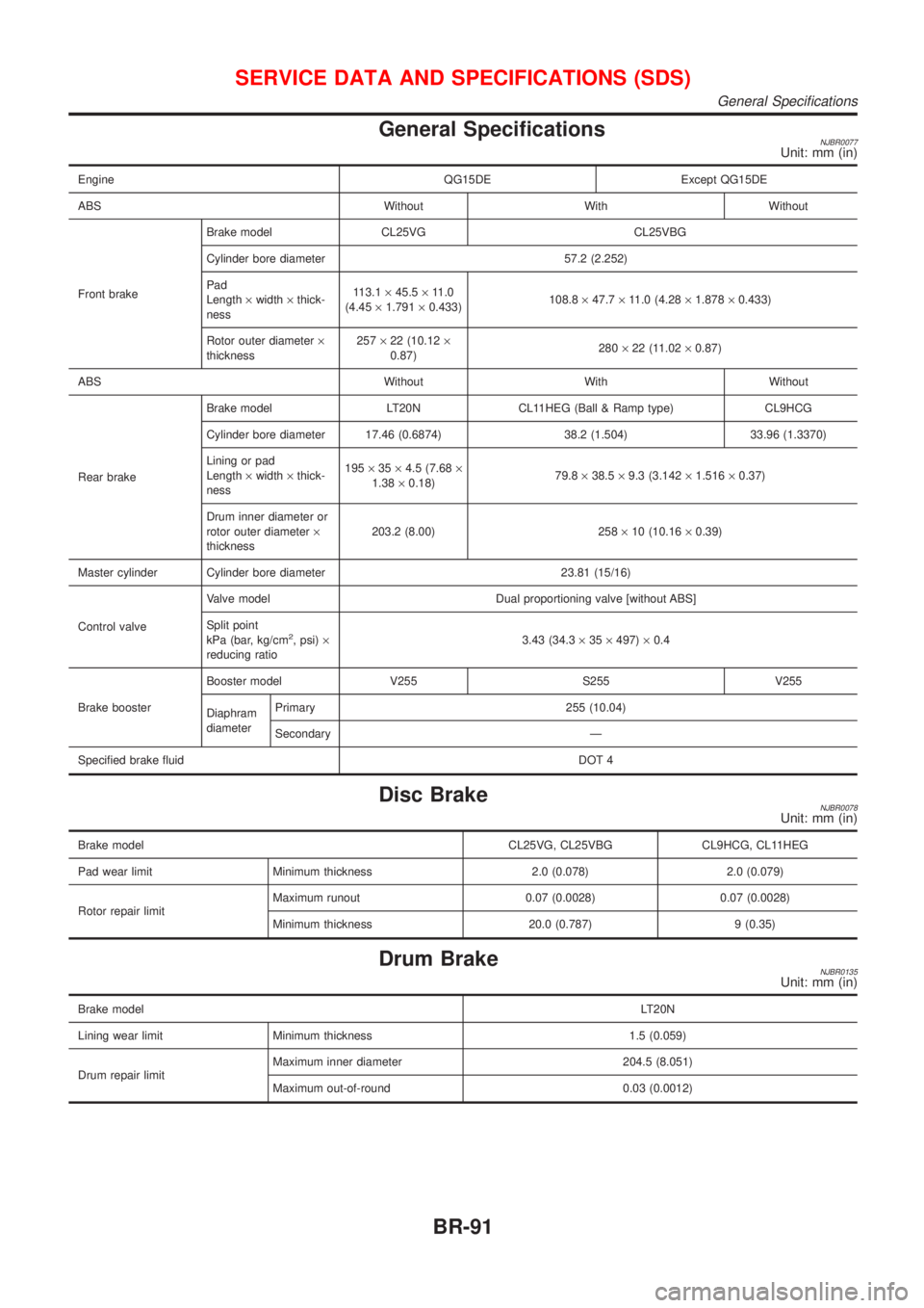
General SpecificationsNJBR0077Unit: mm (in)
Engine QG15DE Except QG15DE
ABS Without With Without
Front brakeBrake model CL25VG CL25VBG
Cylinder bore diameter 57.2 (2.252)
Pad
Length´width´thick-
ness113.1´45.5´11.0
(4.45´1.791´0.433)108.8´47.7´11.0 (4.28´1.878´0.433)
Rotor outer diameter´
thickness257´22 (10.12´
0.87)280´22 (11.02´0.87)
ABS Without With Without
Rear brakeBrake model LT20N CL11HEG (Ball & Ramp type) CL9HCG
Cylinder bore diameter 17.46 (0.6874) 38.2 (1.504) 33.96 (1.3370)
Lining or pad
Length´width´thick-
ness195´35´4.5 (7.68´
1.38´0.18)79.8´38.5´9.3 (3.142´1.516´0.37)
Drum inner diameter or
rotor outer diameter´
thickness203.2 (8.00) 258´10 (10.16´0.39)
Master cylinder Cylinder bore diameter 23.81 (15/16)
Control valveValve model Dual proportioning valve [without ABS]
Split point
kPa (bar, kg/cm
2, psi)´
reducing ratio3.43 (34.3´35´497)´0.4
Brake boosterBooster model V255 S255 V255
Diaphram
diameterPrimary 255 (10.04)
Secondary Ð
Specified brake fluidDOT 4
Disc BrakeNJBR0078Unit: mm (in)
Brake model CL25VG, CL25VBG CL9HCG, CL11HEG
Pad wear limit Minimum thickness 2.0 (0.078) 2.0 (0.079)
Rotor repair limitMaximum runout 0.07 (0.0028) 0.07 (0.0028)
Minimum thickness 20.0 (0.787) 9 (0.35)
Drum BrakeNJBR0135Unit: mm (in)
Brake modelLT20N
Lining wear limit Minimum thickness 1.5 (0.059)
Drum repair limitMaximum inner diameter 204.5 (8.051)
Maximum out-of-round 0.03 (0.0012)
SERVICE DATA AND SPECIFICATIONS (SDS)
General Specifications
BR-91
Page 2376 of 2493
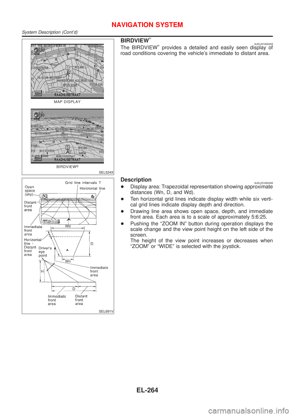
MAP DISPLAY
BIRDVIEW
R
SEL524X
BIRDVIEWTNJEL0516S0205The BIRDVIEWTprovides a detailed and easily seen display of
road conditions covering the vehicle's immediate to distant area.
SEL691V
DescriptionNJEL0516S0206+Display area: Trapezoidal representation showing approximate
distances (Wn, D, and Wd).
+Ten horizontal grid lines indicate display width while six verti-
cal grid lines indicate display depth and direction.
+Drawing line area shows open space, depth, and immediate
front area. Each area is to a scale of approximately 5:6:25.
+Pushing the ªZOOM INº button during operation displays the
scale change and the view point height on the left side of the
screen.
The height of the view point increases or decreases when
ªZOOMº or ªWIDEº is selected with the joystick.
NAVIGATION SYSTEM
System Description (Cont'd)
EL-264