Page 1076 of 2493

NJMT0090
SMT928D
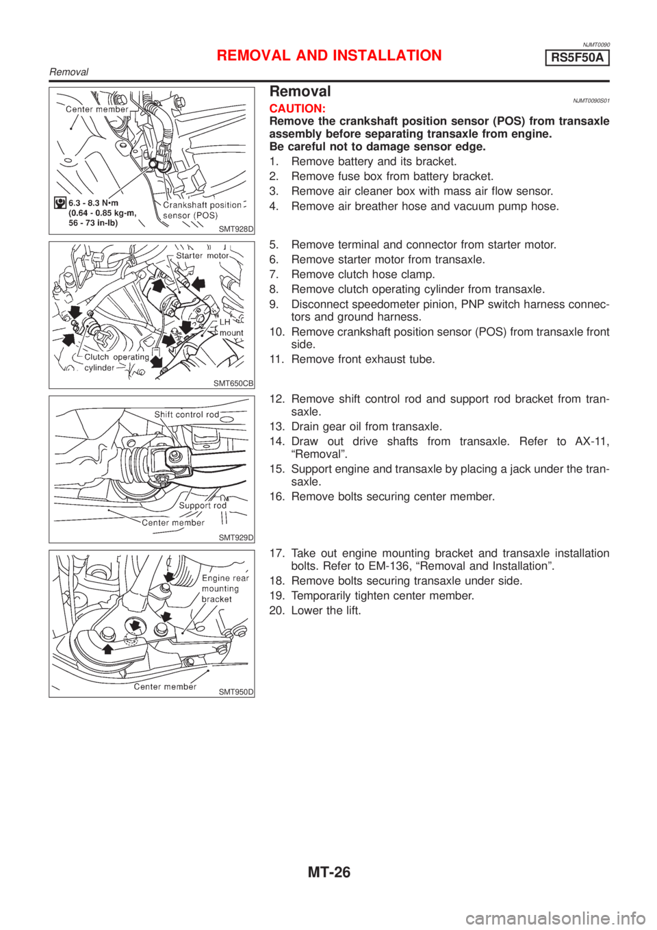
RemovalNJMT0090S01CAUTION:
Remove the crankshaft position sensor (POS) from transaxle
assembly before separating transaxle from engine.
Be careful not to damage sensor edge.
1. Remove battery and its bracket.
2. Remove fuse box from battery bracket.
3. Remove air cleaner box with mass air flow sensor.
4. Remove air breather hose and vacuum pump hose.
SMT650CB
5. Remove terminal and connector from starter motor.
6. Remove starter motor from transaxle.
7. Remove clutch hose clamp.
8. Remove clutch operating cylinder from transaxle.
9. Disconnect speedometer pinion, PNP switch harness connec-
tors and ground harness.
10. Remove crankshaft position sensor (POS) from transaxle front
side.
11. Remove front exhaust tube.
SMT929D
12. Remove shift control rod and support rod bracket from tran-
saxle.
13. Drain gear oil from transaxle.
14. Draw out drive shafts from transaxle. Refer to AX-11,
ªRemovalº.
15. Support engine and transaxle by placing a jack under the tran-
saxle.
16. Remove bolts securing center member.
SMT950D
17. Take out engine mounting bracket and transaxle installation
bolts. Refer to EM-136, ªRemoval and Installationº.
18. Remove bolts securing transaxle under side.
19. Temporarily tighten center member.
20. Lower the lift.
REMOVAL AND INSTALLATIONRS5F50A
Removal
MT-26
Page 1078 of 2493
SMT941D
InstallationNJMT0090S021. Put transaxle under the engine compartment.
2. Set chain block on transaxle and hang.
3. Lift up transaxle case so as not to hit against the side frame
and suspension member.
4. Assemble transaxle to engine.
+Tighten LH mount, rear side mount and center member bolts.
Refer to EM-136, ªRemoval and Installationº.
+Tighten clutch operating cylinder bolts. Refer to CL-15, ªInstal-
lationº.
+Tighten starter motor bolts. Refer to SC-19, ªRemoval and
Installationº.
+Install drive shafts. Refer to AX-12, ªInstallationº.
+Tighten all transaxle bolts and any part removed.
SMT932D
MODEL YD ENGINENJMT0090S0201
Bolt No. Tightening torque N´m (kg-m, ft-lb) ª!º mm (in)
140 - 49 (4.0 - 5.0, 29 - 36) 70 (2.76)
230.4 - 36.3 (3.1 - 3.7, 23 - 26) 60 (2.36)
330.4 - 36.3 (3.1 - 3.7, 23 - 26) 55 (2.17)
REMOVAL AND INSTALLATIONRS5F50A
Installation
MT-28
Page 1532 of 2493

SAT065K
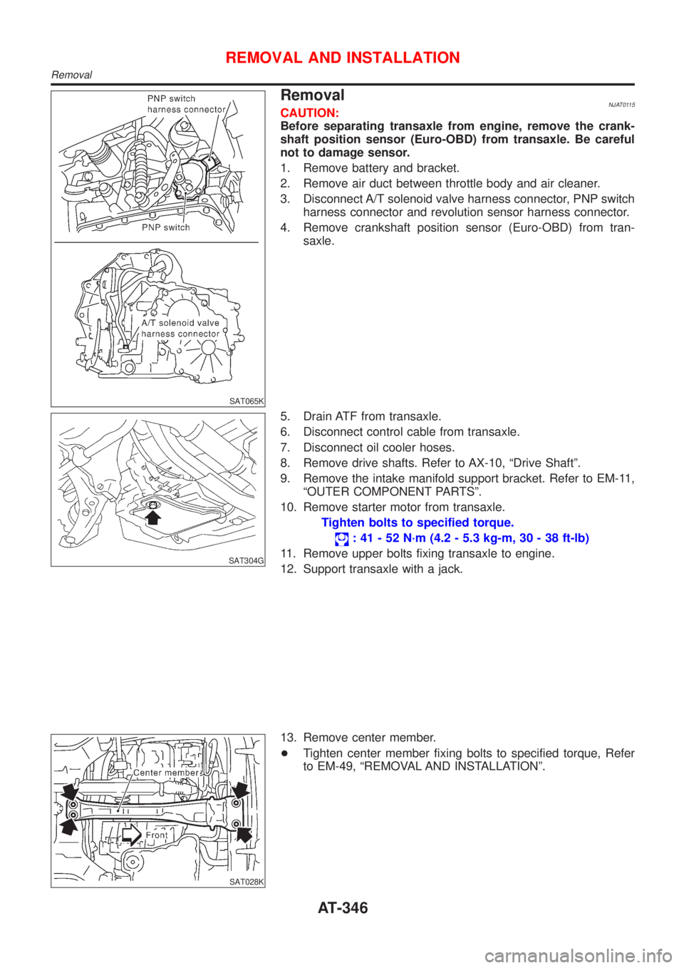
RemovalNJAT0115CAUTION:
Before separating transaxle from engine, remove the crank-
shaft position sensor (Euro-OBD) from transaxle. Be careful
not to damage sensor.
1. Remove battery and bracket.
2. Remove air duct between throttle body and air cleaner.
3. Disconnect A/T solenoid valve harness connector, PNP switch
harness connector and revolution sensor harness connector.
4. Remove crankshaft position sensor (Euro-OBD) from tran-
saxle.
SAT304G
5. Drain ATF from transaxle.
6. Disconnect control cable from transaxle.
7. Disconnect oil cooler hoses.
8. Remove drive shafts. Refer to AX-10, ªDrive Shaftº.
9. Remove the intake manifold support bracket. Refer to EM-11,
ªOUTER COMPONENT PARTSº.
10. Remove starter motor from transaxle.
Tighten bolts to specified torque.
: 41 - 52 N´m (4.2 - 5.3 kg-m, 30 - 38 ft-lb)
11. Remove upper bolts fixing transaxle to engine.
12. Support transaxle with a jack.
SAT028K
13. Remove center member.
+Tighten center member fixing bolts to specified torque, Refer
to EM-49, ªREMOVAL AND INSTALLATIONº.
REMOVAL AND INSTALLATION
Removal
AT-346
Page 2089 of 2493

System DescriptionNJSC0004M/T MODELSNJSC0004S01Power is supplied at all times
+through 40A fusible link (letterB, located in the fuse and fusible link box)
+to ignition switch terminal 1.
With the ignition switch in START position, power is supplied
+from ignition switch terminal 5
+to starter motor harness connector terminal 1.
The starter motor plunger closes and provides a closed circuit between the battery and starter motor. The
starter motor is grounded to the engine block. With power and ground supplied, cranking occurs and the engine
starts.
A/T MODELSNJSC0004S02Power is supplied at all times
+through 40A fusible link (letterB, located in the fuse and fusible link box)
+to ignition switch terminal 1.
With the ignition switch in the START position, power is supplied
+from ignition switch terminal 5
+to park/neutral position relay terminal 5.
With the ignition switch ON or START position, power is supplied
+through 10A fuse [No. 20, located in the fuse block (J/B)]
+to park/neutral position (PNP) relay terminal 1.
With the selector lever in the P or N position, ground is supplied
+to park/neutral position relay terminal 2 through the park/neutral position switch
+from body grounds, F9 and F10.
Then park/neutral position relay is energized and power is supplied
+from park/neutral position relay terminal 3
+to starter motor harness connector terminal 1.
The starter motor plunger closes and provides a closed circuit between the battery and starter motor. The
starter motor is grounded to the engine block. With power and ground supplied, cranking occurs and the engine
starts.
STARTING SYSTEM
System Description
SC-13
Page 2095 of 2493

SEL909TA
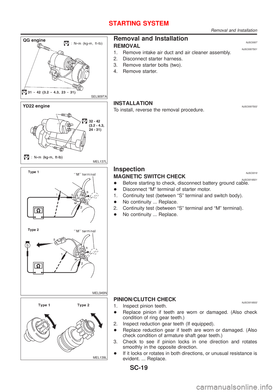
Removal and InstallationNJSC0007REMOVALNJSC0007S011. Remove intake air duct and air cleaner assembly.
2. Disconnect starter harness.
3. Remove starter bolts (two).
4. Remove starter.
MEL137L
INSTALLATIONNJSC0007S02To install, reverse the removal procedure.
MEL949N
InspectionNJSC0019MAGNETIC SWITCH CHECKNJSC0019S01+Before starting to check, disconnect battery ground cable.
+Disconnect ªMº terminal of starter motor.
1. Continuity test (between ªSº terminal and switch body).
+No continuity ... Replace.
2. Continuity test (between ªSº terminal and ªMº terminal).
+No continuity ... Replace.
MEL139L
PINION/CLUTCH CHECKNJSC0019S021. Inspect pinion teeth.
+Replace pinion if teeth are worn or damaged. (Also check
condition of ring gear teeth.)
2. Inspect reduction gear teeth (If equipped).
+Replace reduction gear if teeth are worn or damaged. (Also
check condition of armature shaft gear teeth.)
3. Check to see if pinion locks in one direction and rotates
smoothly in the opposite direction.
+If it locks or rotates in both directions, or unusual resistance is
evident. ... Replace.
STARTING SYSTEM
Removal and Installation
SC-19