Page 109 of 2493
SEM909F
ReplacementNJEM0015VALVE OIL SEALNJEM0015S011. Remove rocker cover.
2. Remove camshaft.
3. Remove valve spring. Refer to EM-36.
4. Remove valve oil seal with Tool.
Piston concerned should be set at TDC to prevent valve from
falling.
SEM910F
5. Apply new engine oil to new valve oil seal and install it with
Tool.
SEM911F
FRONT OIL SEALNJEM0015S021. Remove the following parts:
+Engine under cover
+RH engine side cover
+Alternator and power steering drive belts
+Crankshaft pulley
2. Remove front oil seal from front cover.
+Be careful not to scratch front cover.
SEM715A
SEM912F
3. Apply new engine oil to new oil seal and install it using a suit-
able tool.
+Install new oil seal in the direction shown.
OIL SEALQG
Replacement
EM-31
Page 128 of 2493

WARNING:
+Position vehicle on a flat and solid surface.
+Place chocks at front and back of rear wheels.
+Do not remove engine until exhaust system has com-
pletely cooled off, otherwise, you may burn yourself
and/or fire may break out in fuel line.
+Before disconnecting fuel hose, release pressure.
Refer to EC-38, ªFuel Pressure Releaseº.
+Be sure to lift engine and transaxle in a safe manner.
+For engines not equipped with engine slingers, attach
proper slingers and bolts described in PARTS CATALOG.
CAUTION:
+When lifting engine, be sure to clear surrounding parts.
Use special care near accelerator wire casing, brake lines
and brake master cylinder.
+When lifting the engine, always use engine slingers in a
safe manner.
+When removing drive shaft, be careful not to damage
grease seal of transaxle.
+Before separating engine and transaxle, remove crank-
shaft position sensor (POS) from the cylinder block
assembly.
+Always be extra careful not to damage edge of crankshaft
position sensor (POS), or signal plate teeth.
Engine cannot be removed separately from transaxle. Remove
engine with transaxle as an assembly.
REMOVALNJEM0022S011. Drain coolant from radiator and cylinder block. Refer to LC-17,
ªChanging Engine Coolantº.
2. Remove coolant reservoir tank and bracket.
3. Drain engine oil.
4. Remove battery and battery tray.
5. Remove air cleaner and air duct.
6. Remove drive belts.
7. Remove alternator and air conditioner compressor from
engine.
8. Remove power steering oil pump from engine and position
aside.
Power steering oil pump does not need to be disconnected
from power steering tubes.
ENGINE ASSEMBLYQG
Removal and Installation (Cont'd)
EM-50
Page 143 of 2493
Applied engineUsed belt deflection
Deflection of new belt
LimitDeflection after adjust-
ment
Power steering oil pumpQG15DE 8.5 (0.335)5.2 - 5.8
(0.205 - 0.228)4.6 - 5.2
(0.181 - 0.205)
QG18DE 7.1 (0.280)4.4 - 4.9
(0.173 - 0.193)3.9 - 4.4
(0.154 - 0.173)
Applied pushing force 98 N (10 kg, 22 lb)
Spark PlugNJEM0046
NGK Champion
TypeStandard BKR5E-11 RC10YC4
Hot BKR4E-11 Ð
Cold BKR6E-11 Ð
Plug gap mm (in)1.0 - 1.1 (0.039 - 0.043)
Cylinder HeadNJEM0030Unit: mm (in)
Standard Limit
Head surface flatness Less than 0.03 (0.0012) 0.1 (0.004)
Height 117.8 - 118.0 (4.638 - 4.646) Ð
SERVICE DATA AND SPECIFICATIONS (SDS)QG
Belt Deflection (Cont'd)
EM-65
Page 172 of 2493

JEM121G
3. Remove front chain case.
+Move power steering fluid reservoir tank from the bracket.
+Loosen fixing bolts in the reverse order of that shown in the
figure and remove them.
+Remove No. 6, 10, and 11 bolts with the rubber washer as
space is limited for pulling them out.
SEM514G
CAUTION:
+While front chain case is removed, cover openings to pre-
vent entry of foreign material into engine.
+Do not remove two mass dampers on the back of cover.
SEM515G
4. Set the No. 1 piston to TDC on its compression stroke.
+Turn crankshaft pulley clockwise so that the alignment mark
(punched mark) on each camshaft sprocket is positioned as
shown in the figure.
+No position indicator is provided on the crankshaft pulley.
+When installing, color coded links on the secondary tim-
ing chain can be used as alignment marks. Marking may
not be necessary for removal; however, make alignment
marks as required because the alignment mark on fuel
injection pump sprocket may not be easy to see.
JEM124G
5. Remove chain tensioner.
a. Push the plunger of chain tensioner and keep it pressed with
a push pin.
JEM125G
b. Using a hexagon-head wrench (face to face: 5 mm, SST),
remove bolts to remove chain tensioner.
TIMING CHAINYD
Secondary Timing Chain (Cont'd)
EM-94
Page 178 of 2493
JEM134G
9. Remove chain tensioner.
+When removing chain tensioner, push the sleeve of chain ten-
sioner and keep it pressed with a push pin, etc.
10. Remove timing chain slack guide.
JEM135G
11. Hold fuel injection pump sprocket and remove bolt.
a. Insert positioning stopper pin (SST) into the hole 6 mm (0.24
in) in the diameter on the fuel injection pump sprocket.
b. Using a TORX wrench (SST), turn pump shaft little by little to
adjust the position of fuel injection pump sprocket so that the
holes align.
c. Push positioning stopper pin (SST) through pump sprocket to
fuel injection pump body to hold pump sprocket, and remove
bolt.
JEM136G
12. Remove primary timing chain with fuel injection pump sprocket
and crankshaft sprocket.
JEM137G
13. Remove chain guide and tension guides.
14. Remove fuel injection pump.
15. Remove power steering pump.
TIMING CHAINYD
Primary Timing Chain (Cont'd)
EM-100
Page 181 of 2493

JEM137G
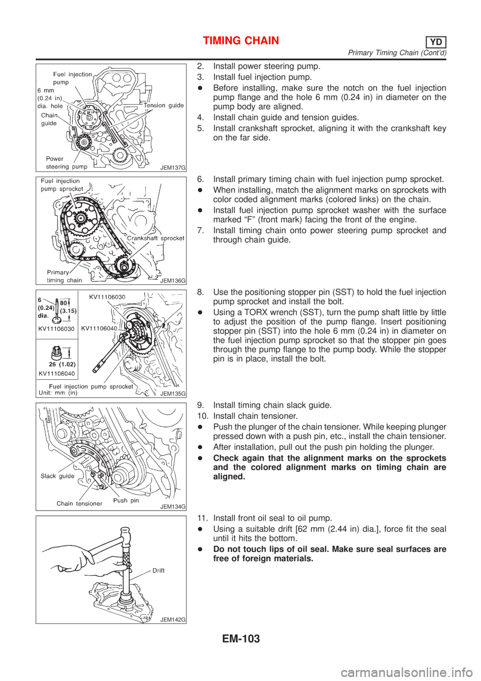
2. Install power steering pump.
3. Install fuel injection pump.
+Before installing, make sure the notch on the fuel injection
pump flange and the hole 6 mm (0.24 in) in diameter on the
pump body are aligned.
4. Install chain guide and tension guides.
5. Install crankshaft sprocket, aligning it with the crankshaft key
on the far side.
JEM136G
6. Install primary timing chain with fuel injection pump sprocket.
+When installing, match the alignment marks on sprockets with
color coded alignment marks (colored links) on the chain.
+Install fuel injection pump sprocket washer with the surface
marked ªFº (front mark) facing the front of the engine.
7. Install timing chain onto power steering pump sprocket and
through chain guide.
JEM135G
8. Use the positioning stopper pin (SST) to hold the fuel injection
pump sprocket and install the bolt.
+Using a TORX wrench (SST), turn the pump shaft little by little
to adjust the position of the pump flange. Insert positioning
stopper pin (SST) into the hole 6 mm (0.24 in) in diameter on
the fuel injection pump sprocket so that the stopper pin goes
through the pump flange to the pump body. While the stopper
pin is in place, install the bolt.
JEM134G
9. Install timing chain slack guide.
10. Install chain tensioner.
+Push the plunger of the chain tensioner. While keeping plunger
pressed down with a push pin, etc., install the chain tensioner.
+After installation, pull out the push pin holding the plunger.
+Check again that the alignment marks on the sprockets
and the colored alignment marks on timing chain are
aligned.
JEM142G
11. Install front oil seal to oil pump.
+Using a suitable drift [62 mm (2.44 in) dia.], force fit the seal
until it hits the bottom.
+Do not touch lips of oil seal. Make sure seal surfaces are
free of foreign materials.
TIMING CHAINYD
Primary Timing Chain (Cont'd)
EM-103
Page 182 of 2493

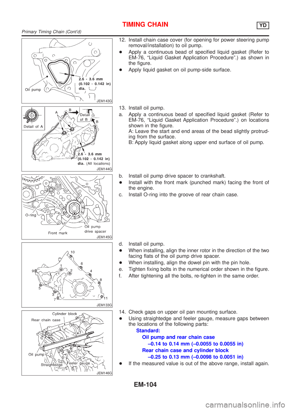
JEM143G
12. Install chain case cover (for opening for power steering pump
removal/installation) to oil pump.
+Apply a continuous bead of specified liquid gasket (Refer to
EM-76, ªLiquid Gasket Application Procedureº.) as shown in
the figure.
+Apply liquid gasket on oil pump-side surface.
JEM144G
13. Install oil pump.
a. Apply a continuous bead of specified liquid gasket (Refer to
EM-76, ªLiquid Gasket Application Procedureº.) on locations
shown in the figure.
A: Leave the start and end areas of the bead slightly protrud-
ing from the surface.
B: Apply liquid gasket along upper end surface of oil pump.
JEM145G
b. Install oil pump drive spacer to crankshaft.
+Install with the front mark (punched mark) facing the front of
the engine.
c. Install O-ring into the groove of rear chain case.
JEM133G
d. Install oil pump.
+When installing, align the inner rotor in the direction of the two
facing flats of the oil pump drive spacer.
+When installing, align the dowel pin with the pin hole.
e. Tighten fixing bolts in the numerical order shown in the figure.
f. After tightening all the bolts, re-tighten in the same order.
JEM146G
14. Check gaps on upper oil pan mounting surface.
+Using straightedge and feeler gauge, measure gaps between
the locations of the following parts:
Standard:
Oil pump and rear chain case
±0.14 to 0.14 mm (±0.0055 to 0.0055 in)
Rear chain case and cylinder block
±0.25 to 0.13 mm (±0.0098 to 0.0051 in)
+If the measured value is out of the above range, install again.
TIMING CHAINYD
Primary Timing Chain (Cont'd)
EM-104
Page 215 of 2493

crankshaft position sensor (TDC sensor) from the assem-
bly.
+Always pay extra attention not to damage edge of crank-
shaft position sensor (TDC sensor) or ring gear teeth.
REMOVALNJEM0069S011. Remove engine undercover, and hood for hoisting.
2. Drain coolant from both cylinder block and radiator. Refer to
LC-43, ªChanging Engine Coolantº.
3. Remove the following parts:
+Battery
+RH and LH front wheels
+RH and LH splash covers (combined with undercover)
+Auxiliary belts
+Alternator
+Alternator brackets
+Radiator and cooling fan
+Engine cover
+Air ducts and air cleaner case
LH side of engine room:
4. Disconnect all harnesses and grounds that are connected to
components on vehicle.
5. Disconnect vacuum hose on vacuum pump side.
6. Disconnect fuel feed and fuel return hoses on engine side.
+Immediately put blind plugs into the openings to prevent
fuel from flowing out.
7. Disconnect heater hose. Plug opening of hose to prevent cool-
ant from flowing out.
RH side of engine room:
8. Remove air conditioner compressor from brackets and move
it toward vehicle side. Secure compressor on vehicle side with
rope.
Vehicle underside:
9. Remove exhaust front tube.
10. Disconnect two hoses from power steering pump and plug to
stop fluid.
11. Remove M/T control rod and support rod.
12. Remove ABS wheel sensor, and temporarily hang brake cali-
per with rope on vehicle side.
13. Remove RH and LH drive shafts.
YEM024
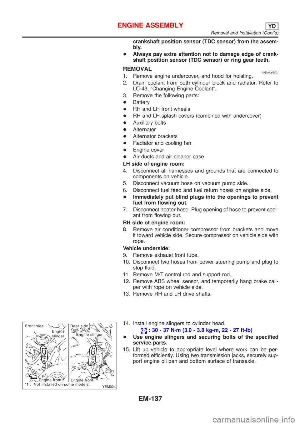
14. Install engine slingers to cylinder head.
: 30 - 37 N´m (3.0 - 3.8 kg-m, 22 - 27 ft-lb)
+Use engine slingers and securing bolts of the specified
service parts.
15. Lift up vehicle to appropriate level where work can be per-
formed efficiently. Using two transmission jacks, securely sup-
port engine oil pan and bottom surface of transaxle.
ENGINE ASSEMBLYYD
Removal and Installation (Cont'd)
EM-137