2001 NISSAN ALMERA N16 power steering
[x] Cancel search: power steeringPage 810 of 2493

JEF351Y
2. Disconnect the fuel hoses from the fuel injection pump.
3. Disconnect the harness connector from the fuel injection
pump.
+Disconnect the connector by pulling the connector stopper
fully.
+When the stopper is fully pulled, the connector will be discon-
nected together. For installation, push the connector half way
first, then press the stopper until it locks, so that the connec-
tor is connected together.
4. Remove the fuel injection pump rear bracket.
JEF352Y
5. Remove the front chain case.
+Move the power steering fluid reservoir tank from the bracket.
+Loosen and remove the mounting bolts in the reverse order of
the numbers shown in the figure.
+As for bolts 6, 10, and 11, remove with rubber washer because
there is not enough space for removing only the bolts.
CAUTION:
To prevent foreign objects from getting in the engine, cover
the opening during the removal of the front chain case.
JEF353Y
6. Adjust the No. 1 cylinder to the top dead center position.
+Turn the crankshaft pulley clockwise, then align the alignment
mark (punched mark) of the camshaft sprocket to the position
shown in the figure.
+There is no indicator on the crankshaft pulley.
+It is not necessary to mark the secondary timing chain for
removal because it can be matched by the link color for instal-
lation. However, the alignment mark on the fuel injection pump
sprocket is difficult to see; mark it if necessary.
JEF354Y
7. Remove the chain tensioner.
a. Push the plunger of the chain tensioner, then fix it with a tool
such as a push pin.
JEF355Y
b. Using the hexagon wrench (face to face: 5 mm) (SST), remove
the mounting bolts, then remove the chain tensioner.
+A multi-purpose tool may also be used.
BASIC SERVICE PROCEDUREYD
Electronic Control Fuel Injection Pump (Cont'd)
EC-514
Page 1680 of 2493
AFA050
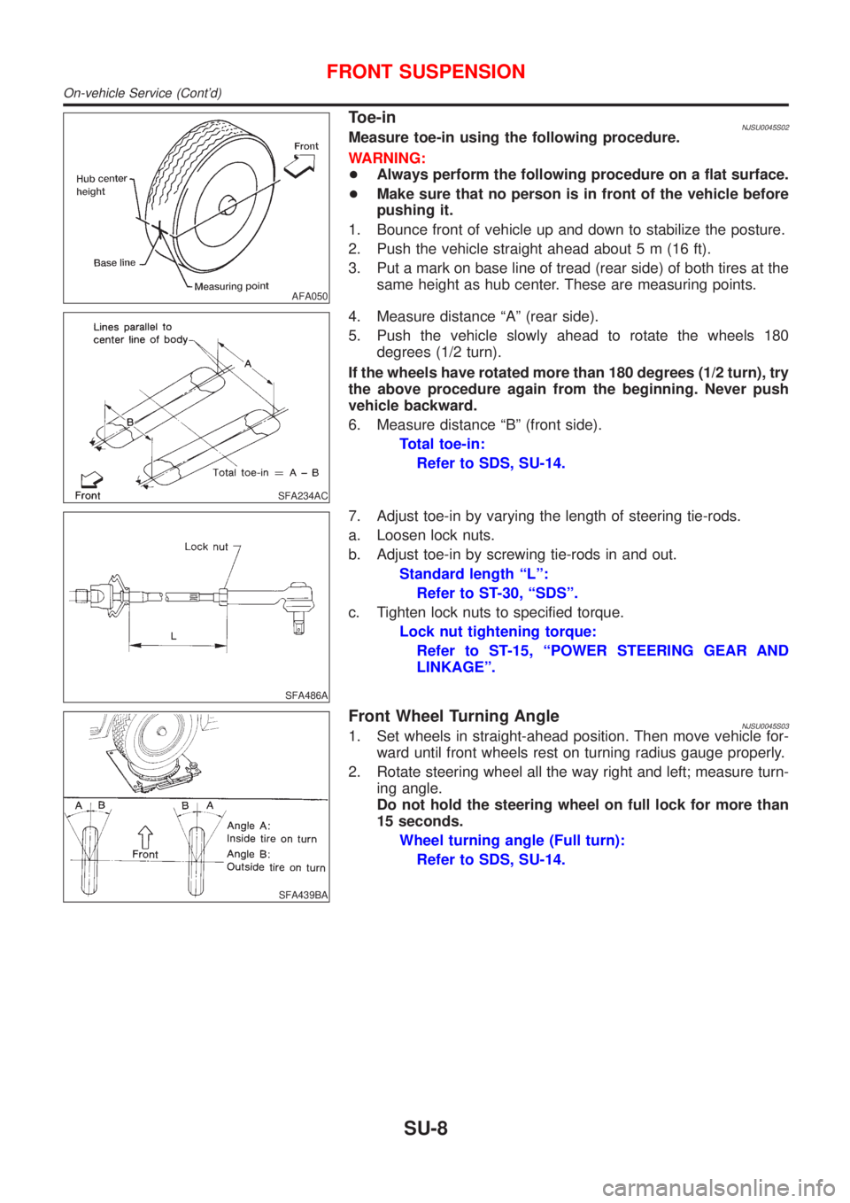
Toe-inNJSU0045S02Measure toe-in using the following procedure.
WARNING:
+Always perform the following procedure on a flat surface.
+Make sure that no person is in front of the vehicle before
pushing it.
1. Bounce front of vehicle up and down to stabilize the posture.
2. Push the vehicle straight ahead about 5 m (16 ft).
3. Put a mark on base line of tread (rear side) of both tires at the
same height as hub center. These are measuring points.
SFA234AC
4. Measure distance ªAº (rear side).
5. Push the vehicle slowly ahead to rotate the wheels 180
degrees (1/2 turn).
If the wheels have rotated more than 180 degrees (1/2 turn), try
the above procedure again from the beginning. Never push
vehicle backward.
6. Measure distance ªBº (front side).
Total toe-in:
Refer to SDS, SU-14.
SFA486A
7. Adjust toe-in by varying the length of steering tie-rods.
a. Loosen lock nuts.
b. Adjust toe-in by screwing tie-rods in and out.
Standard length ªLº:
Refer to ST-30, ªSDSº.
c. Tighten lock nuts to specified torque.
Lock nut tightening torque:
Refer to ST-15, ªPOWER STEERING GEAR AND
LINKAGEº.
SFA439BA
Front Wheel Turning AngleNJSU0045S031. Set wheels in straight-ahead position. Then move vehicle for-
ward until front wheels rest on turning radius gauge properly.
2. Rotate steering wheel all the way right and left; measure turn-
ing angle.
Do not hold the steering wheel on full lock for more than
15 seconds.
Wheel turning angle (Full turn):
Refer to SDS, SU-14.
FRONT SUSPENSION
On-vehicle Service (Cont'd)
SU-8
Page 1686 of 2493
Service Data and Specifications (SDS)
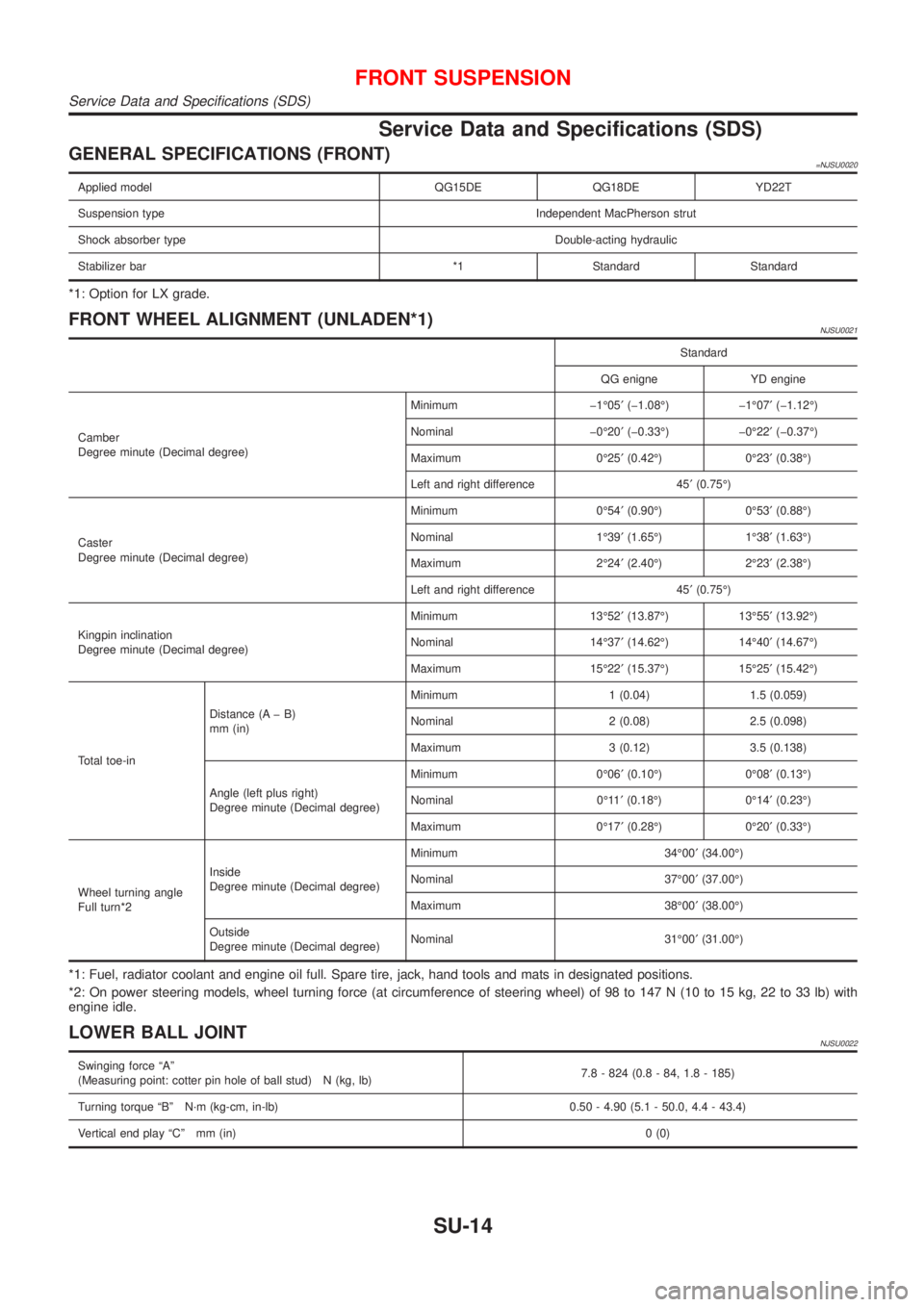
GENERAL SPECIFICATIONS (FRONT)=NJSU0020
Applied model QG15DE QG18DE YD22T
Suspension type Independent MacPherson strut
Shock absorber type Double-acting hydraulic
Stabilizer bar *1 Standard Standard
*1: Option for LX grade.
FRONT WHEEL ALIGNMENT (UNLADEN*1)NJSU0021
Standard
QG enigne YD engine
Camber
Degree minute (Decimal degree)Minimum þ1É05¢(þ1.08É) þ1É07¢(þ1.12É)
Nominal þ0É20¢(þ0.33É) þ0É22¢(þ0.37É)
Maximum 0É25¢(0.42É) 0É23¢(0.38É)
Left and right difference 45¢(0.75É)
Caster
Degree minute (Decimal degree)Minimum 0É54¢(0.90É) 0É53¢(0.88É)
Nominal 1É39¢(1.65É) 1É38¢(1.63É)
Maximum 2É24¢(2.40É) 2É23¢(2.38É)
Left and right difference 45¢(0.75É)
Kingpin inclination
Degree minute (Decimal degree)Minimum 13É52¢(13.87É) 13É55¢(13.92É)
Nominal 14É37¢(14.62É) 14É40¢(14.67É)
Maximum 15É22¢(15.37É) 15É25¢(15.42É)
Total toe-inDistance (A þ B)
mm (in)Minimum 1 (0.04) 1.5 (0.059)
Nominal 2 (0.08) 2.5 (0.098)
Maximum 3 (0.12) 3.5 (0.138)
Angle (left plus right)
Degree minute (Decimal degree)Minimum 0É06¢(0.10É) 0É08¢(0.13É)
Nominal 0É11¢(0.18É) 0É14¢(0.23É)
Maximum 0É17¢(0.28É) 0É20¢(0.33É)
Wheel turning angle
Full turn*2Inside
Degree minute (Decimal degree)Minimum 34É00¢(34.00É)
Nominal 37É00¢(37.00É)
Maximum 38É00¢(38.00É)
Outside
Degree minute (Decimal degree)Nominal 31É00¢(31.00É)
*1: Fuel, radiator coolant and engine oil full. Spare tire, jack, hand tools and mats in designated positions.
*2: On power steering models, wheel turning force (at circumference of steering wheel) of 98 to 147 N (10 to 15 kg, 22 to 33 lb) with
engine idle.
LOWER BALL JOINTNJSU0022
Swinging force ªAº
(Measuring point: cotter pin hole of ball stud) N (kg, lb)7.8 - 824 (0.8 - 84, 1.8 - 185)
Turning torque ªBº N´m (kg-cm, in-lb) 0.50 - 4.90 (5.1 - 50.0, 4.4 - 43.4)
Vertical end play ªCº mm (in)0 (0)
FRONT SUSPENSION
Service Data and Specifications (SDS)
SU-14
Page 1791 of 2493
STEERING SYSTEM
SECTION
ST
CONTENTS
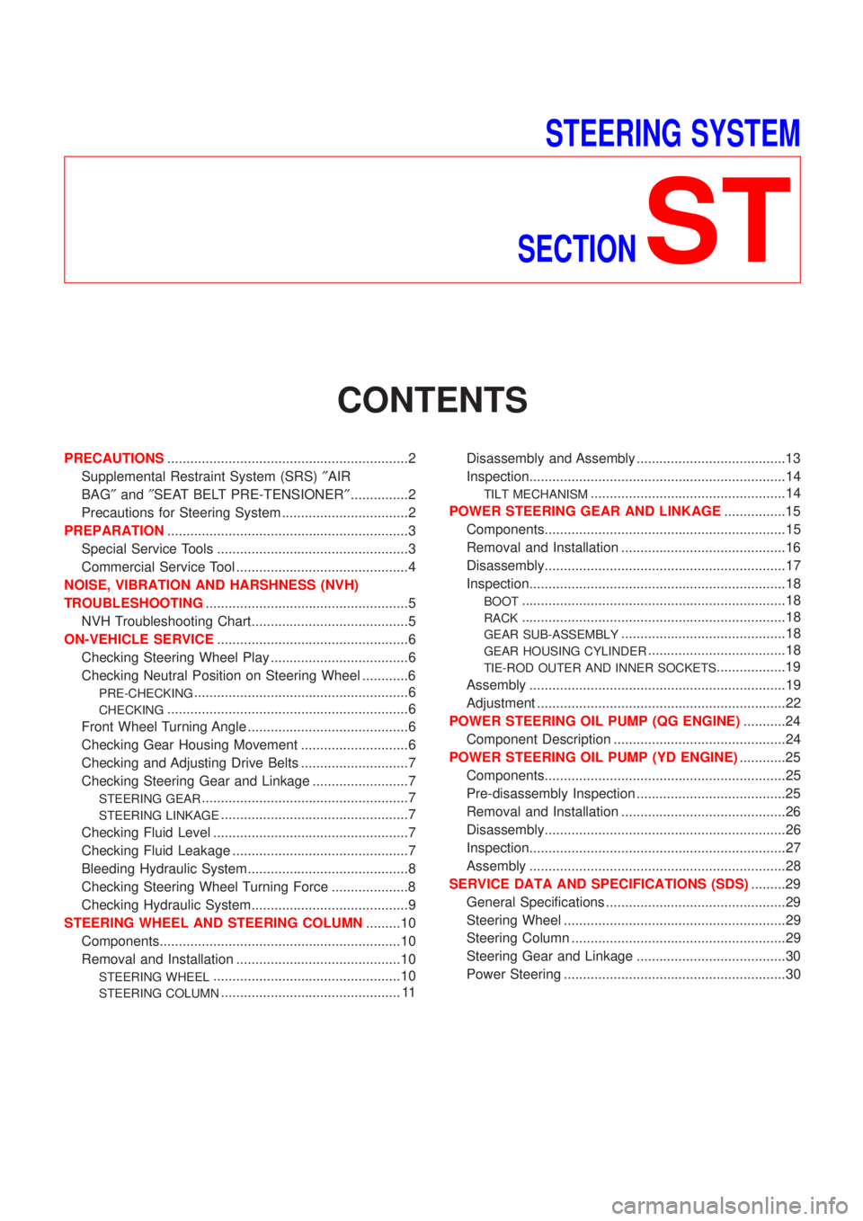
PRECAUTIONS...............................................................2
Supplemental Restraint System (SRS)²AIR
BAG²and²SEAT BELT PRE-TENSIONER²...............2
Precautions for Steering System .................................2
PREPARATION...............................................................3
Special Service Tools ..................................................3
Commercial Service Tool .............................................4
NOISE, VIBRATION AND HARSHNESS (NVH)
TROUBLESHOOTING.....................................................5
NVH Troubleshooting Chart.........................................5
ON-VEHICLE SERVICE..................................................6
Checking Steering Wheel Play ....................................6
Checking Neutral Position on Steering Wheel ............6
PRE-CHECKING........................................................6
CHECKING...............................................................6
Front Wheel Turning Angle ..........................................6
Checking Gear Housing Movement ............................6
Checking and Adjusting Drive Belts ............................7
Checking Steering Gear and Linkage .........................7
STEERING GEAR......................................................7
STEERING LINKAGE.................................................7
Checking Fluid Level ...................................................7
Checking Fluid Leakage ..............................................7
Bleeding Hydraulic System..........................................8
Checking Steering Wheel Turning Force ....................8
Checking Hydraulic System.........................................9
STEERING WHEEL AND STEERING COLUMN.........10
Components...............................................................10
Removal and Installation ...........................................10
STEERING WHEEL.................................................10
STEERING COLUMN............................................... 11Disassembly and Assembly .......................................13
Inspection...................................................................14
TILT MECHANISM...................................................14
POWER STEERING GEAR AND LINKAGE................15
Components...............................................................15
Removal and Installation ...........................................16
Disassembly...............................................................17
Inspection...................................................................18
BOOT.....................................................................18
RACK.....................................................................18
GEAR SUB-ASSEMBLY...........................................18
GEAR HOUSING CYLINDER....................................18
TIE-ROD OUTER AND INNER SOCKETS..................19
Assembly ...................................................................19
Adjustment .................................................................22
POWER STEERING OIL PUMP (QG ENGINE)...........24
Component Description .............................................24
POWER STEERING OIL PUMP (YD ENGINE)............25
Components...............................................................25
Pre-disassembly Inspection .......................................25
Removal and Installation ...........................................26
Disassembly...............................................................26
Inspection...................................................................27
Assembly ...................................................................28
SERVICE DATA AND SPECIFICATIONS (SDS).........29
General Specifications ...............................................29
Steering Wheel ..........................................................29
Steering Column ........................................................29
Steering Gear and Linkage .......................................30
Power Steering ..........................................................30
Page 1792 of 2493
Supplemental Restraint System (SRS) ªAIR
BAGº and ªSEAT BELT PRE-TENSIONERº
NJST0044The Supplemental Restraint System such as ªAIR BAGº and ªSEAT BELT PRE-TENSIONERº used along with
a seat belt, helps to reduce the risk or severity of injury to the driver and front passenger for certain types of
collision. The SRS system composition which is available to NISSAN MODEL N16 is as follows (The compo-
sition varies according to the destination and optional equipment.):
+For a frontal collision
The Supplemental Restraint System consists of driver air bag module (located in the center of the steer-
ing wheel), front passenger air bag module (located on the instrument panel on passenger side), front seat
belt pre-tensioners, a diagnosis sensor unit, warning lamp, wiring harness and spiral cable.
+For a side collision
The Supplemental Restraint System consists of front side air bag module (located in the outer side of front
seat), side air bag (satellite) sensor, diagnosis sensor unit (one of components of air bags for a frontal
collision), wiring harness, warning lamp (one of components of air bags for a frontal collision).
Information necessary to service the system safely is included in theRS sectionof this Service Manual.
WARNING:
+To avoid rendering the SRS inoperative, which could increase the risk of personal injury or death
in the event of a collision which would result in air bag inflation, all maintenance should be per-
formed by an authorized NISSAN dealer.
+Improper maintenance, including incorrect removal and installation of the SRS, can lead to per-
sonal injury caused by unintentional activation of the system. For removal of Spiral Cable and Air
Bag Module, see the RS section.
+Do not use electrical test equipment on any circuit related to the SRS unless instructed to in this
Service Manual. SRS wiring harnesses (except ªSEAT BELT PRE-TENSIONERº connector) can be
identified by yellow harness connector.
Precautions for Steering SystemNJST0003+Before disassembly, thoroughly clean the outside of the unit.
+Disassembly should be done in a clean work area. It is important to prevent the internal parts from
becoming contaminated by dirt or other foreign matter.
+Place disassembled parts in order, on a parts rack, for easier and proper assembly.
+Use nylon cloths or paper towels to clean the parts; common shop rags can leave lint that might
interfere with their operation.
+Before inspection or reassembly, carefully clean all parts with a general purpose, non-flammable
solvent.
+Before assembly, apply a coat of recommended power steering fluid* to hydraulic parts. Vaseline
may be applied to O-rings and seals. Do not use any grease.
+Replace all gaskets, seals and O-rings. Avoid damaging O-rings, seals and gaskets during instal-
lation. Perform functional tests whenever designated.
*: DEXRON
TMIII or equivalent. Refer to MA-20, ªFluids and Lubricantsº.
PRECAUTIONS
Supplemental Restraint System (SRS) ªAIR BAGº and ªSEAT BELT PRE-TENSIONERº
ST-2
Page 1794 of 2493
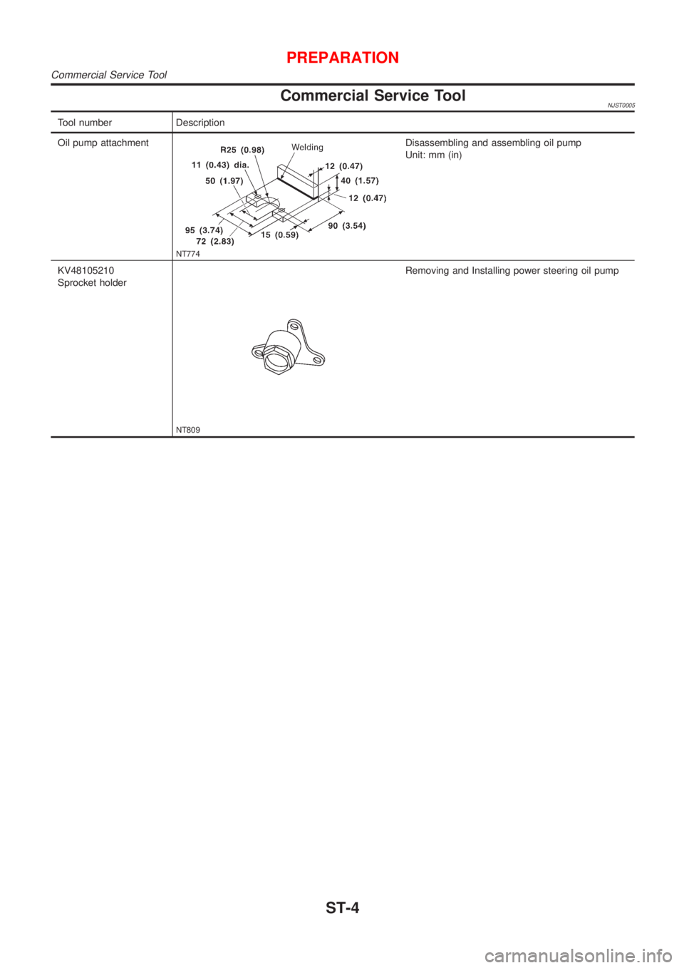
Commercial Service ToolNJST0005
Tool number Description
Oil pump attachment
NT774
Disassembling and assembling oil pump
Unit: mm (in)
KV48105210
Sprocket holder
NT809
Removing and Installing power steering oil pump
PREPARATION
Commercial Service Tool
ST-4
Page 1797 of 2493
Checking and Adjusting Drive BeltsNJST0011Refer to EM-15, ªChecking Drive Beltsº.
SMA851B
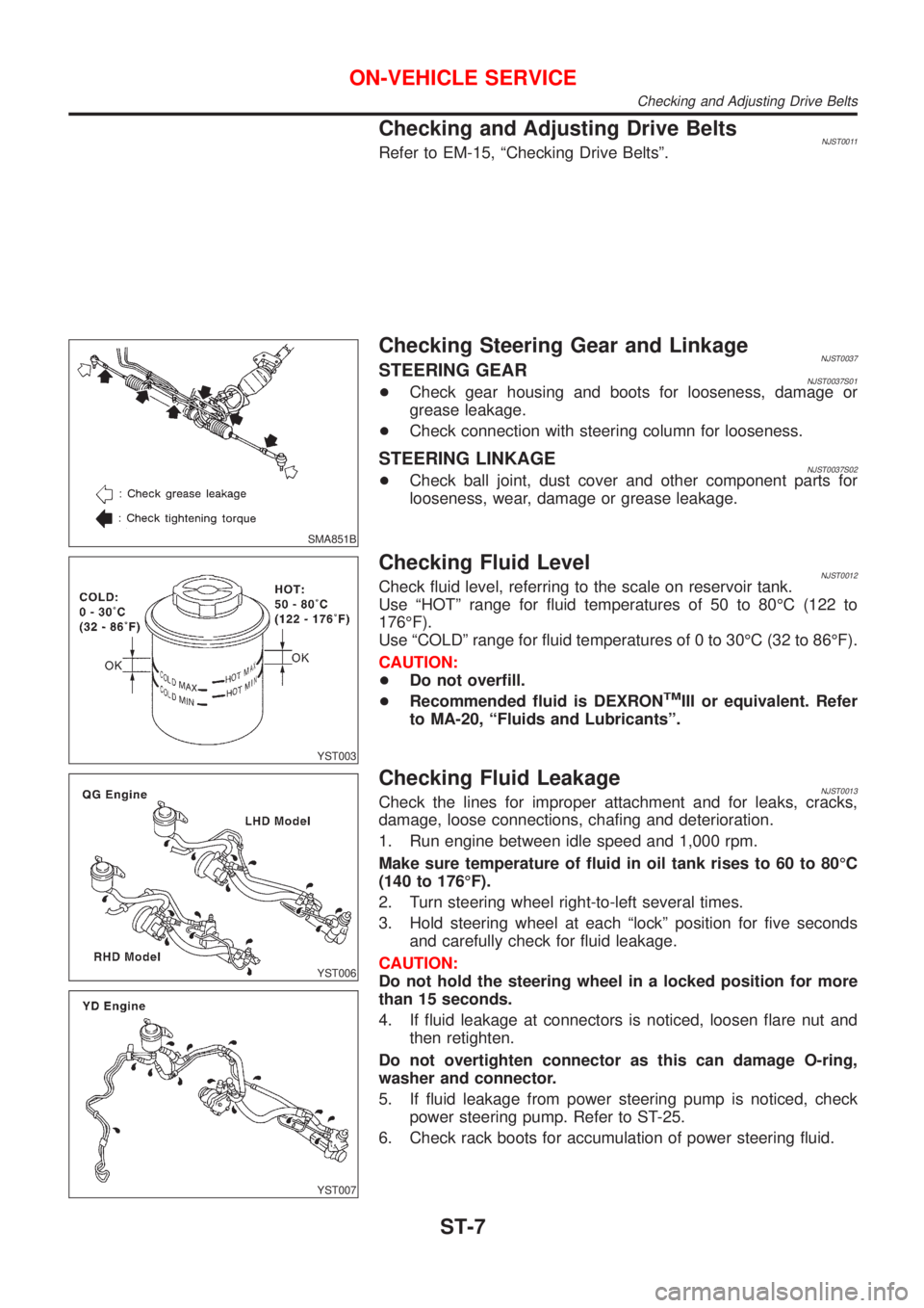
Checking Steering Gear and LinkageNJST0037STEERING GEARNJST0037S01+Check gear housing and boots for looseness, damage or
grease leakage.
+Check connection with steering column for looseness.
STEERING LINKAGENJST0037S02+Check ball joint, dust cover and other component parts for
looseness, wear, damage or grease leakage.
YST003
Checking Fluid LevelNJST0012Check fluid level, referring to the scale on reservoir tank.
Use ªHOTº range for fluid temperatures of 50 to 80ÉC (122 to
176ÉF).
Use ªCOLDº range for fluid temperatures of 0 to 30ÉC (32 to 86ÉF).
CAUTION:
+Do not overfill.
+Recommended fluid is DEXRON
TMIII or equivalent. Refer
to MA-20, ªFluids and Lubricantsº.
YST006
YST007
Checking Fluid LeakageNJST0013Check the lines for improper attachment and for leaks, cracks,
damage, loose connections, chafing and deterioration.
1. Run engine between idle speed and 1,000 rpm.
Make sure temperature of fluid in oil tank rises to 60 to 80ÉC
(140 to 176ÉF).
2. Turn steering wheel right-to-left several times.
3. Hold steering wheel at each ªlockº position for five seconds
and carefully check for fluid leakage.
CAUTION:
Do not hold the steering wheel in a locked position for more
than 15 seconds.
4. If fluid leakage at connectors is noticed, loosen flare nut and
then retighten.
Do not overtighten connector as this can damage O-ring,
washer and connector.
5. If fluid leakage from power steering pump is noticed, check
power steering pump. Refer to ST-25.
6. Check rack boots for accumulation of power steering fluid.
ON-VEHICLE SERVICE
Checking and Adjusting Drive Belts
ST-7
Page 1798 of 2493
Bleeding Hydraulic SystemNJST00141. Raise front end of vehicle until wheels are clear of the ground.
2. Add fluid into oil tank to specified level. Then quickly turn steer-
ing wheel fully to right and left and lightly touch steering stop-
pers.
Repeat steering wheel operation until fluid level no longer
decreases.
3. Start engine.
Repeat step 2. above.
+Incomplete air bleeding will cause the following to occur. When
this happens, bleed air again.
a) Air bubbles in reservoir tank
b) Clicking noise in oil pump
c) Excessive buzzing in oil pump
Fluid noise may occur in the valve or oil pump. This is common
when the vehicle is stationary or while turning the steering wheel
slowly. This does not affect the performance or durability of the
system.
SST491B
SST090B
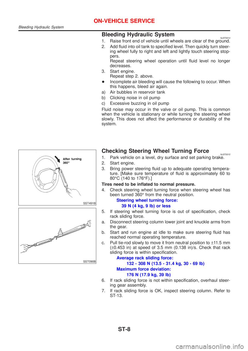
Checking Steering Wheel Turning ForceNJST00151. Park vehicle on a level, dry surface and set parking brake.
2. Start engine.
3. Bring power steering fluid up to adequate operating tempera-
ture. [Make sure temperature of fluid is approximately 60 to
80ÉC (140 to 176ÉF).]
Tires need to be inflated to normal pressure.
4. Check steering wheel turning force when steering wheel has
been turned 360É from the neutral position.
Steering wheel turning force:
39 N (4 kg, 9 lb) or less
5. If steering wheel turning force is out of specification, check
rack sliding force.
a. Disconnect steering column lower joint and knuckle arms from
the gear.
b. Start and run engine at idle to make sure steering fluid has
reached normal operating temperature.
c. Pull tie-rod slowly to move it from neutral position to±11.5 mm
(±0.453 in) at speed of 3.5 mm (0.138 in)/s. Check that rack
sliding force is within specification.
Average rack sliding force:
132 - 308 N (13.5 - 31.4 kg, 30 - 69 lb)
Maximum force deviation:
176 N (17.9 kg, 39 lb)
6. If rack sliding force is not within specification, overhaul steer-
ing gear assembly.
7. If rack sliding force is OK, inspect steering column. Refer to
ST-13.
ON-VEHICLE SERVICE
Bleeding Hydraulic System
ST-8