2001 NISSAN ALMERA N16 power steering
[x] Cancel search: power steeringPage 1820 of 2493

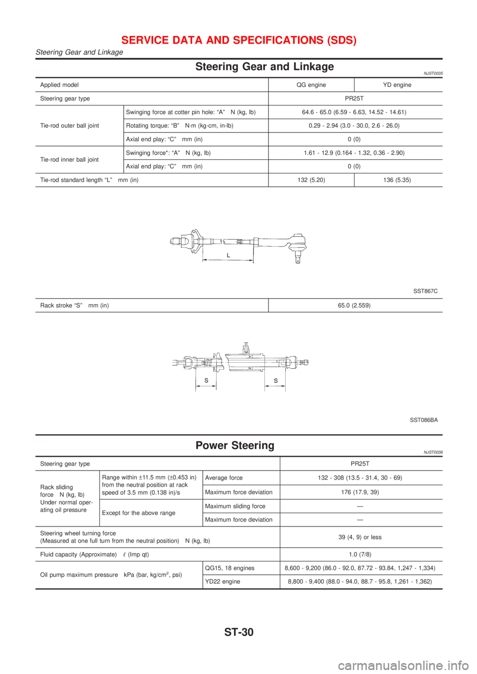
Steering Gear and LinkageNJST0035
Applied modelQG engine YD engine
Steering gear typePR25T
Tie-rod outer ball jointSwinging force at cotter pin hole: ªAº N (kg, lb) 64.6 - 65.0 (6.59 - 6.63, 14.52 - 14.61)
Rotating torque: ªBº N´m (kg-cm, in-lb) 0.29 - 2.94 (3.0 - 30.0, 2.6 - 26.0)
Axial end play: ªCº mm (in) 0 (0)
Tie-rod inner ball jointSwinging force*: ªAº N (kg, lb) 1.61 - 12.9 (0.164 - 1.32, 0.36 - 2.90)
Axial end play: ªCº mm (in) 0 (0)
Tie-rod standard length ªLº mm (in) 132 (5.20) 136 (5.35)
SST867C
Rack stroke ªSº mm (in)65.0 (2.559)
SST086BA
Power SteeringNJST0036
Steering gear typePR25T
Rack sliding
force N (kg, lb)
Under normal oper-
ating oil pressureRange within±11.5 mm (±0.453 in)
from the neutral position at rack
speed of 3.5 mm (0.138 in)/sAverage force 132 - 308 (13.5 - 31.4, 30 - 69)
Maximum force deviation 176 (17.9, 39)
Except for the above rangeMaximum sliding force Ð
Maximum force deviation Ð
Steering wheel turning force
(Measured at one full turn from the neutral position) N (kg, lb)39 (4, 9) or less
Fluid capacity (Approximate)!(Imp qt)1.0 (7/8)
Oil pump maximum pressure kPa (bar, kg/cm
2, psi)QG15, 18 engines 8,600 - 9,200 (86.0 - 92.0, 87.72 - 93.84, 1,247 - 1,334)
YD22 engine 8,800 - 9,400 (88.0 - 94.0, 88.7 - 95.8, 1,261 - 1,362)
SERVICE DATA AND SPECIFICATIONS (SDS)
Steering Gear and Linkage
ST-30
Page 2113 of 2493

ELECTRICAL SYSTEM
SECTION
EL
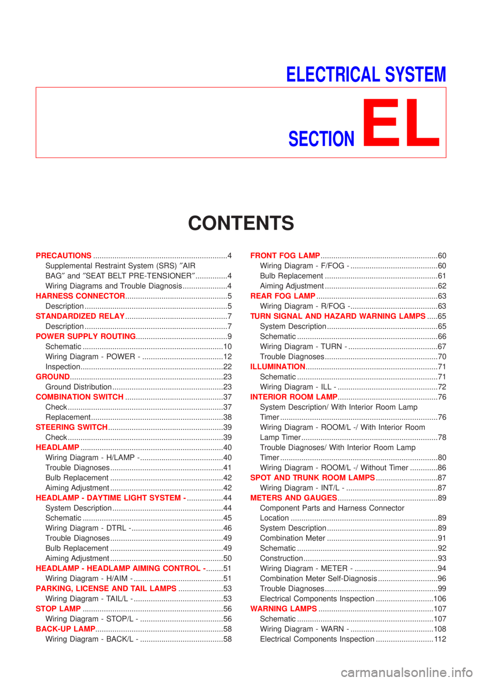
CONTENTS
PRECAUTIONS...............................................................4
Supplemental Restraint System (SRS)²AIR
BAG²and²SEAT BELT PRE-TENSIONER²...............4
Wiring Diagrams and Trouble Diagnosis .....................4
HARNESS CONNECTOR................................................5
Description ...................................................................5
STANDARDIZED RELAY................................................7
Description ...................................................................7
POWER SUPPLY ROUTING...........................................9
Schematic ..................................................................10
Wiring Diagram - POWER - ......................................12
Inspection...................................................................22
GROUND........................................................................23
Ground Distribution ....................................................23
COMBINATION SWITCH..............................................37
Check .........................................................................37
Replacement ..............................................................38
STEERING SWITCH......................................................39
Check .........................................................................39
HEADLAMP...................................................................40
Wiring Diagram - H/LAMP -.......................................40
Trouble Diagnoses.....................................................41
Bulb Replacement .....................................................42
Aiming Adjustment .....................................................42
HEADLAMP - DAYTIME LIGHT SYSTEM -.................44
System Description ....................................................44
Schematic ..................................................................45
Wiring Diagram - DTRL - ...........................................46
Trouble Diagnoses.....................................................49
Bulb Replacement .....................................................49
Aiming Adjustment .....................................................50
HEADLAMP - HEADLAMP AIMING CONTROL -........51
Wiring Diagram - H/AIM - ..........................................51
PARKING, LICENSE AND TAIL LAMPS.....................53
Wiring Diagram - TAIL/L - ..........................................53
STOP LAMP..................................................................56
Wiring Diagram - STOP/L - .......................................56
BACK-UP LAMP............................................................58
Wiring Diagram - BACK/L - .......................................58FRONT FOG LAMP.......................................................60
Wiring Diagram - F/FOG - .........................................60
Bulb Replacement .....................................................61
Aiming Adjustment .....................................................62
REAR FOG LAMP.........................................................63
Wiring Diagram - R/FOG -.........................................63
TURN SIGNAL AND HAZARD WARNING LAMPS.....65
System Description ....................................................65
Schematic ..................................................................66
Wiring Diagram - TURN - ..........................................67
Trouble Diagnoses.....................................................70
ILLUMINATION..............................................................71
Schematic ..................................................................71
Wiring Diagram - ILL - ...............................................72
INTERIOR ROOM LAMP...............................................76
System Description/ With Interior Room Lamp
Timer ..........................................................................76
Wiring Diagram - ROOM/L -/ With Interior Room
Lamp Timer ................................................................78
Trouble Diagnoses/ With Interior Room Lamp
Timer ..........................................................................80
Wiring Diagram - ROOM/L -/ Without Timer .............86
SPOT AND TRUNK ROOM LAMPS.............................87
Wiring Diagram - INT/L - ...........................................87
METERS AND GAUGES...............................................89
Component Parts and Harness Connector
Location .....................................................................89
System Description ....................................................89
Combination Meter ....................................................91
Schematic ..................................................................92
Construction ...............................................................93
Wiring Diagram - METER - .......................................94
Combination Meter Self-Diagnosis ............................96
Trouble Diagnoses.....................................................99
Electrical Components Inspection ...........................106
WARNING LAMPS......................................................107
Schematic ................................................................107
Wiring Diagram - WARN - .......................................108
Electrical Components Inspection ........................... 112
Page 2375 of 2493

for example, when the vehicle is in a tunnel, in a parking lot
inside building, under an elevated superhighway or near strong
power lines, the location may not be detected. Turbulent/
electric weather conditions may also affect positioning perfor-
mance. If something is placed on the antenna, the radio wave
from GPS satellites may not be received.
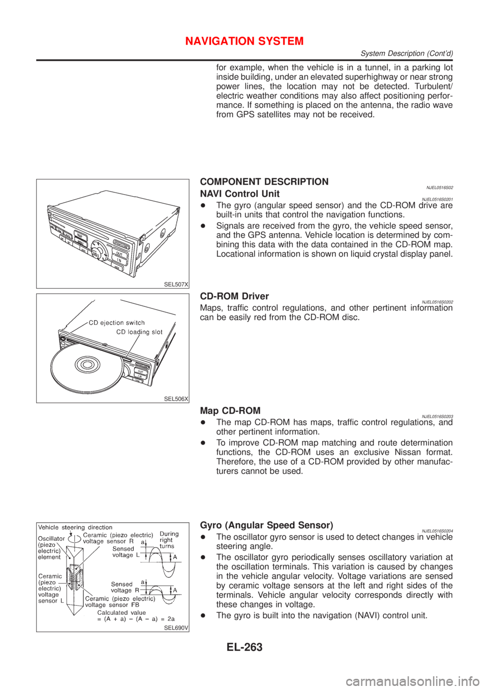
SEL507X
COMPONENT DESCRIPTIONNJEL0516S02NAVI Control UnitNJEL0516S0201+The gyro (angular speed sensor) and the CD-ROM drive are
built-in units that control the navigation functions.
+Signals are received from the gyro, the vehicle speed sensor,
and the GPS antenna. Vehicle location is determined by com-
bining this data with the data contained in the CD-ROM map.
Locational information is shown on liquid crystal display panel.
SEL506X
CD-ROM DriverNJEL0516S0202Maps, traffic control regulations, and other pertinent information
can be easily red from the CD-ROM disc.
Map CD-ROMNJEL0516S0203+The map CD-ROM has maps, traffic control regulations, and
other pertinent information.
+To improve CD-ROM map matching and route determination
functions, the CD-ROM uses an exclusive Nissan format.
Therefore, the use of a CD-ROM provided by other manufac-
turers cannot be used.
SEL690V
Gyro (Angular Speed Sensor)NJEL0516S0204+The oscillator gyro sensor is used to detect changes in vehicle
steering angle.
+The oscillator gyro periodically senses oscillatory variation at
the oscillation terminals. This variation is caused by changes
in the vehicle angular velocity. Voltage variations are sensed
by ceramic voltage sensors at the left and right sides of the
terminals. Vehicle angular velocity corresponds directly with
these changes in voltage.
+The gyro is built into the navigation (NAVI) control unit.
NAVIGATION SYSTEM
System Description (Cont'd)
EL-263
Page 2480 of 2493

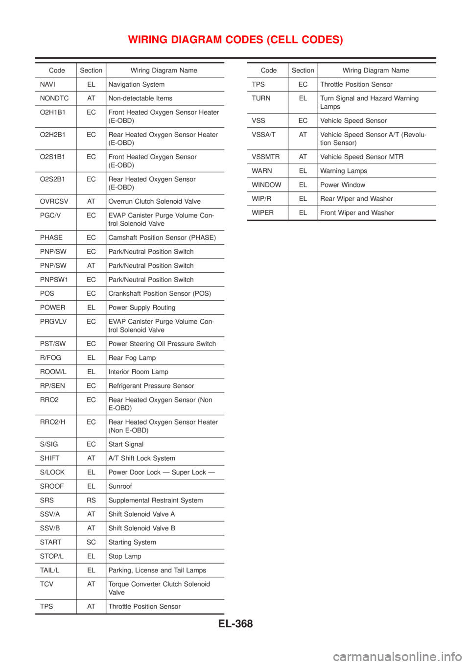
Code Section Wiring Diagram Name
NAVI EL Navigation System
NONDTC AT Non-detectable Items
O2H1B1 EC Front Heated Oxygen Sensor Heater
(E-OBD)
O2H2B1 EC Rear Heated Oxygen Sensor Heater
(E-OBD)
O2S1B1 EC Front Heated Oxygen Sensor
(E-OBD)
O2S2B1 EC Rear Heated Oxygen Sensor
(E-OBD)
OVRCSV AT Overrun Clutch Solenoid Valve
PGC/V EC EVAP Canister Purge Volume Con-
trol Solenoid Valve
PHASE EC Camshaft Position Sensor (PHASE)
PNP/SW EC Park/Neutral Position Switch
PNP/SW AT Park/Neutral Position Switch
PNPSW1 EC Park/Neutral Position Switch
POS EC Crankshaft Position Sensor (POS)
POWER EL Power Supply Routing
PRGVLV EC EVAP Canister Purge Volume Con-
trol Solenoid Valve
PST/SW EC Power Steering Oil Pressure Switch
R/FOG EL Rear Fog Lamp
ROOM/L EL Interior Room Lamp
RP/SEN EC Refrigerant Pressure Sensor
RRO2 EC Rear Heated Oxygen Sensor (Non
E-OBD)
RRO2/H EC Rear Heated Oxygen Sensor Heater
(Non E-OBD)
S/SIG EC Start Signal
SHIFT AT A/T Shift Lock System
S/LOCK EL Power Door Lock Ð Super Lock Ð
SROOF EL Sunroof
SRS RS Supplemental Restraint System
SSV/A AT Shift Solenoid Valve A
SSV/B AT Shift Solenoid Valve B
START SC Starting System
STOP/L EL Stop Lamp
TAIL/L EL Parking, License and Tail Lamps
TCV AT Torque Converter Clutch Solenoid
Valve
TPS AT Throttle Position SensorCode Section Wiring Diagram Name
TPS EC Throttle Position Sensor
TURN EL Turn Signal and Hazard Warning
Lamps
VSS EC Vehicle Speed Sensor
VSSA/T AT Vehicle Speed Sensor A/T (Revolu-
tion Sensor)
VSSMTR AT Vehicle Speed Sensor MTR
WARN EL Warning Lamps
WINDOW EL Power Window
WIP/R EL Rear Wiper and Washer
WIPER EL Front Wiper and Washer
WIRING DIAGRAM CODES (CELL CODES)
EL-368
Page 2486 of 2493

O
Oil pan (engine) .................................. EM-19, 88
Oil pressure (engine) ............................ LC-5, 27
Oil pump (A/T) ......................................... AT-371
Oil pump (engine) ................................. LC-5, 27
Oil pump regulator valve (engine) ......... LC-7, 29
Oil seal replacement (engine) .................. EM-31
On board diagnostic system ............. EC-57, 522
Operating cylinder (clutch) ........................ CL-14
Overdrive control switch .......................... AT-333
Overrun clutch .......................................... AT-399
P
PCV (positive crankcase ventilation) ....... EC-37,
508
PGC/V - Wiring diagram ................. EC-306, 413
PNP/SW - Wiring diagram ...... EC-366, 442, 696
POWER - Wiring diagram ......................... EL-12
PST/SW - Wiring diagram ....................... EC-471
Park/Neutral position switch ... EC-364, 441, 696
Park/neutral position switch (A/T) ............ AT-181
Park/neutral position switch (M/T) ............ MT-21
Parking brake control ................................ BR-47
Parking lamp .............................................. EL-53
Piston assembly ............................... EM-60, 154
Piston pin inspection ........................ EM-54, 144
Piston ring inspection ....................... EM-54, 144
Piston to bore clearance .................. EM-56, 146
Power antenna ........................................ EL-162
Power door lock ....................................... EL-177
Power door mirror .................................... EL-167
Power steering fluid level ............................ ST-7
Power steering gear .................................. ST-15
Power steering hydraulic pressure .............. ST-9
Power steering oil pressure switch ......... EC-470
Power steering system bleeding ................. ST-8
Power supply routing ................................... EL-9
Power window ......................................... EL-169
Precautions (General) .................................. GI-4
Pressure plate - See Clutch cover ............ CL-22
Priming pump .................................. EC-520, 536
Q
Quick-glow system .................................. EC-677
R
RR02 - Wiring diagram .. EC-217, 225, 232, 239,
384
RR02/H - Wiring diagram ............... EC-245, 390
Radiator ............................................... LC-16, 41
Radio - See Audio ................................... EL-149
Rear air spoiler .......................................... BT-47Rear axle (disc brake type) ....................... AX-24
Rear axle ................................................... AX-22
Rear bumper .............................................. BT-10
Rear combination lamp removal and
installation .............................................. BT-47
Rear disc brake .................................. BR-35, 43
Rear door ................................................... BT-16
Rear drum brake ....................................... BR-31
Rear heated oxygen sensor (HO2S)
heater .......................................... EC-243, 389
Rear heated oxygen sensor (HO2S) ..... EC-214,
222, 229, 237, 383
Rear seat belt ............................................ RS-11
Rear seat ................................................... BT-59
Rear suspension ....................................... SU-16
Rear window defogger ............................ EL-138
Rear window .............................................. BT-68
Refrigerant connection precaution .............. HA-3
Refrigerant general precaution ................... HA-2
Refrigerant lines ........................................ HA-97
Refrigeration cycle .................................... HA-13
Release bearing (clutch) ..................... CL-17, 20
Removal and installation (A/T) ................ AT-346
Reverse clutch ......................................... AT-390
Reverse idler shaft (M/T) .............. MT-30, 54, 93
Reverse lamp switch (M/T) - See
Back-up lamp switch (M/T) ................... MT-21
Reverse main gear (M/T) ............. MT-31, 55, 93
Road wheel size ......................................... GI-43
Roof trim .................................................... BT-43
Room lamp - See Interior lamp ................. EL-76
S
S/LOCK - Wiring diagram ................ EL-180, 200
S/SIG - Wiring diagram ........................... EC-461
SAE J1930 terminology list ........................ GI-50
SHIFT - Wiring diagram ........................... AT-336
SROOF - Wiring diagram ........................ EL-165
SRS - See Supplemental Restraint
System ................................................... RS-20
START - Wiring diagram ........................... SC-14
STOP/L - Wiring diagram .......................... EL-56
Seal - See Exterior .................................... BT-47
Seat belt pre-tensioner disposal ............... RS-35
Seat belt pre-tensioner ............................... RS-3
Seat belt, front ............................................ RS-5
Seat belt, rear ............................................ RS-11
Seat, front .................................................. BT-56
Seat, rear ................................................... BT-59
Self-diagnostic results ....................... EC-72, 523
Shift control components (M/T) .... MT-32, 56, 94
Shift fork (M/T) .............................. MT-32, 56, 94
Shift lever .................................................. MT-29
Shift lock system ...................................... AT-335
Shift schedule .......................................... AT-449
Shift solenoid valve A (A/T) ..... AT-202, 207, 220
Shift solenoid valve B (A/T) ............. AT-202, 207
Shock absorber (front) .............................. SU-10
ALPHABETICAL INDEX
IDX-6