2001 NISSAN ALMERA N16 meters
[x] Cancel search: metersPage 1317 of 2493
Diagnostic ProcedureNJAT0080
1 CHECK INPUT SIGNAL
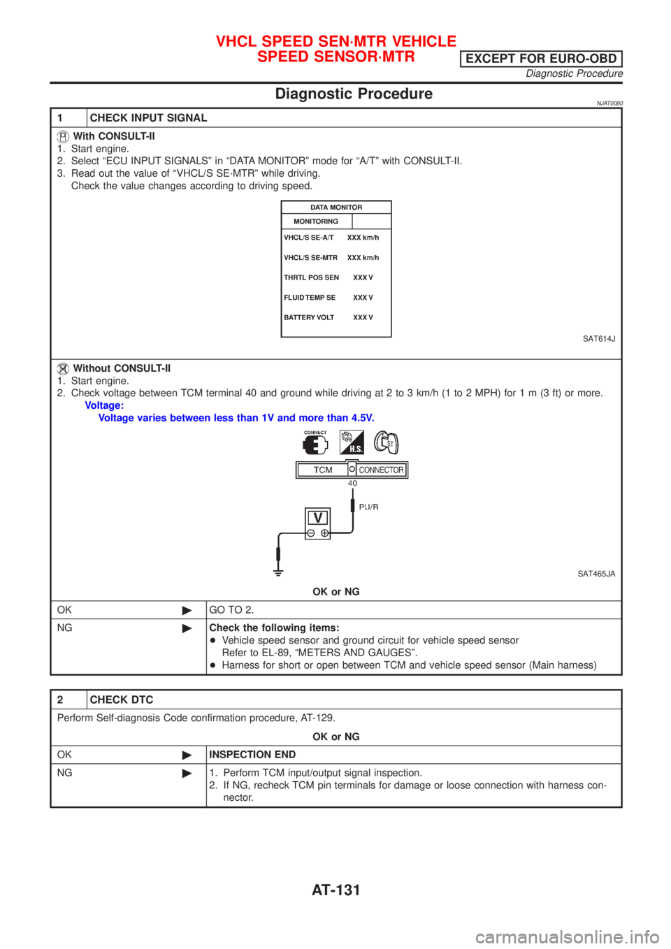
With CONSULT-II
1. Start engine.
2. Select ªECU INPUT SIGNALSº in ªDATA MONITORº mode for ªA/Tº with CONSULT-II.
3. Read out the value of ªVHCL/S SE´MTRº while driving.
Check the value changes according to driving speed.
SAT614J
Without CONSULT-II
1. Start engine.
2. Check voltage between TCM terminal 40 and ground while driving at 2 to 3 km/h (1 to 2 MPH) for1m(3ft)ormore.
Voltage:
Voltage varies between less than 1V and more than 4.5V.
SAT465JA
OK or NG
OK©GO TO 2.
NG©Check the following items:
+Vehicle speed sensor and ground circuit for vehicle speed sensor
Refer to EL-89, ªMETERS AND GAUGESº.
+Harness for short or open between TCM and vehicle speed sensor (Main harness)
2 CHECK DTC
Perform Self-diagnosis Code confirmation procedure, AT-129.
OK or NG
OK©INSPECTION END
NG©1. Perform TCM input/output signal inspection.
2. If NG, recheck TCM pin terminals for damage or loose connection with harness con-
nector.
VHCL SPEED SEN´MTR VEHICLE
SPEED SENSOR´MTR
EXCEPT FOR EURO-OBD
Diagnostic Procedure
AT-131
Page 1467 of 2493
Diagnostic ProcedureNJAT0325
1 CHECK INPUT SIGNAL
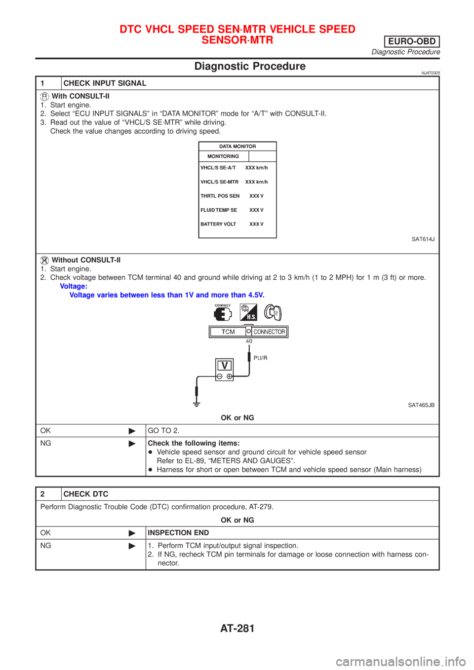
With CONSULT-II
1. Start engine.
2. Select ªECU INPUT SIGNALSº in ªDATA MONITORº mode for ªA/Tº with CONSULT-II.
3. Read out the value of ªVHCL/S SE´MTRº while driving.
Check the value changes according to driving speed.
SAT614J
Without CONSULT-II
1. Start engine.
2. Check voltage between TCM terminal 40 and ground while driving at 2 to 3 km/h (1 to 2 MPH) for1m(3ft)ormore.
Voltage:
Voltage varies between less than 1V and more than 4.5V.
SAT465JB
OK or NG
OK©GO TO 2.
NG©Check the following items:
+Vehicle speed sensor and ground circuit for vehicle speed sensor
Refer to EL-89, ªMETERS AND GAUGESº.
+Harness for short or open between TCM and vehicle speed sensor (Main harness)
2 CHECK DTC
Perform Diagnostic Trouble Code (DTC) confirmation procedure, AT-279.
OK or NG
OK©INSPECTION END
NG©1. Perform TCM input/output signal inspection.
2. If NG, recheck TCM pin terminals for damage or loose connection with harness con-
nector.
DTC VHCL SPEED SEN´MTR VEHICLE SPEED
SENSOR´MTR
EURO-OBD
Diagnostic Procedure
AT-281
Page 1475 of 2493

2 CHECK TCM GROUND CIRCUIT
1. Turn ignition switch to ªOFFº position.
2. Disconnect TCM harness connector.
3. Check continuity between TCM terminals 25, 48 and ground.
SAT468J
Continuity should exist.
If OK, check harness for short to ground and short to power.
OK or NG
OK©GO TO 3.
NG©Repair open circuit or short to ground or short to power in harness or connectors. Refer
to ªWiring Diagram Ð AT Ð MAINº, AT-121.
3 CHECK LAMP CIRCUIT
1. Turn ignition switch to ªOFFº position.
2. Check resistance between TCM terminals 13 and 10.
Resistance: 50 - 100W
SAT469JB
3. Reinstall any part removed.
OK or NG
OK©GO TO 4.
NG©Check the following items:
+O/D OFF indicator lamp.
Refer to EL-89, ªMETERS AND GAUGESº.
+Harness and fuse for short or open between ignition switch and O/D OFF indicator
lamp (Main harness)
Refer to EL-10, ªPOWER SUPPLY ROUTINGº.
+Harness for short or open between O/D OFF indicator lamp and TCM.
TROUBLE DIAGNOSES FOR SYMPTOMS
1. O/D OFF Indicator Lamp Does Not Come On (Cont'd)
AT-289
Page 2113 of 2493
ELECTRICAL SYSTEM
SECTION
EL
CONTENTS
PRECAUTIONS...............................................................4
Supplemental Restraint System (SRS)²AIR
BAG²and²SEAT BELT PRE-TENSIONER²...............4
Wiring Diagrams and Trouble Diagnosis .....................4
HARNESS CONNECTOR................................................5
Description ...................................................................5
STANDARDIZED RELAY................................................7
Description ...................................................................7
POWER SUPPLY ROUTING...........................................9
Schematic ..................................................................10
Wiring Diagram - POWER - ......................................12
Inspection...................................................................22
GROUND........................................................................23
Ground Distribution ....................................................23
COMBINATION SWITCH..............................................37
Check .........................................................................37
Replacement ..............................................................38
STEERING SWITCH......................................................39
Check .........................................................................39
HEADLAMP...................................................................40
Wiring Diagram - H/LAMP -.......................................40
Trouble Diagnoses.....................................................41
Bulb Replacement .....................................................42
Aiming Adjustment .....................................................42
HEADLAMP - DAYTIME LIGHT SYSTEM -.................44
System Description ....................................................44
Schematic ..................................................................45
Wiring Diagram - DTRL - ...........................................46
Trouble Diagnoses.....................................................49
Bulb Replacement .....................................................49
Aiming Adjustment .....................................................50
HEADLAMP - HEADLAMP AIMING CONTROL -........51
Wiring Diagram - H/AIM - ..........................................51
PARKING, LICENSE AND TAIL LAMPS.....................53
Wiring Diagram - TAIL/L - ..........................................53
STOP LAMP..................................................................56
Wiring Diagram - STOP/L - .......................................56
BACK-UP LAMP............................................................58
Wiring Diagram - BACK/L - .......................................58FRONT FOG LAMP.......................................................60
Wiring Diagram - F/FOG - .........................................60
Bulb Replacement .....................................................61
Aiming Adjustment .....................................................62
REAR FOG LAMP.........................................................63
Wiring Diagram - R/FOG -.........................................63
TURN SIGNAL AND HAZARD WARNING LAMPS.....65
System Description ....................................................65
Schematic ..................................................................66
Wiring Diagram - TURN - ..........................................67
Trouble Diagnoses.....................................................70
ILLUMINATION..............................................................71
Schematic ..................................................................71
Wiring Diagram - ILL - ...............................................72
INTERIOR ROOM LAMP...............................................76
System Description/ With Interior Room Lamp
Timer ..........................................................................76
Wiring Diagram - ROOM/L -/ With Interior Room
Lamp Timer ................................................................78
Trouble Diagnoses/ With Interior Room Lamp
Timer ..........................................................................80
Wiring Diagram - ROOM/L -/ Without Timer .............86
SPOT AND TRUNK ROOM LAMPS.............................87
Wiring Diagram - INT/L - ...........................................87
METERS AND GAUGES...............................................89
Component Parts and Harness Connector
Location .....................................................................89
System Description ....................................................89
Combination Meter ....................................................91
Schematic ..................................................................92
Construction ...............................................................93
Wiring Diagram - METER - .......................................94
Combination Meter Self-Diagnosis ............................96
Trouble Diagnoses.....................................................99
Electrical Components Inspection ...........................106
WARNING LAMPS......................................................107
Schematic ................................................................107
Wiring Diagram - WARN - .......................................108
Electrical Components Inspection ........................... 112
Page 2201 of 2493
Component Parts and Harness Connector
Location
NJEL0441For details, refer to ªELECTRICAL UNIT LOCATIONº (EL-319) and
ªHARNESS LAYOUTº (EL-324).
System DescriptionNJEL0442UNIFIED CONTROL METERNJEL0442S01+Speedometer, odo/trip meter, tachometer, fuel gauge and water temperature gauge are controlled totally
by control unit built-in combination meter.
+Digital meter is adopted for odo/trip meter.*
*The record of the odo meter is kept even if the battery cable is disconnected. The record of the trip meter
is erased when the battery cable is disconnected.
+Odo/trip meter segment can be checked in diagnosis mode.
+Meter/gauge can be checked in diagnosis mode.
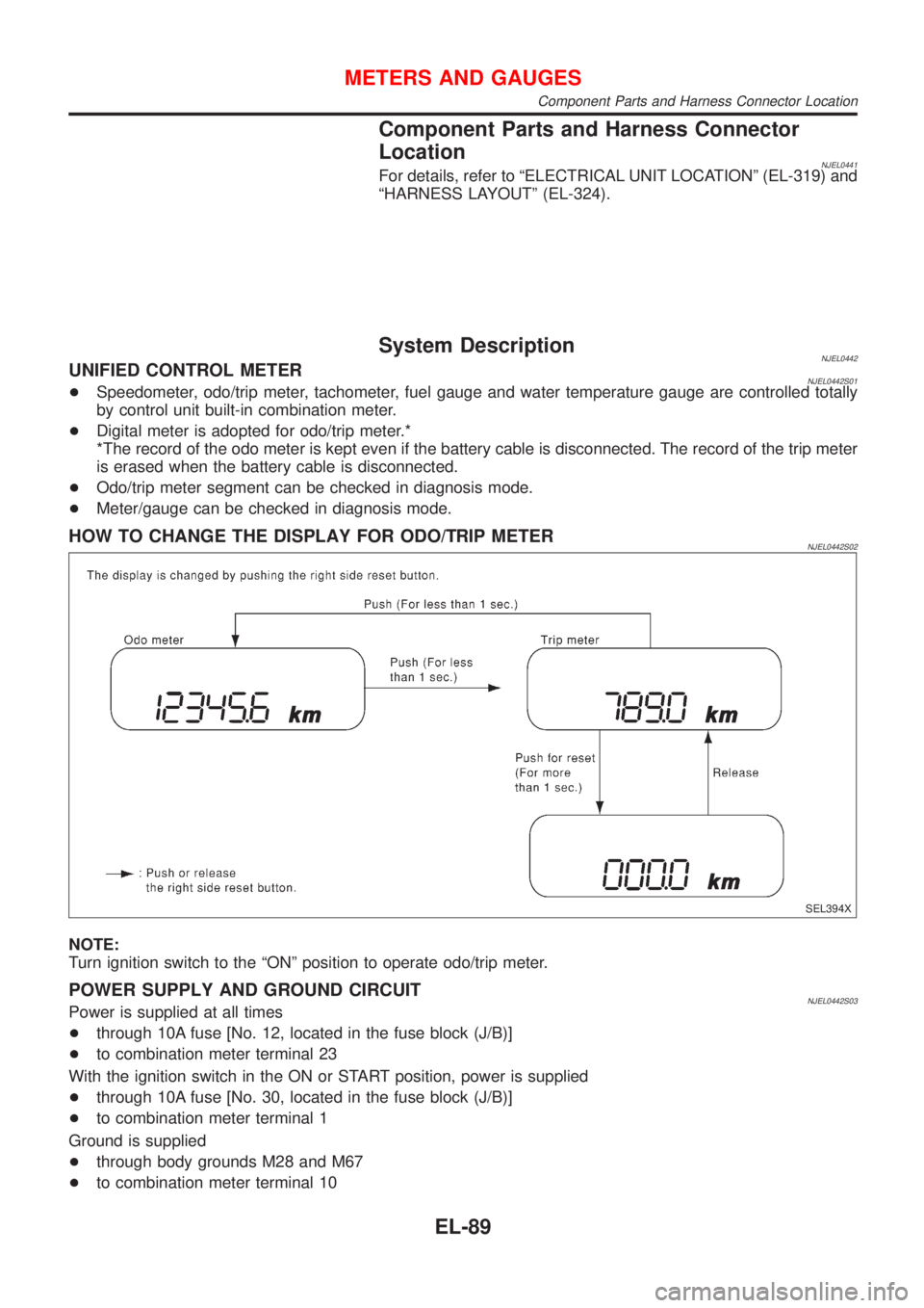
HOW TO CHANGE THE DISPLAY FOR ODO/TRIP METERNJEL0442S02
SEL394X
NOTE:
Turn ignition switch to the ªONº position to operate odo/trip meter.
POWER SUPPLY AND GROUND CIRCUITNJEL0442S03Power is supplied at all times
+through 10A fuse [No. 12, located in the fuse block (J/B)]
+to combination meter terminal 23
With the ignition switch in the ON or START position, power is supplied
+through 10A fuse [No. 30, located in the fuse block (J/B)]
+to combination meter terminal 1
Ground is supplied
+through body grounds M28 and M67
+to combination meter terminal 10
METERS AND GAUGES
Component Parts and Harness Connector Location
EL-89
Page 2202 of 2493
WATER TEMPERATURE GAUGENJEL0442S04The water temperature gauge indicates the engine coolant temperature. The reading on the gauge is based
on the resistance of the thermal transmitter.
As the temperature of the coolant increases, the resistance of the thermal transmitter decreases. A variable
ground is supplied to terminal 20 of the combination meter for the water temperature gauge. The needle on
the gauge moves from ªCº to ªHº.
TACHOMETERNJEL0442S05The tachometer indicates engine speed in revolutions per minute (rpm).
The tachometer is regulated by a signal
+from terminal 32 (Gasoline engine models) or 439 (Diesel engine models) of the ECM
+to combination meter terminal 22 for the tachometer.
FUEL GAUGENJEL0442S06The fuel gauge indicates the approximate fuel level in the fuel tank.
The fuel gauge is regulated by a variable ground signal supplied
+from body grounds M28 and M67
+through terminals 9 and 10 of combination meter,
+through terminal 1 of the fuel level sensor unit and
+through terminal 4 of the fuel level sensor unit
+to combination meter terminal 24 for the fuel gauge.
SPEEDOMETERNJEL0442S07The combination meter provides a voltage signal to the vehicle speed sensor for the speedometer.
The voltage is supplied
+from combination meter terminal 5 for the speedometer
+to terminal 1 of the vehicle speed sensor.
Ground is supplied
+from body grounds M28 and M67
+through terminals 10 and 11 of combination meter
+to teminal 2 of the vehicle speed sensor.
The speedometer converts the voltage into the vehicle speed displayed.
METERS AND GAUGES
System Description (Cont'd)
EL-90
Page 2203 of 2493
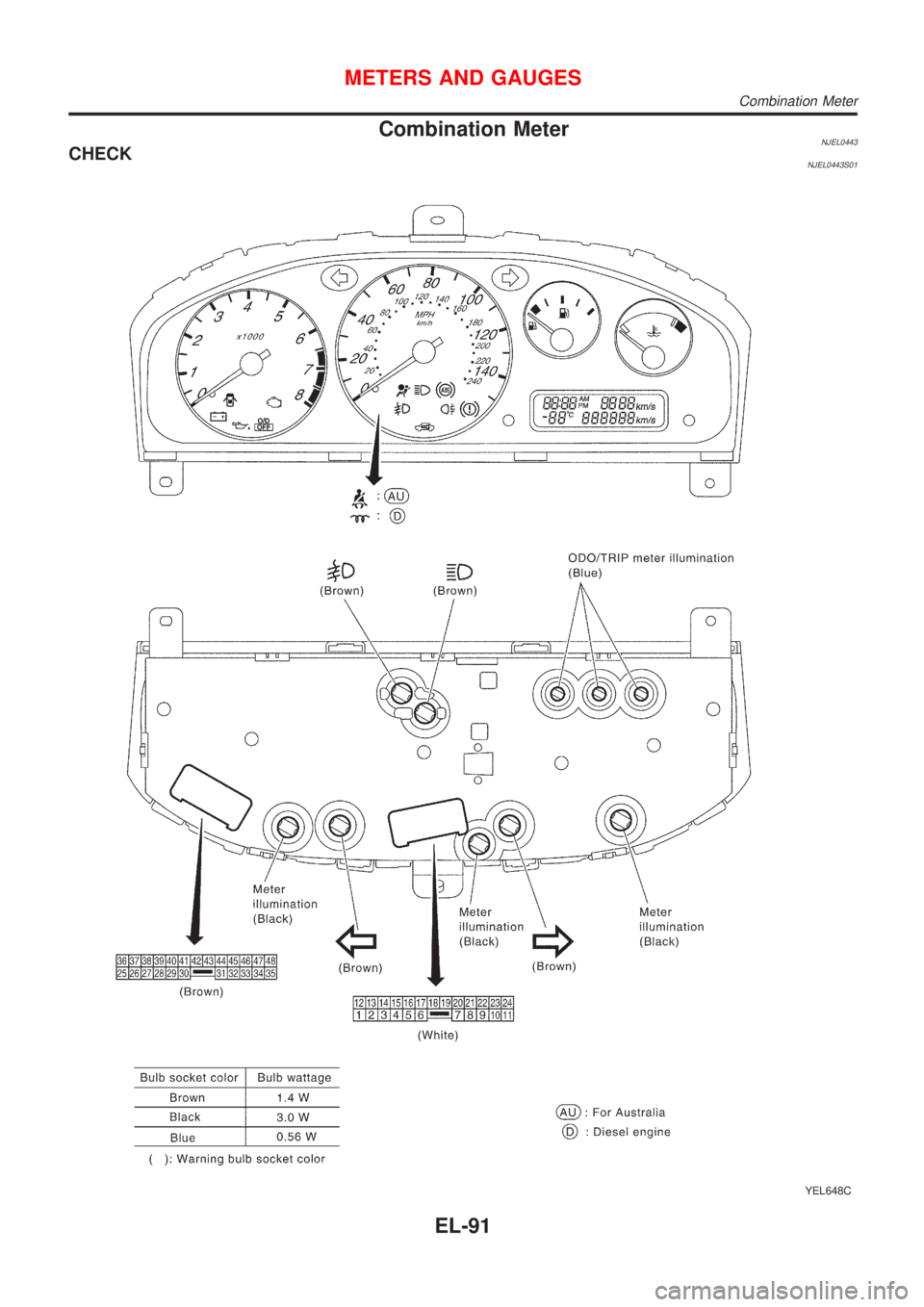
Combination MeterNJEL0443CHECKNJEL0443S01
YEL648C
METERS AND GAUGES
Combination Meter
EL-91
Page 2204 of 2493
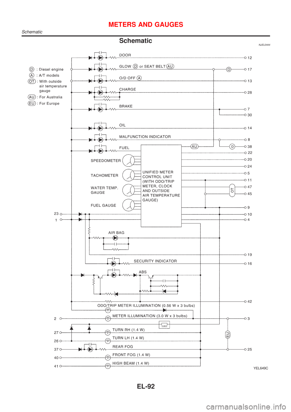
SchematicNJEL0444
YEL649C
METERS AND GAUGES
Schematic
EL-92