2001 NISSAN ALMERA N16 meters
[x] Cancel search: metersPage 37 of 2493

NJGI0007
Function and System ApplicationNJGI0007S05
Diagnostic
test modeFunction ENGINE A/T ABS AIR BAGSMART
EN-
TRANCENATS*1NAVIGA-
TION
Work sup-
portThis mode enables a technician to
adjust some devices faster and
more accurate by following the indi-
cations on CONSULT-II.x ÐÐÐXÐÐ
Self-diag-
nostic
resultsSelf-diagnostic results can be read
and erased quickly.x x x xÐxÐ
Trouble
diagnostic
recordCurrent self-diagnostic results and
all trouble diagnostic records previ-
ously stored can be read.ÐÐÐ x ÐÐÐ
ECU dis-
criminated
No.Classification number of a replace-
ment ECU can be read to prevent
an incorrect ECU from being
installed.ÐÐÐ x ÐÐÐ
Data monitorInput/Output data in the ECU
(ECM) can be read.x x xÐxÐÐ
Data monitor
(Spec.)The specified values will be dis-
played when an OK/NG judgement
is difficult for the DATA MONITOR
items by Barchart and Line Graph.X ÐÐÐÐÐÐ
DTC work
supportThis mode enables a technician to
set operating conditions to confirm
self-diagnoses status/results.x*2x ÐÐÐÐÐ
Active testDiagnostic Test Mode in which
CONSULT-II drives some actuators
apart from the ECMs and also
shifts some parameters in a speci-
fied range.xÐxÐxÐÐ
ECU (ECM)
part numberECU (ECM) part number can be
read.x x x ÐÐÐÐ
Control unit
initializationAll registered ignition key IDs in
NATS components can be initial-
ized and new IDs can be regis-
tered.ÐÐÐÐÐ x Ð
PIN
INITIALIZA-
TIONNavigation system will be locked
when the vehicle's owner enters
the wrong PIN five consecutive
times.
To release the lock, use ªPIN INI-
TIALIZATIONº.ÐÐÐÐÐÐ x
NAVI ID
INITIALIZA-
TIONIn nomal times regulation codes are
being communicated between Navi-
gation Control Unit and Dongle
Control Unit.
Use ªNAVI ID INITIALIZATIONº to
match the codes when either one
has been replaced due to break-
down or etc.ÐÐÐÐÐÐ x
x: Applicable
*1: NATS (Nissan Anti-Theft System)
*2: For models with Euro-OBD system
CONSULT-II CHECKING SYSTEM
Function and System Application
GI-35
Page 61 of 2493

Engine and Emission Control Maintenance
(Gasoline engine)
NJMA0005S04Abbreviations: I = Inspect and correct or replace as necessary, R = Replace, A = Adjust, C = Clean, E = Check and correct the
engine coolant mixture ratio.
MAINTENANCE OPERATIONMAINTENANCE INTERVAL
Refer-
ence
page Perform either at number of kilometers (miles)
or months, whichever comes first.km x 1,000
(Miles x 1,000)
Months1
(0.6)
Ð10
(6)
620
(12)
1230
(18)
1840
(24)
2450
(30)
3060
(36)
3670
(42)
4280
(48)
48
Underhood and under vehicle
Torque of manifolds & exhaust tube nuts*1 I Ð
Intake & exhaust valve clearance*2AAAAEM-42
Drive belts I*1 I*1 I I*1 I EM-15
Engine oil (Use API SE, SF, SG, SH or SJ
oil.)HRRRRRRRRLC-8
Engine oil filter (Use Part No. 15208 65F01 or
equivalent)HRRRRRRRRLC-9
Engine coolant (Use Nissan genuine engine
coolant L2N or equivalent in its quality.)See NOTE (1) E R LC-17
Cooling systemIIIILC-12
Fuel linesI I FE-5
Air cleaner filter (Dry paper type)HCCCRCCCREM-0
Air cleaner filter (Viscous paper type)HR R EM-17
Fuel filter See NOTE (2) FE-9
Positive crankcase ventilation (PCV) system I*1 I*1 I*1 I*1 EC-37
Spark plugs (Conventional type)*3 R R EM-18
Spark plugs (Conventional type, For leaded
fuel)*1I R I R I R I R EM-18
Spark plugs (Conventional type, For unleaded
fuel)*1I I I R I I I R EM-18
EVAP vapor lines (With carbon canister) I I EC-34
Vacuum hoses & connections*1IIIIEC-27
Heated oxygen sensor (Exhaust gas sensor) I I EC-176
NOTE:
HMaintenance items with ªHº should be performed more frequently according to ªMaintenance Under Severe Driving Con-
ditionsº.
(1) Use Nissan genuine engine coolant, or equivalent in its quality, in order to avoid possible aluminum corrosion within the
engine cooling system caused by the use of non-genuine engine coolant. After first replacement, replace every 40,000 km (24,
000 miles) or 24 months.
(2) Maintenance-free item. For service procedures, refer to FE section.
*1: Models without three way catalyst
*2: For models with three way catalyst, periodic maintenance is not required. However, if valve noise increases, check valve clearance.
*3: Models with three way catalyst
PERIODIC MAINTENANCE (EXCEPT FOR EUROPE)
Engine and Emission Control Maintenance (Gasoline engine)
MA-5
Page 150 of 2493

Cylinder BlockNJEM0033Unit: mm (in)
SEM171D
QG15DE QG18DE
Limit
Standard
Surface flatness Less than 0.03 (0.0012) 0.1 (0.004)
Height ªHº (nominal) 213.95 - 214.05 (8.4232 - 8.4271) Ð
Cylinder bore
inner diameterStandardGrade No. 1 73.600 - 73.610 (2.8976 - 2.8976) 80.000 - 80.010 (3.1496 - 3.1500)
0.2 (0.008) Grade No. 2 73.610 - 73.620 (2.8980 - 2.8984) 80.010 - 80.020 (3.1500 - 3.1504)
Grade No. 3 73.620 - 73.630 (2.8984 - 2.8988) 80.020 - 80.030 (3.1504 - 3.1508)
Out-of-round (X þ Y) Less than 0.015 (0.0006) Ð
Taper (A þ B) Less than 0.01 (0.0004) Ð
Difference in inner diameter between cylinders 0.05 (0.0020) 0.2 (0.008)
SERVICE DATA AND SPECIFICATIONS (SDS)QG
Cylinder Block
EM-72
Page 244 of 2493

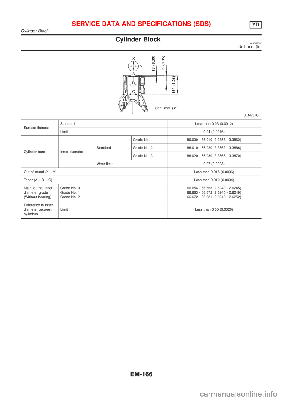
Cylinder BlockNJEM0081Unit: mm (in)
JEM207G
Surface flatnessStandardLess than 0.03 (0.0012)
Limit0.04 (0.0016)
Cylinder bore Inner diameterStandardGrade No. 1 86.000 - 86.010 (3.3858 - 3.3862)
Grade No. 2 86.010 - 86.020 (3.3862 - 3.3866)
Grade No. 3 86.020 - 86.030 (3.3866 - 3.3870)
Wear limit 0.07 (0.0028)
Out-of-round (X þ Y)Less than 0.015 (0.0006)
Taper (AþBþC)Less than 0.010 (0.0004)
Main journal inner
diameter grade
(Without bearing)Grade No. 0
Grade No. 1
Grade No. 266.654 - 66.663 (2.6242 - 2.6245)
66.663 - 66.672 (2.6245 - 2.6249)
66.672 - 66.681 (2.6249 - 2.6252)
Difference in inner
diameter between
cylindersLimitLess than 0.05 (0.0020)
SERVICE DATA AND SPECIFICATIONS (SDS)YD
Cylinder Block
EM-166
Page 276 of 2493

DISASSEMBLY AND ASSEMBLYNJLC0044
JLC285B
JLC286B
JLC355B
OIL PUMP INSPECTIONNJLC0045+Install the inner rotor and outer rotor with the punched
marks on the pump cover side.
Using a feeler gauge, straightedge and micrometers, check the
following clearances:
Unit: mm (in)
Body to outer rotor radial clearance10.114 - 0.260 (0.0045 - 0.0102)
Inner rotor to outer rotor tip clearance
2Below 0.18 (0.0071)
Body to inner rotor axial clearance30.050 - 0.090 (0.0020 - 0.0035)
Body to outer rotor axial clearance40.030 - 0.190 (0.0012 - 0.0075)
Inner rotor to brazed portion of hous-
ing clearance50.045 - 0.091 (0.0018 - 0.0036)
+If the tip clearance (2) exceeds the limit, replace rotor set.
+If body to rotor clearances (1, 3, 4, 5) exceed the limit,
replace oil pump body assembly.
ENGINE LUBRICATION SYSTEMYD
Oil Pump (Cont'd)
LC-28
Page 379 of 2493

ItemDIAGNOSTIC TEST MODE
WORK
SUP-
PORTSELF-DIAGNOSTIC
RESULTS
D ATA
MONI-
TORD ATA
MONI-
TOR
(SPEC)ACTIVE
TESTDTC & SRT
CONFIRMATION
DTC*1FREEZE
FRAME
DATA*2SRT
STA-
TUSDTC
WORK
SUP-
PORT
ENGINE CONTROL COMPONENT PARTS
OUT-
PUTInjectors X X X
Power transistor (Ignition tim-
ing)X*3
(misfire)XXX
IACV-AAC valve X X*3 X X X
Intake valve timing control
solenoid valveXXX
EVAP canister purge volume
control solenoid valveX*3 X X X
Air conditioner relay X X
Fuel pump relay X X X X
EGR volume control valve*4 X*3 X X X X*3
Heated oxygen sensor 1
heater (front)X*3 X X X*3
Heated oxygen sensor 2
heater (rear)X*3 X X X*3
Cooling fan X X X
Calculated load value X X X
X: Applicable
*1: This item includes 1st trip DTCs.
*2: This mode includes 1st trip freeze frame data or freeze frame data. The items appear on CONSULT-II screen in freeze frame data
mode only if a 1st trip DTC or DTC is detected. For details, refer to EC-59, EC-70.
*3: Not applicable for models without Euro-OBD system
*4: If so equipped
FUNCTIONNJEC0034S03
Diagnostic test mode Function
Work supportThis mode enables a technician to adjust some devices faster and more accurately by following the
indications on the CONSULT-II unit.
Self-diagnostic resultsSelf-diagnostic results such as 1st trip DTC, DTCs and 1st trip freeze frame data or freeze frame
data can be read and erased quickly.*1
Data monitor Input/Output data in the ECM can be read.
Data monitor (spec)Input/Output specifications of the basic fuel schedule, AFM, A/F feedback control value and the
other data monitor items can be read.
Active testDiagnostic Test Mode in which CONSULT-II drives some actuators apart from the ECMs and also
shifts some parameters in a specified range.
DTC and SRT confirmation The status of system monitoring tests and the self-diagnosis status/result can be confirmed.
ECM part number ECM part numbers can be read.
*1 The following emission-related diagnostic information is cleared when the ECM memory is erased.
1) Diagnostic trouble codes
2) 1st trip diagnostic trouble codes
3) Freeze frame data
4) 1st trip freeze frame data
ON BOARD DIAGNOSTIC SYSTEM DESCRIPTIONQG
CONSULT-II (Cont'd)
EC-83
Page 596 of 2493

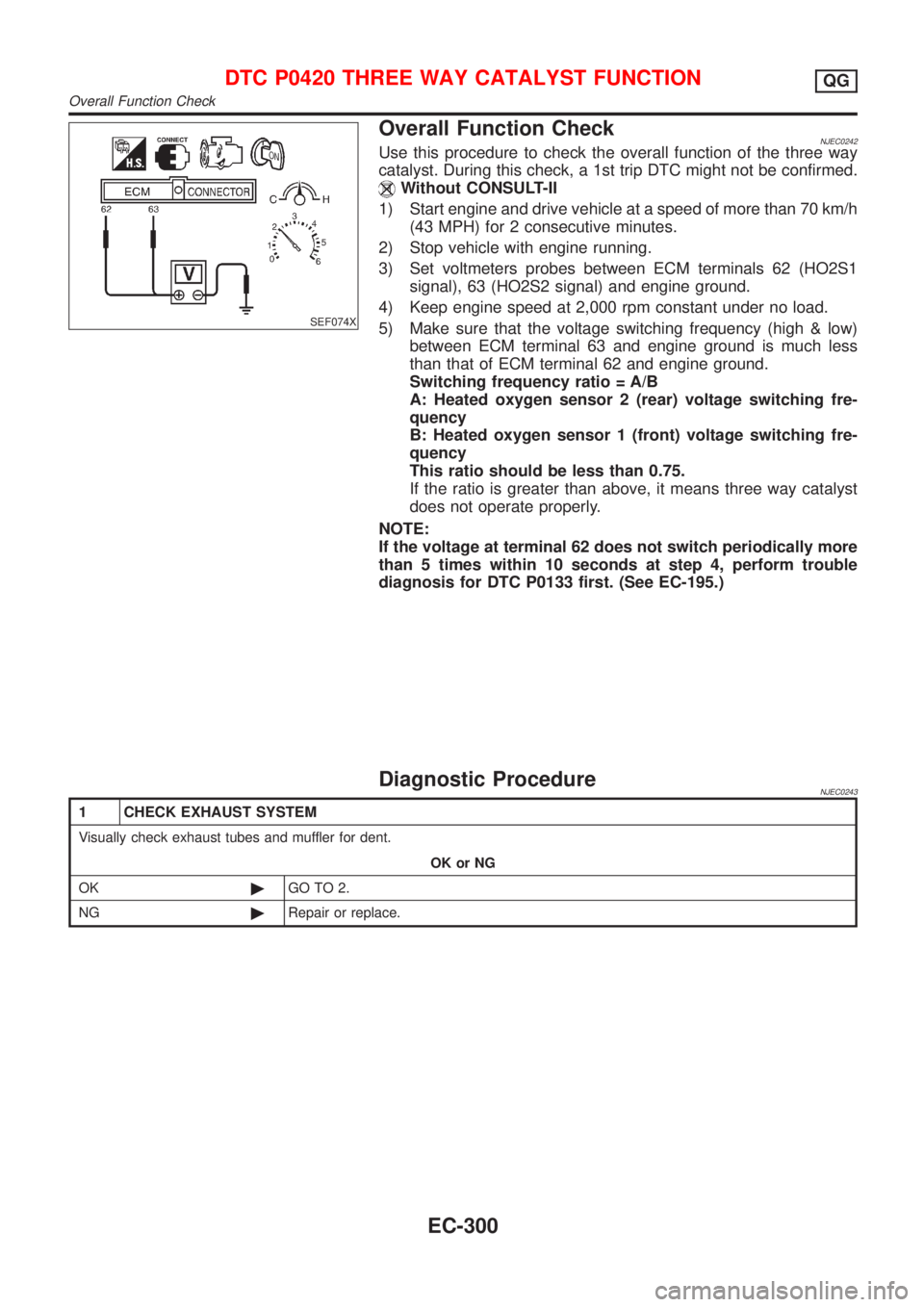
SEF074X
Overall Function CheckNJEC0242Use this procedure to check the overall function of the three way
catalyst. During this check, a 1st trip DTC might not be confirmed.
Without CONSULT-II
1) Start engine and drive vehicle at a speed of more than 70 km/h
(43 MPH) for 2 consecutive minutes.
2) Stop vehicle with engine running.
3) Set voltmeters probes between ECM terminals 62 (HO2S1
signal), 63 (HO2S2 signal) and engine ground.
4) Keep engine speed at 2,000 rpm constant under no load.
5) Make sure that the voltage switching frequency (high & low)
between ECM terminal 63 and engine ground is much less
than that of ECM terminal 62 and engine ground.
Switching frequency ratio = A/B
A: Heated oxygen sensor 2 (rear) voltage switching fre-
quency
B: Heated oxygen sensor 1 (front) voltage switching fre-
quency
This ratio should be less than 0.75.
If the ratio is greater than above, it means three way catalyst
does not operate properly.
NOTE:
If the voltage at terminal 62 does not switch periodically more
than 5 times within 10 seconds at step 4, perform trouble
diagnosis for DTC P0133 first. (See EC-195.)
Diagnostic ProcedureNJEC0243
1 CHECK EXHAUST SYSTEM
Visually check exhaust tubes and muffler for dent.
OK or NG
OK©GO TO 2.
NG©Repair or replace.
DTC P0420 THREE WAY CATALYST FUNCTIONQG
Overall Function Check
EC-300
Page 608 of 2493

Diagnostic ProcedureNJEC0278
1 CHECK INPUT SIGNAL CIRCUIT
1. Turn ignition switch ªOFFº.
2. Disconnect ECM harness connector and combination meter harness connector.
3. Check harness continuity between ECM terminal 86 and meter terminal 4.
Refer to wiring diagram.
Continuity should exist.
4. Also check harness for short to ground and short to power.
OK or NG
OK©GO TO 3.
NG©GO TO 2.
2 DETECT MALFUNCTIONING PART
Check the following.
+Harness connectors M63, F102
+Harness for open or short between ECM and combination meter
©Repair open circuit or short to ground or short to power in harness or connectors.
3 CHECK SPEEDOMETER FUNCTION
Make sure that speedometer functions properly.
OK or NG
OK©GO TO 5.
NG©GO TO 4.
4 CHECK SPEEDOMETER CIRCUIT
Check the following.
+Harness connectors M63, F102
+Harness connectors M169, F113
+Harness for open or short between combination meter and vehicle speed sensor
OK©Check combination meter and vehicle speed sensor. Refer to EL-89, ªMETERS AND
GAUGESº.
NG©Repair open circuit or short to ground or short to power in harness or connectors.
5 CHECK INTERMITTENT INCIDENT
Perform ªTROUBLE DIAGNOSIS FOR INTERMITTENT INCIDENTº, EC-144.
©INSPECTION END
DTC P0500 VEHICLE SPEED SENSOR (VSS)QG
Diagnostic Procedure
EC-312