2001 NISSAN ALMERA N16 coolant temperature
[x] Cancel search: coolant temperaturePage 293 of 2493
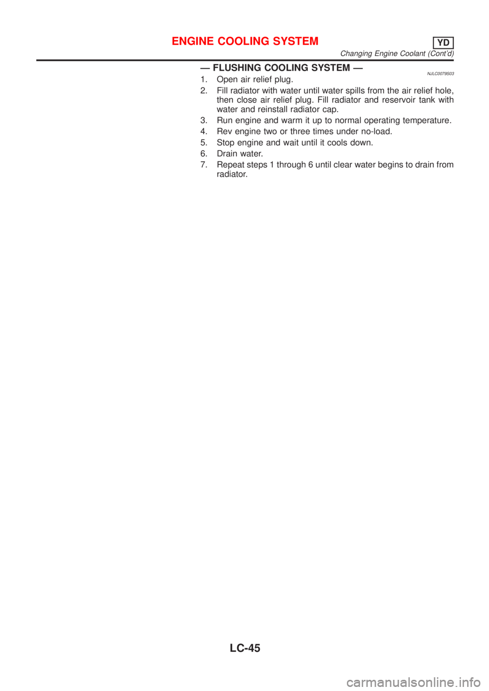
Ð FLUSHING COOLING SYSTEM ÐNJLC0079S031. Open air relief plug.
2. Fill radiator with water until water spills from the air relief hole,
then close air relief plug. Fill radiator and reservoir tank with
water and reinstall radiator cap.
3. Run engine and warm it up to normal operating temperature.
4. Rev engine two or three times under no-load.
5. Stop engine and wait until it cools down.
6. Drain water.
7. Repeat steps 1 through 6 until clear water begins to drain from
radiator.
ENGINE COOLING SYSTEMYD
Changing Engine Coolant (Cont'd)
LC-45
Page 295 of 2493
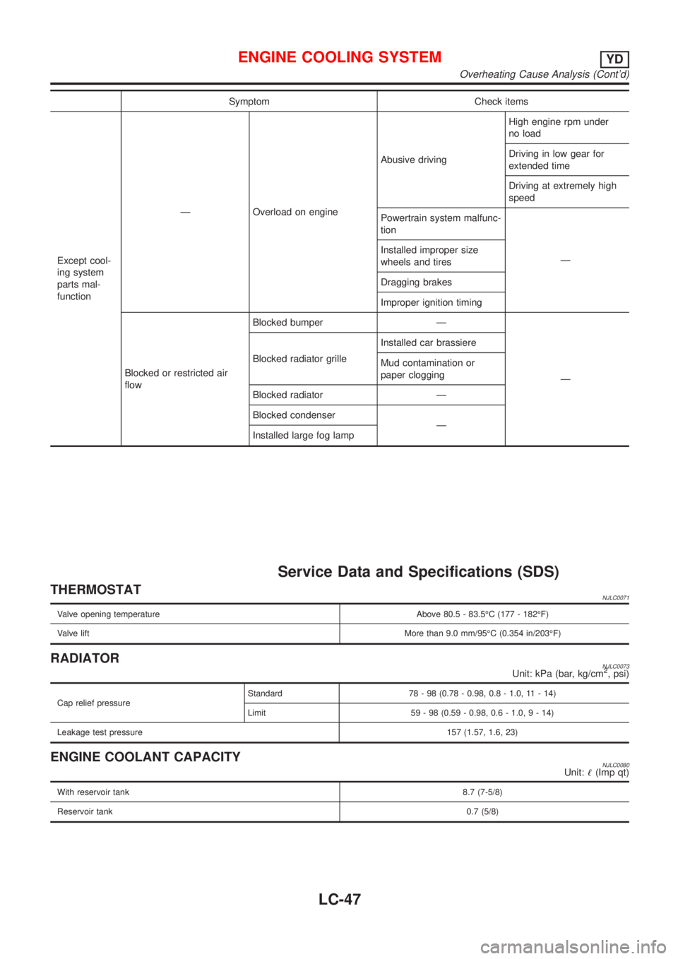
Symptom Check items
Except cool-
ing system
parts mal-
functionÐ Overload on engineAbusive drivingHigh engine rpm under
no load
Driving in low gear for
extended time
Driving at extremely high
speed
Powertrain system malfunc-
tion
Ð Installed improper size
wheels and tires
Dragging brakes
Improper ignition timing
Blocked or restricted air
flowBlocked bumper Ð
Ð Blocked radiator grilleInstalled car brassiere
Mud contamination or
paper clogging
Blocked radiator Ð
Blocked condenser
Ð
Installed large fog lamp
Service Data and Specifications (SDS)
THERMOSTATNJLC0071
Valve opening temperature Above 80.5 - 83.5ÉC (177 - 182ÉF)
Valve liftMore than 9.0 mm/95ÉC (0.354 in/203ÉF)
RADIATORNJLC0073Unit: kPa (bar, kg/cm2, psi)
Cap relief pressureStandard 78 - 98 (0.78 - 0.98, 0.8 - 1.0, 11 - 14)
Limit 59 - 98 (0.59 - 0.98, 0.6 - 1.0,9-14)
Leakage test pressure157 (1.57, 1.6, 23)
ENGINE COOLANT CAPACITYNJLC0080Unit:!(Imp qt)
With reservoir tank8.7 (7-5/8)
Reservoir tank0.7 (5/8)
ENGINE COOLING SYSTEMYD
Overheating Cause Analysis (Cont'd)
LC-47
Page 298 of 2493
CONSULT-II Reference Value in Data Monitor
Mode ........................................................................152
ECM Terminals and Reference Value .....................152
On Board Diagnosis Logic.......................................152
Fail-safe Mode .........................................................153
DTC Confirmation Procedure ..................................153
Wiring Diagram ........................................................154
Diagnostic Procedure ..............................................155
Component Inspection .............................................157
DTC P0110 INTAKE AIR TEMPERATURE
SENSOR......................................................................158
Component Description ...........................................158
On Board Diagnosis Logic.......................................158
DTC Confirmation Procedure ..................................158
Wiring Diagram ........................................................160
Diagnostic Procedure ..............................................161
Component Inspection .............................................162
DTC P0115 ENGINE COOLANT TEMPERATURE
SENSOR (ECTS).........................................................163
Component Description ...........................................163
CONSULT-II Reference Value in Data Monitor
Mode ........................................................................163
On Board Diagnosis Logic.......................................163
Fail-safe Mode .........................................................164
DTC Confirmation Procedure ..................................164
Wiring Diagram ........................................................165
Diagnostic Procedure ..............................................166
Component Inspection .............................................167
DTC P0120 THROTTLE POSITION SENSOR...........168
Component Description ...........................................168
CONSULT-II Reference Value in Data Monitor
Mode ........................................................................168
ECM Terminals and Reference Value .....................169
On Board Diagnosis Logic.......................................169
Fail-safe Mode .........................................................169
DTC Confirmation Procedure ..................................169
Wiring Diagram ........................................................171
Diagnostic Procedure ..............................................172
Component Inspection .............................................174
DTC P0130 HEATED OXYGEN SENSOR 1
(FRONT) (CIRCUIT).....................................................176
Component Description ...........................................176
CONSULT-II Reference Value in Data Monitor
Mode ........................................................................176
ECM Terminals and Reference Value .....................176
On Board Diagnosis Logic.......................................177
DTC Confirmation Procedure ..................................177
Overall Function Check ...........................................178
Wiring Diagram ........................................................179
Diagnostic Procedure ..............................................180
Component Inspection .............................................181DTC P0131 HEATED OXYGEN SENSOR 1
(FRONT) (LEAN SHIFT MONITORING).....................183
Component Description ...........................................183
CONSULT-II Reference Value in Data Monitor
Mode ........................................................................183
ECM Terminals and Reference Value .....................183
On Board Diagnosis Logic.......................................184
DTC Confirmation Procedure ..................................184
Overall Function Check ...........................................185
Diagnostic Procedure ..............................................185
Component Inspection .............................................187
DTC P0132 HEATED OXYGEN SENSOR 1
(FRONT) (RICH SHIFT MONITORING)......................189
Component Description ...........................................189
CONSULT-II Reference Value in Data Monitor
Mode ........................................................................189
ECM Terminals and Reference Value .....................189
On Board Diagnosis Logic.......................................190
DTC Confirmation Procedure ..................................190
Overall Function Check ...........................................191
Diagnostic Procedure ..............................................191
Component Inspection .............................................193
DTC P0133 HEATED OXYGEN SENSOR 1
(FRONT).......................................................................195
Component Description ...........................................195
CONSULT-II Reference Value in Data Monitor
Mode ........................................................................195
ECM Terminals and Reference Value .....................195
On Board Diagnosis Logic.......................................196
DTC Confirmation Procedure ..................................196
Overall Function Check ...........................................197
Wiring Diagram ........................................................198
Diagnostic Procedure ..............................................199
Component Inspection .............................................201
DTC P0134 HEATED OXYGEN SENSOR 1
(FRONT) (HIGH VOLTAGE)........................................203
Component Description ...........................................203
CONSULT-II Reference Value in Data Monitor
Mode ........................................................................203
ECM Terminals and Reference Value .....................203
On Board Diagnosis Logic.......................................204
DTC Confirmation Procedure ..................................204
Wiring Diagram ........................................................205
Diagnostic Procedure ..............................................206
Component Inspection .............................................207
DTC P0135 HEATED OXYGEN SENSOR 1
(FRONT) HEATER.......................................................209
Description ...............................................................209
CONSULT-II Reference Value in Data Monitor
Mode ........................................................................209
ECM Terminals and Reference Value .....................209
On Board Diagnosis Logic.......................................209
CONTENTS(Cont'd)
EC-2
Page 302 of 2493
CLOSED THROTTLE POSITION SWITCH
(WHERE FITTED)........................................................426
Component Description ...........................................426
ECM Terminals and Reference Value .....................426
Wiring Diagram ........................................................427
Diagnostic Procedure ..............................................428
Component Inspection .............................................431
INTAKE VALVE TIMING CONTROL SOLENOID
VALVE..........................................................................432
Component Description ...........................................432
Operation .................................................................432
CONSULT-II Reference Value in Data Monitor
Mode ........................................................................432
ECM Terminals and Reference Value .....................432
Wiring Diagram ........................................................433
Diagnostic Procedure ..............................................434
Component Inspection .............................................436
A/T COMMUNICATION LINE......................................437
System Description ..................................................437
Wiring Diagram ........................................................438
Diagnostic Procedure ..............................................439
PARK/NEUTRAL POSITION (PNP) SWITCH............441
Component Description ...........................................441
CONSULT-II Reference Value in Data Monitor
Mode ........................................................................441
ECM Terminals and Reference Value .....................441
Wiring Diagram ........................................................442
Diagnostic Procedure ..............................................443
INJECTOR...................................................................446
Component Description ...........................................446
CONSULT-II Reference Value in Data Monitor
Mode ........................................................................446
ECM Terminals and Reference Value .....................446
Wiring Diagram ........................................................447
Diagnostic Procedure ..............................................448
Component Inspection .............................................450
IGNITION SIGNAL.......................................................451
Component Description ...........................................451
CONSULT-II Reference Value in Data Monitor
Mode ........................................................................451
ECM Terminals and Reference Value .....................451
Wiring Diagram ........................................................452
Diagnostic Procedure ..............................................454
Component Inspection .............................................458
START SIGNAL...........................................................460
CONSULT-II Reference Value in Data Monitor
Mode ........................................................................460
ECM Terminals and Reference Value .....................460
Wiring Diagram ........................................................461
Diagnostic Procedure ..............................................462
FUEL PUMP.................................................................464
System Description ..................................................464Component Description ...........................................464
CONSULT-II Reference Value in Data Monitor
Mode ........................................................................464
ECM Terminals and Reference Value .....................465
Wiring Diagram ........................................................466
Diagnostic Procedure ..............................................467
Component Inspection .............................................469
POWER STEERING OIL PRESSURE SWITCH.........470
Component Description ...........................................470
CONSULT-II Reference Value in Data Monitor
Mode ........................................................................470
ECM Terminals and Reference Value .....................470
Wiring Diagram ........................................................471
Diagnostic Procedure ..............................................472
Component Inspection .............................................473
REFRIGERANT PRESSURE SENSOR......................475
Description ...............................................................475
ECM Terminals and Reference Value .....................475
Wiring Diagram ........................................................476
Diagnostic Procedure ..............................................477
ELECTRICAL LOAD SIGNAL.....................................480
CONSULT-II Reference Value in Data Monitor
Mode ........................................................................480
ECM Terminals and Reference Value .....................480
Wiring Diagram ........................................................481
Diagnostic Procedure - Load Signal - .....................483
Diagnostic Procedure - Heater Control Panel
(Fan Switch) - ..........................................................487
MI & DATA LINK CONNECTORS..............................488
Wiring Diagram ........................................................488
SERVICE DATA AND SPECIFICATIONS (SDS).......489
Fuel Pressure Regulator..........................................489
Idle Speed and Ignition Timing ................................489
Mass Air Flow Sensor..............................................489
Intake Air Temperature Sensor ................................489
Engine Coolant Temperature Sensor ......................489
Throttle Position Sensor ..........................................489
Heated Oxygen Sensor 1 Heater (Front) ................489
Heated Oxygen Sensor 2 Heater (Rear).................489
EGR Volume Control Valve (Where Fitted) .............490
EGR Temperature Sensor (Where Fitted) ...............490
EVAP Canister Purge Volume Control Valve ..........490
IACV-AAC Valve ......................................................490
Injector .....................................................................490
Ignition Coil with Power Transistor ..........................490
Condenser ...............................................................490
Fuel Pump ...............................................................490
Crankshaft Position Sensor (POS) ..........................491
Camshaft Position Sensor (PHASE) .......................491
CONTENTS(Cont'd)
EC-6
Page 305 of 2493
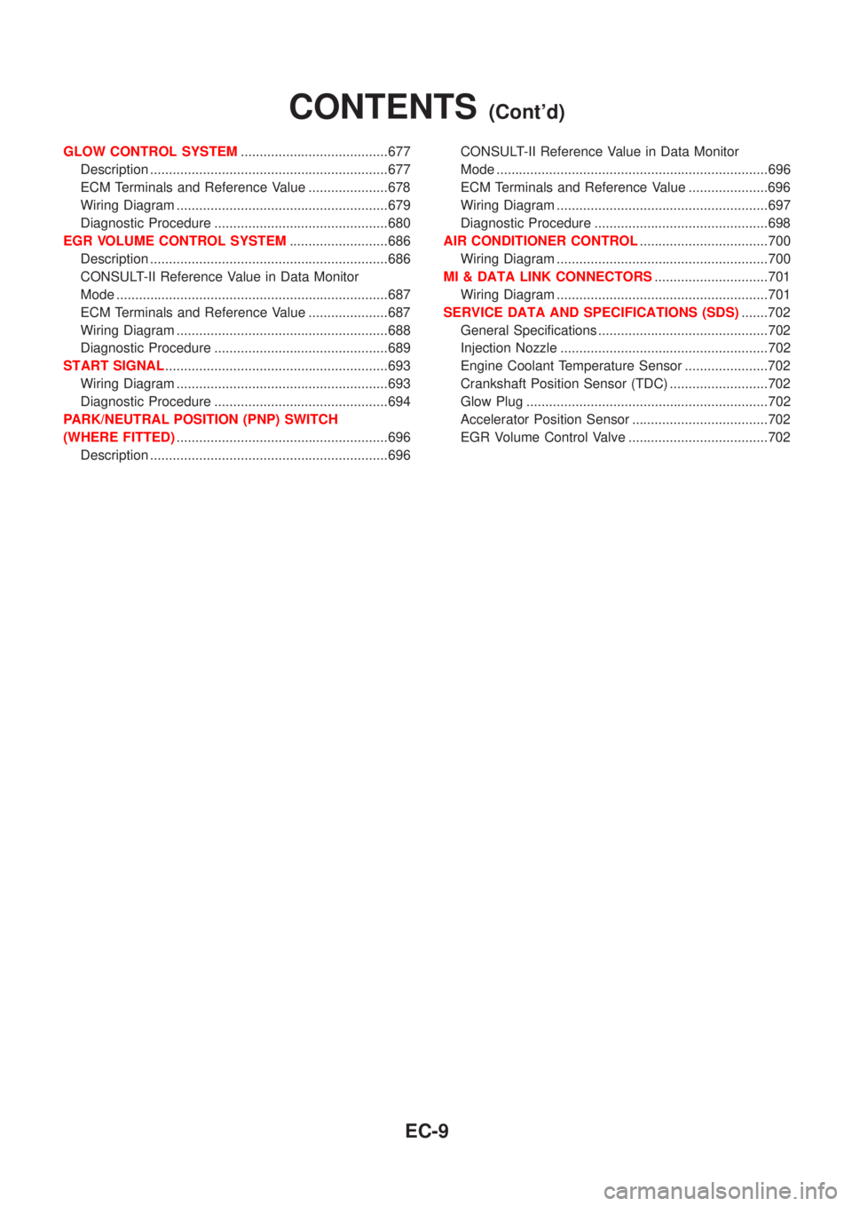
GLOW CONTROL SYSTEM.......................................677
Description ...............................................................677
ECM Terminals and Reference Value .....................678
Wiring Diagram ........................................................679
Diagnostic Procedure ..............................................680
EGR VOLUME CONTROL SYSTEM..........................686
Description ...............................................................686
CONSULT-II Reference Value in Data Monitor
Mode ........................................................................687
ECM Terminals and Reference Value .....................687
Wiring Diagram ........................................................688
Diagnostic Procedure ..............................................689
START SIGNAL...........................................................693
Wiring Diagram ........................................................693
Diagnostic Procedure ..............................................694
PARK/NEUTRAL POSITION (PNP) SWITCH
(WHERE FITTED)........................................................696
Description ...............................................................696CONSULT-II Reference Value in Data Monitor
Mode ........................................................................696
ECM Terminals and Reference Value .....................696
Wiring Diagram ........................................................697
Diagnostic Procedure ..............................................698
AIR CONDITIONER CONTROL..................................700
Wiring Diagram ........................................................700
MI & DATA LINK CONNECTORS..............................701
Wiring Diagram ........................................................701
SERVICE DATA AND SPECIFICATIONS (SDS).......702
General Specifications .............................................702
Injection Nozzle .......................................................702
Engine Coolant Temperature Sensor ......................702
Crankshaft Position Sensor (TDC) ..........................702
Glow Plug ................................................................702
Accelerator Position Sensor ....................................702
EGR Volume Control Valve .....................................702
CONTENTS(Cont'd)
EC-9
Page 324 of 2493

System ChartNJEC0013
Input (Sensor) ECM Function Output (Actuator)
+Camshaft position sensor (PHASE)
+Crankshaft position sensor (POS)
+Mass air flow sensor
+Engine coolant temperature sensor
+Heated oxygen sensor 1 (front)
+Ignition switch
+Throttle position sensor
+PNP switch
+Air conditioner switch
+Knock sensor
+EGR temperature sensor*1, *4
+Battery voltage
+Power steering oil pressure switch
+Vehicle speed sensor
+Intake air temperature sensor
+Heated oxygen sensor 2 (rear)*2
+TCM (Transmission Control Module)*3
+Closed throttle position switch
+Electrical load
+Refrigerant pressure sensorFuel injection & mixture ratio control Injectors
Electronic ignition system Power transistor
Idle air control system IACV-AAC valve
Intake valve timing controlIntake valve timing control sole-
noid valve
Fuel pump control Fuel pump relay
On board diagnostic systemMalfunction indicator
(On the instrument panel)
EGR control*4 EGR volume control valve*4
Heated oxygen sensor 1/2 heater (front/
rear) controlHeated oxygen sensor 1/2 heater
(front/rear)
EVAP canister purge flow controlEVAP canister purge volume con-
trol solenoid valve
Cooling fan control Cooling fan relay
Air conditioning cut control Air conditioner relay
*1: These sensors are not used to control the engine system. They are used only for the on board diagnosis.
*2: Under normal conditions, this sensor is not for engine control operation.
*3: The DTC related to A/T will be sent to ECM.
*4: If so equipped
ENGINE AND EMISSION CONTROL OVERALL SYSTEMQG
System Chart
EC-28
Page 325 of 2493

Multiport Fuel Injection (MFI) System
DESCRIPTIONNJEC0014Input/Output Signal ChartNJEC0014S01
Sensor Input Signal to ECMECM func-
tionActuator
Crankshaft position sensor (POS) Engine speed
Fuel injec-
tion & mix-
ture ratio
controlInjector Camshaft position sensor (PHASE) Engine speed and cylinder number
Mass air flow sensor Amount of intake air
Engine coolant temperature sensor Engine coolant temperature
Heated oxygen sensor 1 (front) Density of oxygen in exhaust gas
Throttle position sensorThrottle position
Throttle valve idle position
PNP switch Gear position
Vehicle speed sensor Vehicle speed
Ignition switch Start signal
Air conditioner switch Air conditioner operation
Knock sensor Engine knocking condition
Electrical load Electrical load signal
Battery Battery voltage
Power steering oil pressure switch Power steering operation
Heated oxygen sensor 2 (rear)* Density of oxygen in exhaust gas
* Under normal conditions, this sensor is not for engine control operation.
Basic Multiport Fuel Injection SystemNJEC0014S02The amount of fuel injected from the fuel injector is determined by the ECM. The ECM controls the length of
time the valve remains open (injection pulse duration). The amount of fuel injected is a program value in the
ECM memory. The program value is preset by engine operating conditions. These conditions are determined
by input signals (for engine speed and intake air) from both the camshaft position sensor and the mass air
flow sensor.
Various Fuel Injection Increase/Decrease CompensationNJEC0014S03In addition, the amount of fuel injected is compensated to improve engine performance under various oper-
ating conditions as listed below.
+During warm-up
+When starting the engine
+During acceleration
+Hot-engine operation
+When selector lever is changed from ªNº to ªDº (A/T models)
+High-load, high-speed operation
+During deceleration
+During high engine speed operation
+During high vehicle speed operation (M/T models)
+Extremely high engine coolant temperature
ENGINE AND EMISSION BASIC CONTROL SYSTEM DESCRIPTIONQG
Multiport Fuel Injection (MFI) System
EC-29
Page 326 of 2493

Mixture Ratio Feedback Control (Closed loop control)NJEC0014S04
SEF336WA
The mixture ratio feedback system provides the best air-fuel mixture ratio for driveability and emission con-
trol. The three way catalyst can then better reduce CO, HC and NOx emissions. This system uses a heated
oxygen sensor 1 (front) in the exhaust manifold to monitor if the engine operation is rich or lean. The ECM
adjusts the injection pulse width according to the sensor voltage signal. For more information about the heated
oxygen sensor 1 (front), refer to EC-176. This maintains the mixture ratio within the range of stoichiometric
(ideal air-fuel mixture).
This stage is referred to as the closed loop control condition.
Heated oxygen sensor 2 (rear) is located downstream of the three way catalyst. Even if the switching char-
acteristics of the heated oxygen sensor 1 (front) shift, the air-fuel ratio is controlled to stoichiometric by the
signal from the heated oxygen sensor 2 (rear).
Open Loop ControlNJEC0014S05The open loop system condition refers to when the ECM detects any of the following conditions. Feedback
control stops in order to maintain stabilized fuel combustion.
+Deceleration and acceleration
+High-load, high-speed operation
+Malfunction of heated oxygen sensor 1 (front) or its circuit
+Insufficient activation of heated oxygen sensor 1 (front) at low engine coolant temperature
+High engine coolant temperature
+During warm-up
+When starting the engine
Mixture Ratio Self-learning ControlNJEC0014S06The mixture ratio feedback control system monitors the mixture ratio signal transmitted from the heated oxy-
gen sensor 1 (front). This feedback signal is then sent to the ECM. The ECM controls the basic mixture ratio
as close to the theoretical mixture ratio as possible. However, the basic mixture ratio is not necessarily con-
trolled as originally designed. Both manufacturing differences (i.e., mass air flow sensor hot film) and charac-
teristic changes during operation (i.e., injector clogging) directly affect mixture ratio.
Accordingly, the difference between the basic and theoretical mixture ratios is monitored in this system. This
is then computed in terms of ªinjection pulse durationº to automatically compensate for the difference between
the two ratios.
ªFuel trimº refers to the feedback compensation value compared against the basic injection duration. Fuel trim
includes short term fuel trim and long term fuel trim.
ªShort term fuel trimº is the short-term fuel compensation used to maintain the mixture ratio at its theoretical
value. The signal from the heated oxygen sensor 1 (front) indicates whether the mixture ratio is RICH or LEAN
compared to the theoretical value. The signal then triggers a reduction in fuel volume if the mixture ratio is
rich, and an increase in fuel volume if it is lean.
ªLong term fuel trimº is overall fuel compensation carried out long-term to compensate for continual deviation
of the short term fuel trim from the central value. Such deviation will occur due to individual engine differences,
wear over time and changes in the usage environment.
ENGINE AND EMISSION BASIC CONTROL SYSTEM DESCRIPTIONQG
Multiport Fuel Injection (MFI) System (Cont'd)
EC-30