2001 NISSAN ALMERA N16 Ventilation
[x] Cancel search: VentilationPage 303 of 2493

YD
TROUBLE DIAGNOSIS - INDEX................................492
Alphabetical & P No. Index for DTC .......................492
PRECAUTIONS...........................................................494
Supplemental Restraint System (SRS)²AIR
BAG²and²SEAT BELT PRE-TENSIONER²...........494
Engine Fuel & Emission Control System ................495
Precautions ..............................................................496
Wiring Diagrams and Trouble Diagnosis .................497
PREPARATION...........................................................498
Special Service Tools ..............................................498
ENGINE AND EMISSION CONTROL OVERALL
SYSTEM.......................................................................499
Engine Control Component Parts Location .............499
Circuit Diagram ........................................................502
System Diagram ......................................................503
System Chart ...........................................................504
ENGINE AND EMISSION BASIC CONTROL
SYSTEM DESCRIPTION.............................................505
Fuel Injection Control System .................................505
Fuel Injection Timing Control System......................506
Air Conditioning Cut Control ....................................507
Fuel Cut Control (at no load & high engine
speed) ......................................................................507
Crankcase Ventilation System .................................508
BASIC SERVICE PROCEDURE.................................509
Injection Tube and Injection Nozzle ........................509
Electronic Control Fuel Injection Pump ...................513
Fuel Filter .................................................................520
ON BOARD DIAGNOSTIC SYSTEM
DESCRIPTION.............................................................522
DTC and MI Detection Logic ...................................522
Diagnostic Trouble Code (DTC) ..............................522
Malfunction Indicator (MI) ........................................523
CONSULT-II .............................................................527
TROUBLE DIAGNOSIS - INTRODUCTION................532
Introduction ..............................................................532
Work Flow ................................................................534
TROUBLE DIAGNOSIS - BASIC INSPECTION.........536
Basic Inspection.......................................................536
TROUBLE DIAGNOSIS - GENERAL
DESCRIPTION.............................................................541
Symptom Matrix Chart .............................................541
CONSULT-II Reference Value in Data Monitor
Mode ........................................................................551
Major Sensor Reference Graph in Data Monitor
Mode ........................................................................553
ECM Terminals and Reference Value .....................554
TROUBLE DIAGNOSIS FOR INTERMITTENT
INCIDENT.....................................................................559
Description ...............................................................559
Diagnostic Procedure ..............................................559TROUBLE DIAGNOSIS FOR POWER SUPPLY........560
Main Power Supply and Ground Circuit ..................560
DTC P0100 MASS AIR FLOW SEN...........................566
Component Description ...........................................566
CONSULT-II Reference Value in Data Monitor
Mode ........................................................................566
ECM Terminals and Reference Value .....................566
On Board Diagnosis Logic.......................................566
DTC Confirmation Procedure ..................................566
Wiring Diagram ........................................................568
Diagnostic Procedure ..............................................569
DTC P0115 COOLANT TEMP SEN............................572
Description ...............................................................572
On Board Diagnosis Logic.......................................572
DTC Confirmation Procedure ..................................572
Wiring Diagram ........................................................574
Diagnostic Procedure ..............................................575
DTC P0120 ACCEL POS SENSOR............................577
Description ...............................................................577
CONSULT-II Reference Value in Data Monitor
Mode ........................................................................577
ECM Terminals and Reference Value .....................577
On Board Diagnosis Logic.......................................578
DTC Confirmation Procedure ..................................578
Wiring Diagram ........................................................579
Diagnostic Procedure ..............................................580
DTC P0335 CRANK POS SEN (TDC)........................587
Description ...............................................................587
CONSULT-II Reference Value in Data Monitor
Mode ........................................................................587
ECM Terminals and Reference Value .....................587
On Board Diagnosis Logic.......................................587
DTC Confirmation Procedure ..................................588
Wiring Diagram ........................................................589
Diagnostic Procedure ..............................................590
DTC P0500 VEHICLE SPEED SEN............................593
Description ...............................................................593
ECM Terminals and Reference Value .....................593
On Board Diagnosis Logic.......................................593
Overall Function Check ...........................................593
Wiring Diagram ........................................................595
Diagnostic Procedure ..............................................596
DTC P0571 BRAKE SW..............................................597
Description ...............................................................597
ECM Terminals and Reference Value .....................597
On Board Diagnosis Logic.......................................597
DTC Confirmation Procedure ..................................597
Wiring Diagram ........................................................599
Diagnostic Procedure ..............................................600
DTC P1107 ECM 10....................................................604
Description ...............................................................604
On Board Diagnosis Logic.......................................604
CONTENTS(Cont'd)
EC-7
Page 333 of 2493
Positive Crankcase Ventilation
DESCRIPTIONNJEC0022
SEF921W
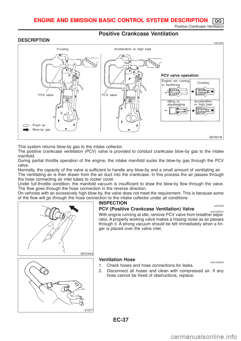
This system returns blow-by gas to the intake collector.
The positive crankcase ventilation (PCV) valve is provided to conduct crankcase blow-by gas to the intake
manifold.
During partial throttle operation of the engine, the intake manifold sucks the blow-by gas through the PCV
valve.
Normally, the capacity of the valve is sufficient to handle any blow-by and a small amount of ventilating air.
The ventilating air is then drawn from the air duct into the crankcase. In this process the air passes through
the hose connecting air inlet tubes to rocker cover.
Under full-throttle condition, the manifold vacuum is insufficient to draw the blow-by flow through the valve.
The flow goes through the hose connection in the reverse direction.
On vehicles with an excessively high blow-by, the valve does not meet the requirement. This is because some
of the flow will go through the hose connection to the intake collector under all conditions.
SEF244Q
INSPECTIONNJEC0023PCV (Positive Crankcase Ventilation) ValveNJEC0023S01With engine running at idle, remove PCV valve from breather sepa-
rator. A properly working valve makes a hissing noise as air passes
through it. A strong vacuum should be felt immediately when a fin-
ger is placed over the valve inlet.
ET277
Ventilation HoseNJEC0023S021. Check hoses and hose connections for leaks.
2. Disconnect all hoses and clean with compressed air. If any
hose cannot be freed of obstructions, replace.
ENGINE AND EMISSION BASIC CONTROL SYSTEM DESCRIPTIONQG
Positive Crankcase Ventilation
EC-37
Page 497 of 2493

8 CHECK HEATED OXYGEN SENSOR 1 (FRONT)
Refer to ªComponent Inspectionº, EC-201.
OK or NG
OK©GO TO 9.
NG©Replace heated oxygen sensor 1 (front).
9 CHECK MASS AIR FLOW SENSOR
Refer to ªComponent Inspectionº, EC-157.
OK or NG
OK©GO TO 10.
NG©Replace mass air flow sensor.
10 CHECK PCV VALVE
Refer to ªPositive Crankcase Ventilationº, EC-37.
OK or NG
OK©GO TO 11.
NG©Repair or replace PCV valve.
11 CHECK INTERMITTENT INCIDENT
Perform ªTROUBLE DIAGNOSIS FOR INTERMITTENT INCIDENTº, EC-144.
©INSPECTION END
SEF646Y
SEF647Y
Component InspectionNJEC0127HEATED OXYGEN SENSOR 1 (FRONT)NJEC0127S02With CONSULT-II
1) Start engine and warm it up to normal operating temperature.
2) Select ªMANU TRIGº in ªDATA MONITORº mode, and select
ªHO2S1 (B1)º and ªHO2S1 MNTR (B1)º.
3) Hold engine speed at 2,000 rpm under no load during the fol-
lowing steps.
4) Touch ªRECORDº on CONSULT-II screen.
5) Check the following.
+ªHO2S1 MNTR (B1)º in ªDATA MONITORº mode changes from
ªRICHº to ªLEANº to ªRICHº five times in 10 seconds.
5 times (cycles) are counted as shown below:
R = ªHO2S1 MNTR (B1)º, ªRICHº
L = ªHO2S1 MNTR (B1)º, ªLEANº
+ªHO2S1 (B1)º voltage goes above 0.6V at least once.
+ªHO2S1 (B1)º voltage goes below 0.3V at least once.
+ªHO2S1 (B1)º voltage never exceeds 1.0V.
CAUTION:
+Discard any heated oxygen sensor which has been
dropped from a height of more than 0.5 m (19.7 in) onto a
hard surface such as a concrete floor; use a new one.
DTC P0133 HEATED OXYGEN SENSOR 1 (FRONT)
(RESPONSE MONITORING)
QG
Diagnostic Procedure (Cont'd)
EC-201
Page 804 of 2493

SEF440Z
Crankcase Ventilation System
DESCRIPTIONNJEC0616In this system, blow-by gas is sucked into the air duct after oil
separation by oil separator in the rocker cover.
SEC692
INSPECTIONNJEC0617Ventilation HoseNJEC0617S011. Check hoses and hose connections for leaks.
2. Disconnect all hoses and clean with compressed air. If any
hose cannot be freed of obstructions, replace.
ENGINE AND EMISSION BASIC CONTROL SYSTEM DESCRIPTIONYD
Crankcase Ventilation System
EC-508
Page 1973 of 2493
HEATER &
AIR CONDITIONER
SECTION
HA
CONTENTS
PRECAUTIONS...............................................................2
Supplemental Restraint System (SRS)²AIR
BAG²and²SEAT BELT PRE-TENSIONER²...............2
Precautions for Working with HFC-134a (R-134a) .....2
General Refrigerant Precautions .................................2
Precautions for Refrigerant Connection ......................3
Precautions for Servicing Compressor ........................5
Precautions for Service Equipment .............................6
Wiring Diagrams and Trouble Diagnosis .....................8
PREPARATION...............................................................9
Special Service Tools ..................................................9
HFC-134a (R-134a) Service Tools and
Equipment .................................................................. 11
DESCRIPTION...............................................................13
Refrigeration System .................................................13
CSV613 Variable Displacement Compressor............14
Component Layout ....................................................18
Control Operation ......................................................19
Discharge Air Flow.....................................................20
System Description ....................................................21
TROUBLE DIAGNOSES................................................22
Component Location..................................................22
Wiring Diagram - Heater............................................24
Circuit Diagram - Air Conditioner...............................26
Wiring Diagram - A/C, M - .........................................27
How to Perform Trouble Diagnoses for Quick
and Accurate Repair ..................................................39
Operational Check .....................................................40
Intake Door ................................................................42
Mode Door .................................................................46Air Mix Door ...............................................................48
Max Hot Door (For Scandinavia and Cold Spec
Models) ......................................................................50
Blower Motor..............................................................54
Magnet Clutch............................................................61
Insufficient Cooling ....................................................74
Insufficient Heating ....................................................82
Noise ..........................................................................83
SERVICE PROCEDURE................................................84
HFC-134a (R-134a) Service Procedure ....................84
Maintenance of Lubricant Quantity in
Compressor ...............................................................86
Compressor ...............................................................89
Compressor Clutch - CSV613 (CALSONIC
make) .........................................................................90
Heater & Cooling Unit (Heater Core) ........................94
A/C Evaporator ..........................................................94
Blower Unit ................................................................95
Refrigerant Lines .......................................................97
Belt ...........................................................................101
Idle Air Control Valve (IACV) - Auxiliary Air
Control (AAC) Valve ................................................102
Ventilation Air Filter ..................................................102
SERVICE DATA AND SPECIFICATIONS (SDS).......103
Compressor .............................................................103
Lubricant ..................................................................103
Refrigerant ...............................................................103
Engine Idling Speed (When A/C is On)...................103
Belt Tension .............................................................103
Page 2074 of 2493
Idle Air Control Valve (IACV) Ð Auxiliary Air
Control (AAC) Valve
INSPECTIONNJHA0199+Refer to EC-313 (QG), ªSystem Descriptionº.
RHA680H
Ventilation Air Filter
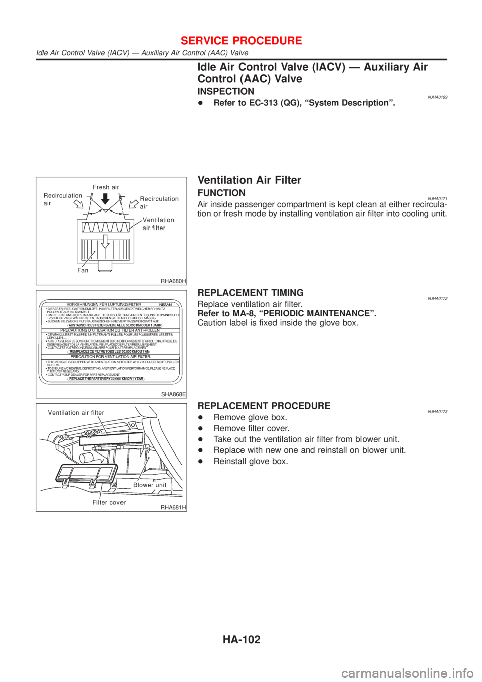
FUNCTIONNJHA0171Air inside passenger compartment is kept clean at either recircula-
tion or fresh mode by installing ventilation air filter into cooling unit.
SHA868E
REPLACEMENT TIMINGNJHA0172Replace ventilation air filter.
Refer to MA-8, ªPERIODIC MAINTENANCEº.
Caution label is fixed inside the glove box.
RHA681H
REPLACEMENT PROCEDURENJHA0173+Remove glove box.
+Remove filter cover.
+Take out the ventilation air filter from blower unit.
+Replace with new one and reinstall on blower unit.
+Reinstall glove box.
SERVICE PROCEDURE
Idle Air Control Valve (IACV) Ð Auxiliary Air Control (AAC) Valve
HA-102
Page 2483 of 2493
CONSULT for ABS .................................... BR-58
CONSULT for engine ........................ EC-81, 527
COOL/F - Wiring diagram ............... EC-337, 618
Camshaft inspection ......................... EM-36, 122
Camshaft position sensor (CMPS) ......... EC-278
Camshaft position sensor (PHASE) ........ EC-278
Canister - See EVAP canister ................... EC-33
Charging system ....................................... SC-24
Cigarette lighter ....................................... EL-136
Circuit breaker ........................................... EL-22
Closed throttle position switch ....... EC-321, 426
Clutch cover .............................................. CL-22
Clutch disc ................................................. CL-22
Clutch master cylinder ............................... CL-11
Clutch operating cylinder ........................... CL-14
Clutch pedal .............................................. CL-10
Clutch release bearing ........................ CL-17, 20
Clutch release mechanism .................. CL-17, 20
Clutch withdrawal lever ....................... CL-17, 20
Coil spring (front) ........................................ SU-9
Coil spring (rear) ....................................... SU-21
Collision diagnosis .................................... RS-71
Combination lamp, rear, removal and
installation .............................................. BT-47
Combination meter removal and instal-
lation - See Instrument panel ................ BT-25
Combination meter .................................... EL-89
Combination switch ................................... EL-37
Compression pressure ............................. EM-82
Compressor clutch removal and
installation .............................................. HA-89
Compressor precaution ............................... HA-5
Compressor special service tool ................. HA-9
Connecting rod bearing clearance ... EM-58, 150
Connecting rod bushing clearance ... EM-59, 152
Connecting rod ................................. EM-55, 145
Console box - See Instrument panel ......... BT-25
Control lever (M/T) .................................... MT-29
Control valve (A/T) ................................... AT-375
Converter housing installation ................. AT-347
Coolant mixture ratio ................................ MA-22
Cooling circuit (engine) ....................... LC-12, 36
Cooling fan control system .................. LC-17, 42
Cooling fan control .......................... EC-334, 618
Cooling fan motor ................................... EC-346
Cooling fan relay ..................................... EC-345
Coupling sleeve (M/T) .................. MT-31, 55, 93
Crankcase emission control system -
See Positive crankcase ventilation ...... EC-37,
508
Crankcase ventilation system - See
Positive crankcase ventilation ....... EC-37, 508
Crankshaft position sensor (OBD) .. EC-272, 394
Crankshaft position sensor (POS) .. EC-272, 394
Crankshaft position sensor (TDC) .......... EC-587
Crankshaft ........................................ EM-57, 148
Cylinder block ................................... EM-52, 139
Cylinder head .................................... EM-33, 118D
DEF - Wiring diagram .............................. EL-140
DTC work support ..................................... EC-90
Data link connector for Consult ........ EC-38, 527
Daytime light system ................................. EL-44
Detonation sensor - See Knock
sensor .................................................. EC-268
Diagnosis sensor unit ............................... RS-26
Diagnostic trouble code (DTC) for
OBD system .................... EC-10, 70, 492, 522
Diagnostic trouble code (DTC) inspec-
tion priority chart .................................. EC-122
Differential gear (FF A/T) ......................... AT-424
Differential gear (FF M/T) ...... MT-31, 43, 55, 93,
107
Dimensions ................................................. GI-43
Dome light - See Interior lamp .................. EL-76
Door glass ................................................. BT-17
Door lock ................................................... BT-21
Door mirror ................................................ BT-72
Door trim .................................................... BT-39
Door, front .................................................. BT-16
Door, rear ................................................... BT-16
Drive plate runout ..................................... EM-60
Drive shaft (front) ...................................... AX-10
Dropping resistor (A/T) .................... AT-180, 243
Dual pressure switch ................................ HA-13
E
ECCS-D control module ........ EC-554, 604, 664,
666, 670, 672
ECM input/output signal ................. EC-132, 554
ECTS - Wiring diagram ................... EC-165, 572
EGR control valve ................................... EC-359
EGR temperature sensor ........................ EC-347
EGR volume control valve ...................... EC-686
EGR/TS - Wiring diagram ....................... EC-350
EGRC1 - Wiring diagram ....... EC-289, 357, 403,
688
EVAP canister purge volume control
solenoid valve ........................................ EC-34
EVAP canister purge volume control
valve ............................................ EC-304, 411
EVAP canister ........................................... EC-34
Electric sunroof ........................................ EL-165
Electrical diagnoses ................................... GI-21
Electrical ignition system .......................... EC-31
Electrical load signal circuit ..................... EC-480
Electrical unit ........................................... EL-371
Electrical units location ............................ EL-319
Electronic fuel injection pump ........ EC-513, 606,
612, 634, 640, 646, 652, 658, 674
Engine compartment ................................. BT-75
Engine control circuit diagram .......... EC-25, 502
Engine control component parts
location .......................................... EC-21, 499
ALPHABETICAL INDEX
IDX-3
Page 2486 of 2493
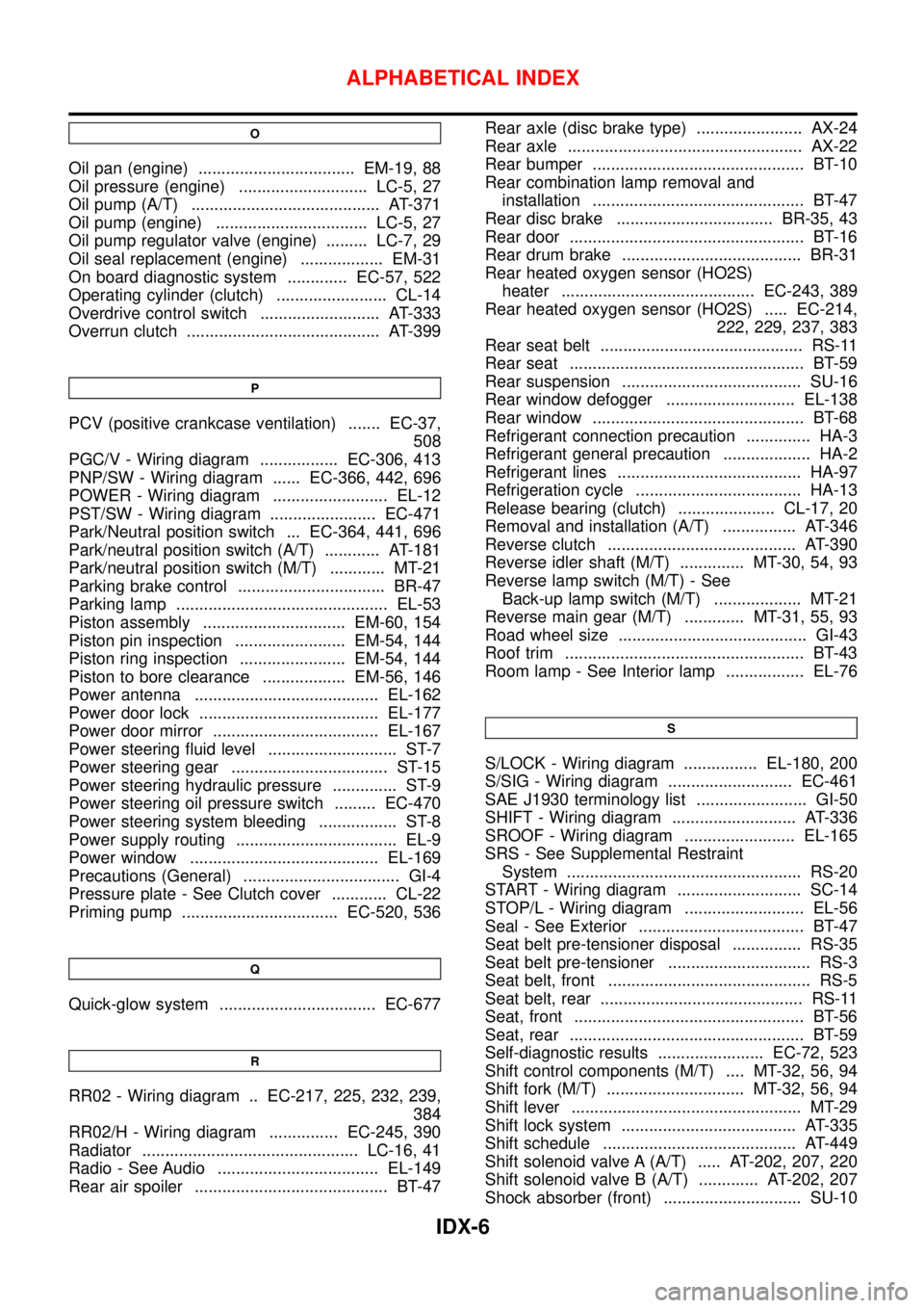
O
Oil pan (engine) .................................. EM-19, 88
Oil pressure (engine) ............................ LC-5, 27
Oil pump (A/T) ......................................... AT-371
Oil pump (engine) ................................. LC-5, 27
Oil pump regulator valve (engine) ......... LC-7, 29
Oil seal replacement (engine) .................. EM-31
On board diagnostic system ............. EC-57, 522
Operating cylinder (clutch) ........................ CL-14
Overdrive control switch .......................... AT-333
Overrun clutch .......................................... AT-399
P
PCV (positive crankcase ventilation) ....... EC-37,
508
PGC/V - Wiring diagram ................. EC-306, 413
PNP/SW - Wiring diagram ...... EC-366, 442, 696
POWER - Wiring diagram ......................... EL-12
PST/SW - Wiring diagram ....................... EC-471
Park/Neutral position switch ... EC-364, 441, 696
Park/neutral position switch (A/T) ............ AT-181
Park/neutral position switch (M/T) ............ MT-21
Parking brake control ................................ BR-47
Parking lamp .............................................. EL-53
Piston assembly ............................... EM-60, 154
Piston pin inspection ........................ EM-54, 144
Piston ring inspection ....................... EM-54, 144
Piston to bore clearance .................. EM-56, 146
Power antenna ........................................ EL-162
Power door lock ....................................... EL-177
Power door mirror .................................... EL-167
Power steering fluid level ............................ ST-7
Power steering gear .................................. ST-15
Power steering hydraulic pressure .............. ST-9
Power steering oil pressure switch ......... EC-470
Power steering system bleeding ................. ST-8
Power supply routing ................................... EL-9
Power window ......................................... EL-169
Precautions (General) .................................. GI-4
Pressure plate - See Clutch cover ............ CL-22
Priming pump .................................. EC-520, 536
Q
Quick-glow system .................................. EC-677
R
RR02 - Wiring diagram .. EC-217, 225, 232, 239,
384
RR02/H - Wiring diagram ............... EC-245, 390
Radiator ............................................... LC-16, 41
Radio - See Audio ................................... EL-149
Rear air spoiler .......................................... BT-47Rear axle (disc brake type) ....................... AX-24
Rear axle ................................................... AX-22
Rear bumper .............................................. BT-10
Rear combination lamp removal and
installation .............................................. BT-47
Rear disc brake .................................. BR-35, 43
Rear door ................................................... BT-16
Rear drum brake ....................................... BR-31
Rear heated oxygen sensor (HO2S)
heater .......................................... EC-243, 389
Rear heated oxygen sensor (HO2S) ..... EC-214,
222, 229, 237, 383
Rear seat belt ............................................ RS-11
Rear seat ................................................... BT-59
Rear suspension ....................................... SU-16
Rear window defogger ............................ EL-138
Rear window .............................................. BT-68
Refrigerant connection precaution .............. HA-3
Refrigerant general precaution ................... HA-2
Refrigerant lines ........................................ HA-97
Refrigeration cycle .................................... HA-13
Release bearing (clutch) ..................... CL-17, 20
Removal and installation (A/T) ................ AT-346
Reverse clutch ......................................... AT-390
Reverse idler shaft (M/T) .............. MT-30, 54, 93
Reverse lamp switch (M/T) - See
Back-up lamp switch (M/T) ................... MT-21
Reverse main gear (M/T) ............. MT-31, 55, 93
Road wheel size ......................................... GI-43
Roof trim .................................................... BT-43
Room lamp - See Interior lamp ................. EL-76
S
S/LOCK - Wiring diagram ................ EL-180, 200
S/SIG - Wiring diagram ........................... EC-461
SAE J1930 terminology list ........................ GI-50
SHIFT - Wiring diagram ........................... AT-336
SROOF - Wiring diagram ........................ EL-165
SRS - See Supplemental Restraint
System ................................................... RS-20
START - Wiring diagram ........................... SC-14
STOP/L - Wiring diagram .......................... EL-56
Seal - See Exterior .................................... BT-47
Seat belt pre-tensioner disposal ............... RS-35
Seat belt pre-tensioner ............................... RS-3
Seat belt, front ............................................ RS-5
Seat belt, rear ............................................ RS-11
Seat, front .................................................. BT-56
Seat, rear ................................................... BT-59
Self-diagnostic results ....................... EC-72, 523
Shift control components (M/T) .... MT-32, 56, 94
Shift fork (M/T) .............................. MT-32, 56, 94
Shift lever .................................................. MT-29
Shift lock system ...................................... AT-335
Shift schedule .......................................... AT-449
Shift solenoid valve A (A/T) ..... AT-202, 207, 220
Shift solenoid valve B (A/T) ............. AT-202, 207
Shock absorber (front) .............................. SU-10
ALPHABETICAL INDEX
IDX-6