2001 NISSAN ALMERA N16 Mass air flow sensor
[x] Cancel search: Mass air flow sensorPage 867 of 2493

6 CHECK MASS AIR FLOW SENSOR
1. Reconnect harness connectors disconnected.
2. Start engine and warm it up to normal operating temperature.
3. Check voltage between ECM terminal 224 (Mass air flow sensor signal) and ground.
SEF441Z
4. If the voltage is out of specification, disconnect MAFS harness connector and connect it again.
Then repeat above check.
OK or NG
OK©GO TO 7.
NG©Replace mass air flow sensor.
7 CHECK INTERMITTENT INCIDENT
Refer to ªTROUBLE DIAGNOSIS FOR INTERMITTENT INCIDENTº, EC-559.
©INSPECTION END
DTC P0100 MASS AIR FLOW SENYD
Diagnostic Procedure (Cont'd)
EC-571
Page 982 of 2493

DescriptionNJEC0764SYSTEM DESCRIPTIONNJEC0764S01
Sensor Input Signal to ECM ECM Function Actuator
Electronic controlled fuel injection pump Fuel injection signal
EGR volume con-
trolEGR volume control
valve Crankshaft position sensor (TDC) Engine speed
Vehicle speed sensor Vehicle speed
Engine coolant temperature sensor Engine coolant temperature
Ignition switch Start signal
Accelerator position sensor Accelerator position
Mass air flow sensor Amount of intake air
Air conditioner switch Air conditioner operation
Electrical load Electrical load signal
This system controls flow rate of EGR led from exhaust manifold
to intake manifold. The opening of the EGR by-pass passage in the
EGR volume control valve changes to control the flow rate. A
built-in step motor moves the valve in steps corresponding to the
ECM output pulses. The opening of the valve varies for optimum
engine control. The optimum value stored in the ECM is determined
by considering various engine conditions.
The EGR volume control valve remains close under the following
conditions.
+Engine stopped
+Engine starting
+Low engine coolant temperature
+Excessively high engine coolant temperature
+High engine speed
+Wide open throttle
SEF908Y
SEF411Y
COMPONENT DESCRIPTIONNJEC0764S02EGR Volume Control ValveNJEC0764S0201The EGR volume control valve uses a step motor to control the flow
rate of EGR from exhaust manifold. This motor has four winding
phases. It operates according to the output pulse signal of the
ECM. Two windings are turned ON and OFF in sequence. Each
time an ON pulse is issued, the valve opens or closes, changing
the flow rate. When no change in the flow rate is needed, the ECM
does not issue the pulse signal. A certain voltage signal is issued
so that the valve remains at that particular opening.
EGR VOLUME CONTROL SYSTEMYD
Description
EC-686
Page 1073 of 2493

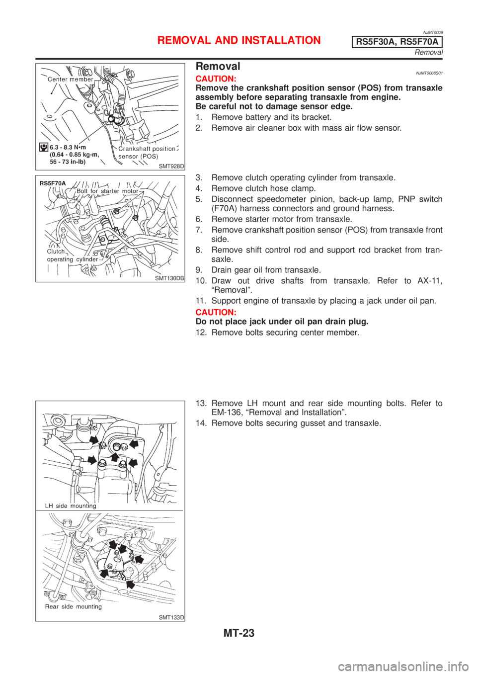
NJMT0008
SMT928D
RemovalNJMT0008S01CAUTION:
Remove the crankshaft position sensor (POS) from transaxle
assembly before separating transaxle from engine.
Be careful not to damage sensor edge.
1. Remove battery and its bracket.
2. Remove air cleaner box with mass air flow sensor.
SMT130DB
3. Remove clutch operating cylinder from transaxle.
4. Remove clutch hose clamp.
5. Disconnect speedometer pinion, back-up lamp, PNP switch
(F70A) harness connectors and ground harness.
6. Remove starter motor from transaxle.
7. Remove crankshaft position sensor (POS) from transaxle front
side.
8. Remove shift control rod and support rod bracket from tran-
saxle.
9. Drain gear oil from transaxle.
10. Draw out drive shafts from transaxle. Refer to AX-11,
ªRemovalº.
11. Support engine of transaxle by placing a jack under oil pan.
CAUTION:
Do not place jack under oil pan drain plug.
12. Remove bolts securing center member.
SMT133D
13. Remove LH mount and rear side mounting bolts. Refer to
EM-136, ªRemoval and Installationº.
14. Remove bolts securing gusset and transaxle.
REMOVAL AND INSTALLATIONRS5F30A, RS5F70A
Removal
MT-23
Page 1076 of 2493

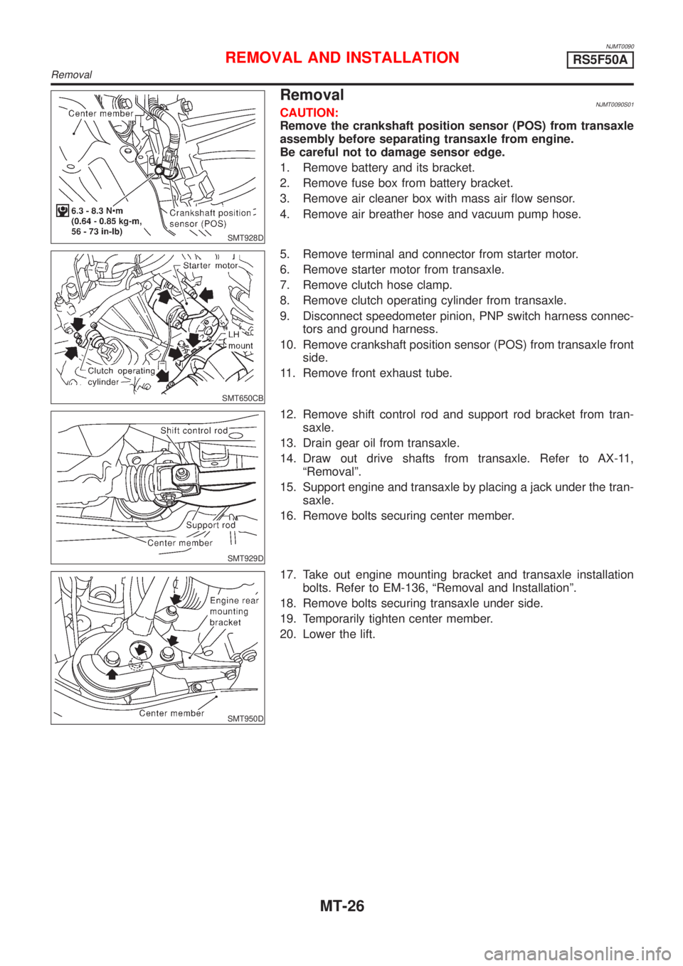
NJMT0090
SMT928D
RemovalNJMT0090S01CAUTION:
Remove the crankshaft position sensor (POS) from transaxle
assembly before separating transaxle from engine.
Be careful not to damage sensor edge.
1. Remove battery and its bracket.
2. Remove fuse box from battery bracket.
3. Remove air cleaner box with mass air flow sensor.
4. Remove air breather hose and vacuum pump hose.
SMT650CB
5. Remove terminal and connector from starter motor.
6. Remove starter motor from transaxle.
7. Remove clutch hose clamp.
8. Remove clutch operating cylinder from transaxle.
9. Disconnect speedometer pinion, PNP switch harness connec-
tors and ground harness.
10. Remove crankshaft position sensor (POS) from transaxle front
side.
11. Remove front exhaust tube.
SMT929D
12. Remove shift control rod and support rod bracket from tran-
saxle.
13. Drain gear oil from transaxle.
14. Draw out drive shafts from transaxle. Refer to AX-11,
ªRemovalº.
15. Support engine and transaxle by placing a jack under the tran-
saxle.
16. Remove bolts securing center member.
SMT950D
17. Take out engine mounting bracket and transaxle installation
bolts. Refer to EM-136, ªRemoval and Installationº.
18. Remove bolts securing transaxle under side.
19. Temporarily tighten center member.
20. Lower the lift.
REMOVAL AND INSTALLATIONRS5F50A
Removal
MT-26
Page 2479 of 2493

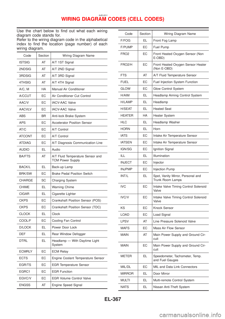
NJEL0311
Use the chart below to find out what each wiring
diagram code stands for.
Refer to the wiring diagram code in the alphabetical
index to find the location (page number) of each
wiring diagram.
Code Section Wiring Diagram Name
ISTSIG AT A/T 1ST Signal
2NDSIG AT A/T 2ND Signal
3RDSIG AT A/T 3RD Signal
4THSIG AT A/T 4TH Signal
A/C, M HA Manual Air Conditioner
A/CCUT EC Air Conditioner Cut Control
AAC/V EC IACV-AAC Valve
AACVLV EC IACV-AAC Valve
ABS BR Anti-lock Brake System
APS EC Accelerator Position Sensor
AT/C EC A/T Control
ATCONT EC A/T Control
ATDIAG EC A/T Diagnosis Communication Line
AUDIO EL Audio
BA/FTS AT A/T Fluid Temperature Sensor and
TCM Power Supply
BACK/L EL Back-up Lamp
BRK/SW EC Brake Pedal Position Switch
CHARGE SC Charging System
CHIME EL Warning Chime
CIGAR EL Cigarette Lighter
CKPS EC Crankshaft Position Sensor (POS)
CKPS EC Crankshaft Position Sensor (TDC)
CLOCK EL Clock
COOL/F EC Cooling Fan Control
D/LOCK EL Power Door Lock
DEF EL Rear Window Defogger
DTRL EL Headlamp Ð With Daytime Light
System
ECMRLY EC ECM Relay
ECTS EC Engine Coolant Temperature Sensor
EGR/TS EC EGR Temperature Sensor
EGRC1 EC EGR Function
EGVC/V EC EGR Volume Control Valve
ENGSS AT Engine Speed Signal
Code Section Wiring Diagram Name
F/FOG EL Front Fog Lamp
F/PUMP EC Fuel Pump
FRO2 EC Front Heated Oxygen Sensor (Non
E-OBD)
FRO2/H EC Front Heated Oxygen Sensor Heater
(Non E-OBD)
FTS AT A/T Fluid Temperature Sensor
FUEL EC Fuel Injection System Function
GLOW EC Glow Control System
H/AIM EL Headlamp Aiming Control System
H/LAMP EL Headlamp
H/SEAT EL Heated Seat
HEATER HA Heater System
HLC EL Headlamp Washer
HORN EL Horn
IATS EC Intake Air Temperature Sensor
IATSEN EC Intake Air Temperature Sensor
IGN/SG EC Ignition Signal
ILL EL Illumination
INJECT EC Injector
INJPMP EC Injection Pump
INT/L EL Spot, Vanity Mirror, Personal and
Trunk Room Lamps
IVC EC Intake Valve Timing Control Solenoid
Valve
IVC/V EC Intake Valve Timing Control Solenoid
Valve
KS EC Knock Sensor
LOAD EC Load Signal
LPSV AT Line Pressure Solenoid Valve
MAFS EC Mass Air Flow Sensor
MAIN AT Main Power Supply and Ground Cir-
cuit
MAIN EC Main Power Supply and Ground Cir-
cuit
METER EL Speedometer, Tachometer, Temp.
and Fuel Gauges
MIL/DL EC MIL and Data Link Connectors
MIRROR EL Door Mirror
MULTI EL Multi-remote Control System
NATS EL Nissan Anti-Theft System
WIRING DIAGRAM CODES (CELL CODES)
EL-367
Page 2482 of 2493

A
A/C HFC134a (R134a) system precaution . HA-2
A/C HFC134a (R134a) system service
procedure .............................................. HA-84
A/C HFC134a (R134a) system service
tools ....................................................... HA-11
A/C HFC134a system service equip-
ment precaution ....................................... HA-6
A/C air flow ............................................... HA-20
A/C component layout .............................. HA-18
A/C compressor clutch removal and
installation .............................................. HA-89
A/C compressor precaution ........................ HA-5
A/C compressor special service tool .......... HA-9
A/C control linkage adjustment
(manual A/C) ......................................... HA-47
A/C control operation (manual A/C) .......... HA-19
A/C diagnostic work flow
(manual A/C) ......................................... HA-39
A/C harness layout (manual A/C) ............. HA-22
A/C lubricant (R134a) ............................... HA-86
A/C operational check ............................... HA-40
A/C performance chart .............................. HA-77
A/C performance test diagnoses .............. HA-75
A/C relay ................................................... HA-72
A/C service data specification ................ HA-103
A/C switch ................................................. HA-73
A/C, M - Wiring diagram ........................... HA-27
A/CCUT - Wiring diagram ....................... EC-700
A/T - Wiring diagram - AT - 1ST .............. AT-205
A/T - Wiring diagram - AT - 2ND ............. AT-212
A/T - Wiring diagram - AT - 3RD ............. AT-218
A/T - Wiring diagram - AT - 4TH .............. AT-225
A/T - Wiring diagram - AT - BA/FTS ....... AT-165,
273
A/T - Wiring diagram - AT - ENG SS ...... AT-171,
199
A/T - Wiring diagram - AT - FTS .............. AT-189
A/T - Wiring diagram - AT - LPSV ... AT-176, 239
A/T - Wiring diagram - AT - MAIN ........... AT-121
A/T - Wiring diagram - AT -
OVRCSV ...................................... AT-153, 267
A/T - Wiring diagram - AT - PNP/SW ...... AT-183
A/T - Wiring diagram - AT - SSV/A .. AT-142, 246
A/T - Wiring diagram - AT - SSV/B .. AT-148, 252
A/T - Wiring diagram - AT - TCV ..... AT-159, 233
A/T - Wiring diagram - AT - TPS ..... AT-134, 259
A/T - Wiring diagram - AT - VSS/AT ....... AT-126,
195
A/T - Wiring diagram - AT -
VSSMTR ...................................... AT-130, 280
A/T control ............................................... EC-437
A/T diagnosis communication line .......... EC-361
A/T fluid temperature sensor ................... AT-192
A/T shift lock system - Wiring
diagram ................................................ AT-336
A/T shift lock system ................................ AT-335
A/T trouble diagnoses .......................... AT-67, 72AAC/V - Wiring diagram ................. EC-315, 420
ABS (anti-lock brake system) ................... BR-49
ABS - Wiring diagram ............................... BR-54
ABS sensor rotor ....................................... AX-24
APS - Wiring diagram ............................. EC-577
ATDIAG - Wiring diagram ............... EC-362, 438
Accelerator control system .................... FE-3, 15
Accelerator position sensor .................... EC-577
Air bag disposal ........................................ RS-35
Air bag precautions ...................................... GI-3
Air bag ....................................................... RS-20
Air bleeding (hydraulic clutch) ................... CL-10
Air bleeding for brake system ..................... BR-8
Air conditioner cut control ................. EC-32, 507
Air flow meter - See Mass air flow
sensor .......................................... EC-152, 566
Air mix door control linkage
adjustment ............................................. HA-49
Air spoiler, rear .......................................... BT-47
Alternator ................................................... SC-27
Angular tightening application .............. EM-4, 76
Antenna - See Power antenna ................ EL-162
Anti-lock brake system - Wiring
diagram .................................................. BR-54
Audio and A/C control removal and
installation - See Instrument panel ........ BT-25
Audio ........................................................ EL-149
Automatic transaxle number ...................... GI-41
Auxiliary air control (AAC) valve ..... EC-313, 418
B
Back-up lamp switch (M/T) ....................... MT-21
Back-up lamp ............................................. EL-58
Ball joint (front) .......................................... SU-13
Basic inspection ................................ EC-98, 536
Battery ......................................................... SC-3
Baulk ring (M/T) ............................ MT-31, 55, 93
Blower motor ............................................. HA-60
Blower resistor .......................................... HA-60
Board-on lift ................................................ GI-44
Body alignment .......................................... BT-74
Brake booster ............................................ BR-20
Brake fluid change ...................................... BR-7
Brake fluid level and line check .................. BR-7
Brake hydraulic line .................................... BR-9
Brake pedal ............................................... BR-12
Bulb specifications ................................... EL-366
Bumper, front .............................................. BT-7
Bumper, rear .............................................. BT-10
C
CHARGE - Wiring diagram ....................... SC-25
CHIME - Wiring diagram .......................... EL-115
CIGAR - Wiring diagram ......................... EL-136
CKPS - Wiring diagram .......... EC-274, 395, 587
CMPS - Wiring diagram .......................... EC-280
ALPHABETICAL INDEX
IDX-2
Page 2485 of 2493

Heated oxygen sensor (HO2S) heater
(rear) ............................................ EC-243, 389
Heated oxygen sensor (rear) ......... EC-214, 222,
229, 237, 383
Heated seat ............................................. EL-163
Height (Dimensions) ................................... GI-43
High clutch ............................................... AT-394
Hood ............................................................ BT-7
Horn ......................................................... EL-135
How to erase DTC for OBD system .. EC-68, 71,
522
I
IACV-AAC valve .............................. EC-313, 418
IATS - Wiring diagram .................... EC-160, 370
IGN/SG - Wiring diagram ........................ EC-452
ILL - Wiring diagram .................................. EL-72
INJECT - Wiring diagram ........................ EC-447
INT/L - Wiring diagram .............................. EL-87
IVC - Wiring diagram ...................... EC-331, 433
Identification plate ...................................... GI-40
Idle air control (IAC) system ........... EC-313, 418
Idle air control valve (IACV) ............ EC-313, 418
Idle speed ......................................... EC-41, 536
Ignition timing ............................................ EC-41
Illumination ................................................. EL-71
Injection nozzle ....................................... EC-509
Injector removal and installation ............... EC-39
Input shaft (FF M/T) ............... MT-36, 64, 93, 98
Instrument panel ........................................ BT-25
Intake air temperature sensor ......... EC-158, 369
Intake valve timing control solenoid
valve ............................................ EC-329, 432
Interior lamp on-off control ........................ EL-77
Interior lamp ............................................... EL-76
Interior ........................................................ BT-31
J
Jacking points ............................................ GI-45
Joint connector (J/C) ............................... EL-372
Junction box (J/B) .................................... EL-369
K
Keyless entry system - See Multi-remote control
system ..................................................... EL-220
Knock sensor (KS) .......................... EC-268, 269
Knuckle spindle ........................................... AX-5
L
LOAD - Wiring diagram .......................... EC-481
Length (Dimensions) .................................. GI-43
License lamp ............................................. EL-53Lifting points ............................................... GI-46
Line pressure solenoid valve ................... AT-230
Line pressure test (A/T) ............................. AT-82
Liquid gasket application ...................... EM-4, 76
Location of electrical units ....................... EL-319
Lock, door .................................................. BT-21
Low and reverse brake ............................ AT-406
Lubricant (R134a) A/C .............................. HA-86
Lubricants ................................................. MA-20
Lubrication circuit (engine) .................... LC-4, 26
M
M/T major overhaul ....................... MT-30, 54, 92
M/T removal and installation ..................... MT-23
MAFS - Wiring diagram .................. EC-154, 566
MAIN - Wiring diagram ................... EC-145, 560
MAJOR OVERHALL ................................ AT-349
MIL & Data link connectors circuit .......... EC-488
MIL/DL - Wiring diagram ................. EC-488, 701
MIRROR - Wiring diagram ...................... EL-167
Magnet clutch ............................................ HA-89
Mainshaft (M/T) .................... MT-39, 69, 93, 103
Malfunction indicator lamp (MIL) ...... EC-72, 523
Manual air conditioner - Wiring
diagram .................................................. HA-27
Manual transaxle number .......................... GI-42
Mass air flow sensor (MAFS) ......... EC-152, 566
Master cylinder (clutch) ............................. CL-11
Meter .......................................................... EL-89
Mirror defogger ........................................ EL-138
Mirror, door ................................................ BT-72
Misfire ...................................................... EC-262
Mode door control linkage
adjustment ............................................. HA-47
Model variation ........................................... GI-38
Molding - See Exterior ............................... BT-47
Multi-remote control system .................... EL-220
Multiport fuel injection (MFI) system ......... EC-29
Multiport fuel injection precautions ............... GI-6
N
NATS (Nissan Anti-theft System)
precautions ................................................... GI-3
NATS (Nissan Anti-theft System) ............ EL-234
NATS - Wiring diagram ............................ EL-237
NVH troubleshooting (AX) ........................... AX-3
NVH troubleshooting (BR) .......................... BR-6
NVH troubleshooting (MT) ........................ MT-13
NVH troubleshooting (ST) ........................... ST-5
NVH troubleshooting (SU) ........................ SU-16
NVH troubleshooting CL ............................. CL-4
NVIS (Nissan vehicle immobiliser sys-
tem) precautions ....................................... GI-3
Neutral position switch .................... EC-364, 441
ALPHABETICAL INDEX
IDX-5