2001 INFINITI QX4 steering
[x] Cancel search: steeringPage 2005 of 2395
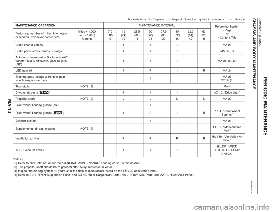
CHASSIS AND BODY MAINTENANCENBMA0004S0202
Abbreviations: R = Replace. I = Inspect. Correct or replace if necessary. L = Lubricate
MAINTENANCE OPERATIONMAINTENANCE INTERVAL
Reference Section
- Page
or
- Content Title Perform at number of miles, kilometers
or months, whichever comes first.Miles x 1,000
(km x 1,000)
Months7.5
(12)
615
(24)
1222.5
(36)
1830
(48)
2437.5
(60)
3045
(72)
3652.5
(84)
4260
(96)
48
Brake lines & cablesIIIIMA-25
Brake pads, rotors, drums & liningsIIIIMA-25, 26
Automatic transmission & all-mode 4WD
transfer fluid & differential gear oil (exc.
LSD)IIIIMA-21, 22, 23
LSD gear oilIRIRMA-24
Steering gear, linkage & transfer gear,
axle & suspension partsIIMA-26
NOTE (4)
Tire rotation NOTE (1)MA-4
Drive shaft boots (
) IIIIAX-10, ªDrive shaftº
Propeller shaft NOTE (2)LLLLMA-23
Front wheel bearing grease (4x2) I I
Front wheel bearing grease (
) IRIRAX-4, ªFront Wheel
Bearingº
Exhaust systemI I MA-21
Supplemental air bag systems NOTE (3)RS-14, ªMaintenance
Itemº
Ventilation air filterRRRRHA-159, ªVentilation Air
Filterº
ASCD vacuum hosesIIIIEL-237, ªASCD
ACTUATOR/PUMP
CHECKº
NOTE:
(1) Refer to ªTire rotationº under the ªGENERAL MAINTENANCEº heading earlier in this section.
(2) The propeller shaft should be re-greased after being immersed in water.
(3) Inspect the air bag system 10 years after the date of manufacture noted on the FMVSS certification label.
(4) Refer to SU-5, ªFront Suspension Partsº and SU-16, ªRear Suspension Partsº, AX-3, ªFront Axle Partsº and AX-18, ªRear Axle Partsº.
PERIODIC MAINTENANCE
Schedule 2 (Cont'd)
MA-10
Page 2006 of 2395
NBMA0005
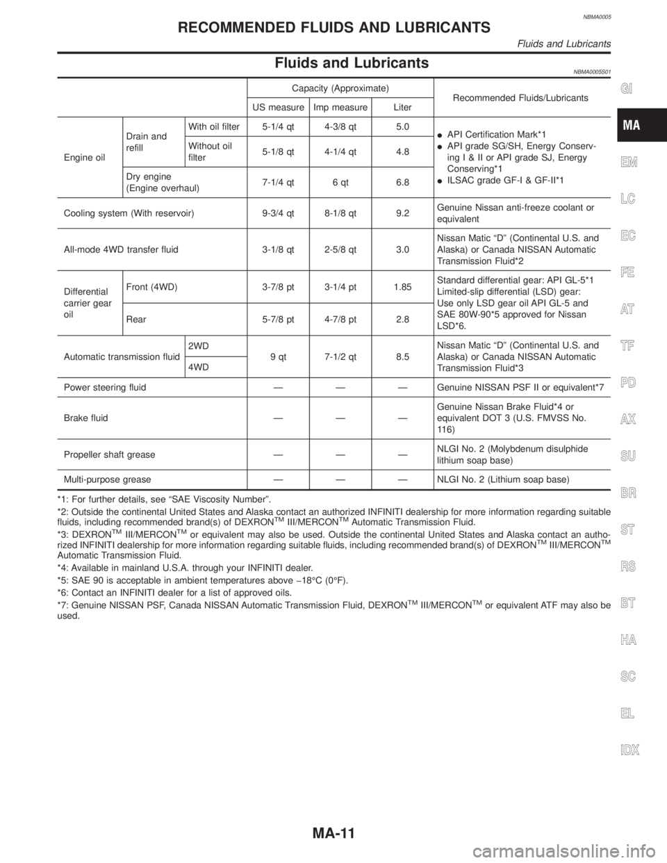
Fluids and LubricantsNBMA0005S01
Capacity (Approximate)
Recommended Fluids/Lubricants
US measure Imp measure Liter
Engine oilDrain and
refillWith oil filter 5-1/4 qt 4-3/8 qt 5.0
IAPI Certification Mark*1
IAPI grade SG/SH, Energy Conserv-
ingI&IIorAPIgrade SJ, Energy
Conserving*1
IILSAC grade GF-I & GF-II*1 Without oil
filter5-1/8 qt 4-1/4 qt 4.8
Dry engine
(Engine overhaul)7-1/4 qt 6 qt 6.8
Cooling system (With reservoir) 9-3/4 qt 8-1/8 qt 9.2Genuine Nissan anti-freeze coolant or
equivalent
All-mode 4WD transfer fluid 3-1/8 qt 2-5/8 qt 3.0Nissan Matic ªDº (Continental U.S. and
Alaska) or Canada NISSAN Automatic
Transmission Fluid*2
Differential
carrier gear
oilFront (4WD) 3-7/8 pt 3-1/4 pt 1.85Standard differential gear: API GL-5*1
Limited-slip differential (LSD) gear:
Use only LSD gear oil API GL-5 and
SAE 80W-90*5 approved for Nissan
LSD*6. Rear 5-7/8 pt 4-7/8 pt 2.8
Automatic transmission fluid2WD
9 qt 7-1/2 qt 8.5Nissan Matic ªDº (Continental U.S. and
Alaska) or Canada NISSAN Automatic
Transmission Fluid*3 4WD
Power steering fluid Ð Ð Ð Genuine NISSAN PSF II or equivalent*7
Brake fluid Ð Ð ÐGenuine Nissan Brake Fluid*4 or
equivalent DOT 3 (U.S. FMVSS No.
116)
Propeller shaft grease Ð Ð ÐNLGI No. 2 (Molybdenum disulphide
lithium soap base)
Multi-purpose grease Ð Ð Ð NLGI No. 2 (Lithium soap base)
*1: For further details, see ªSAE Viscosity Numberº.
*2: Outside the continental United States and Alaska contact an authorized INFINITI dealership for more information regarding suitable
fluids, including recommended brand(s) of DEXRON
TMIII/MERCONTMAutomatic Transmission Fluid.
*3: DEXRONTMIII/MERCONTMor equivalent may also be used. Outside the continental United States and Alaska contact an autho-
rized INFINITI dealership for more information regarding suitable fluids, including recommended brand(s) of DEXRONTMIII/MERCONTM
Automatic Transmission Fluid.
*4: Available in mainland U.S.A. through your INFINITI dealer.
*5: SAE 90 is acceptable in ambient temperatures above þ18ÉC (0ÉF).
*6: Contact an INFINITI dealer for a list of approved oils.
*7: Genuine NISSAN PSF, Canada NISSAN Automatic Transmission Fluid, DEXRON
TMIII/MERCONTMor equivalent ATF may also be
used.
GI
EM
LC
EC
FE
AT
TF
PD
AX
SU
BR
ST
RS
BT
HA
SC
EL
IDX
RECOMMENDED FLUIDS AND LUBRICANTS
Fluids and Lubricants
MA-11
Page 2008 of 2395

Checking Drive BeltsNBMA0010
SMA091D
1. Inspect belt for cracks, fraying, wear and oil. If necessary,
replace.
2. Inspect drive belt deflection or tension at a point on the belt
midway between pulleys.
3. Check belt tension using belt tension gauge (BT3373-F or
equivalent).
Inspect drive belt deflection or tension when engine is cold.
Adjust if belt deflections exceed the limit or if belt tension is
not within specifications.
Belt deflection and tension
Deflection adjustment Unit: mm (in) Tension adjustment *1 Unit: N (kg, lb)
Used belt
New beltUsed belt
New belt
Limit After adjustment Limit After adjustment
Alternator
Power steering
oil pump
Fan7 (0.28)4-5
(0.16 - 0.20)3.5 - 4.5
(0.138 - 0.177)294 (30, 66)730 - 818 (74.4 -
83.5, 164 - 184)838 - 926 (85.4 -
94.5, 188 - 208)
Air conditioner
compressor12 (0.47)9-10
(0.35 - 0.39)8-9
(0.31 - 0.35)196 (20, 44)348 - 436 (35.5 -
44.5, 78 - 98)470 - 559 (47.9 -
57.0, 106 - 126)
Applied pushing
force98 N (10 kg, 22 lb) Ð
*1 If belt tension gauge cannot be installed at check points shown, check drive belt tension at a different location on the belt.
GI
EM
LC
EC
FE
AT
TF
PD
AX
SU
BR
ST
RS
BT
HA
SC
EL
IDX
ENGINE MAINTENANCE
Checking Drive Belts
MA-13
Page 2021 of 2395
SMA848B
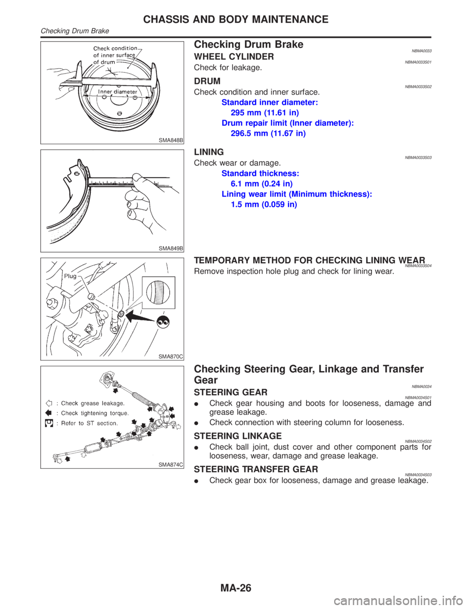
Checking Drum BrakeNBMA0033WHEEL CYLINDERNBMA0033S01Check for leakage.
DRUMNBMA0033S02Check condition and inner surface.
Standard inner diameter:
295 mm (11.61 in)
Drum repair limit (Inner diameter):
296.5 mm (11.67 in)
SMA849B
LININGNBMA0033S03Check wear or damage.
Standard thickness:
6.1 mm (0.24 in)
Lining wear limit (Minimum thickness):
1.5 mm (0.059 in)
SMA870C
TEMPORARY METHOD FOR CHECKING LINING WEARNBMA0033S04Remove inspection hole plug and check for lining wear.
SMA874C
Checking Steering Gear, Linkage and Transfer
Gear
NBMA0034STEERING GEARNBMA0034S01ICheck gear housing and boots for looseness, damage and
grease leakage.
ICheck connection with steering column for looseness.
STEERING LINKAGENBMA0034S02ICheck ball joint, dust cover and other component parts for
looseness, wear, damage and grease leakage.
STEERING TRANSFER GEARNBMA0034S03ICheck gear box for looseness, damage and grease leakage.
CHASSIS AND BODY MAINTENANCE
Checking Drum Brake
MA-26
Page 2022 of 2395
SST280B
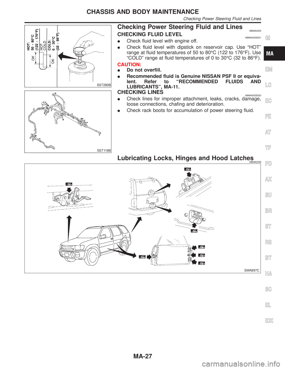
Checking Power Steering Fluid and LinesNBMA0035CHECKING FLUID LEVELNBMA0035S01ICheck fluid level with engine off.
ICheck fluid level with dipstick on reservoir cap. Use ªHOTº
range at fluid temperatures of 50 to 80ÉC (122 to 176ÉF). Use
ªCOLDº range at fluid temperatures of 0 to 30ÉC (32 to 86ÉF).
CAUTION:
IDo not overfill.
IRecommended fluid is Genuine NISSAN PSF II or equiva-
lent. Refer to ªRECOMMENDED FLUIDS AND
LUBRICANTSº, MA-11.
SST118B
CHECKING LINESNBMA0035S02ICheck lines for improper attachment, leaks, cracks, damage,
loose connections, chafing and deterioration.
ICheck rack boots for accumulation of power steering fluid.
Lubricating Locks, Hinges and Hood LatchesNBMA0036
SMA897C
GI
EM
LC
EC
FE
AT
TF
PD
AX
SU
BR
ST
RS
BT
HA
SC
EL
IDX
CHASSIS AND BODY MAINTENANCE
Checking Power Steering Fluid and Lines
MA-27
Page 2024 of 2395
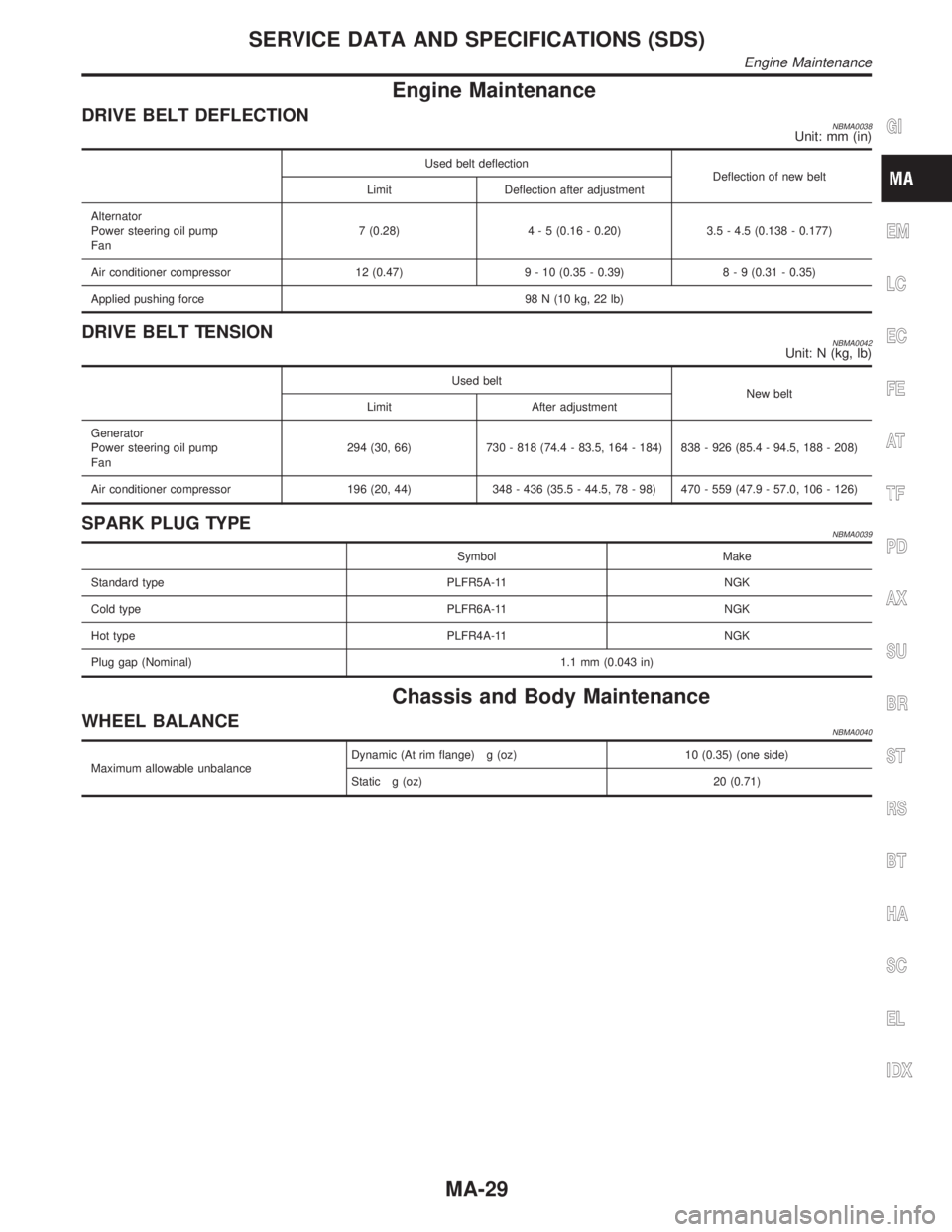
Engine Maintenance
DRIVE BELT DEFLECTIONNBMA0038Unit: mm (in)
Used belt deflection
Deflection of new belt
Limit Deflection after adjustment
Alternator
Power steering oil pump
Fan7 (0.28)4 - 5 (0.16 - 0.20) 3.5 - 4.5 (0.138 - 0.177)
Air conditioner compressor 12 (0.47) 9 - 10 (0.35 - 0.39)8 - 9 (0.31 - 0.35)
Applied pushing force 98 N (10 kg, 22 lb)
DRIVE BELT TENSIONNBMA0042Unit: N (kg, lb)
Used belt
New belt
Limit After adjustment
Generator
Power steering oil pump
Fan294 (30, 66) 730 - 818 (74.4 - 83.5, 164 - 184) 838 - 926 (85.4 - 94.5, 188 - 208)
Air conditioner compressor 196 (20, 44) 348 - 436 (35.5 - 44.5, 78 - 98) 470 - 559 (47.9 - 57.0, 106 - 126)
SPARK PLUG TYPENBMA0039
Symbol Make
Standard type PLFR5A-11 NGK
Cold type PLFR6A-11 NGK
Hot type PLFR4A-11 NGK
Plug gap (Nominal) 1.1 mm (0.043 in)
Chassis and Body Maintenance
WHEEL BALANCENBMA0040
Maximum allowable unbalanceDynamic (At rim flange) g (oz) 10 (0.35) (one side)
Static g (oz) 20 (0.71)
GI
EM
LC
EC
FE
AT
TF
PD
AX
SU
BR
ST
RS
BT
HA
SC
EL
IDX
SERVICE DATA AND SPECIFICATIONS (SDS)
Engine Maintenance
MA-29
Page 2028 of 2395
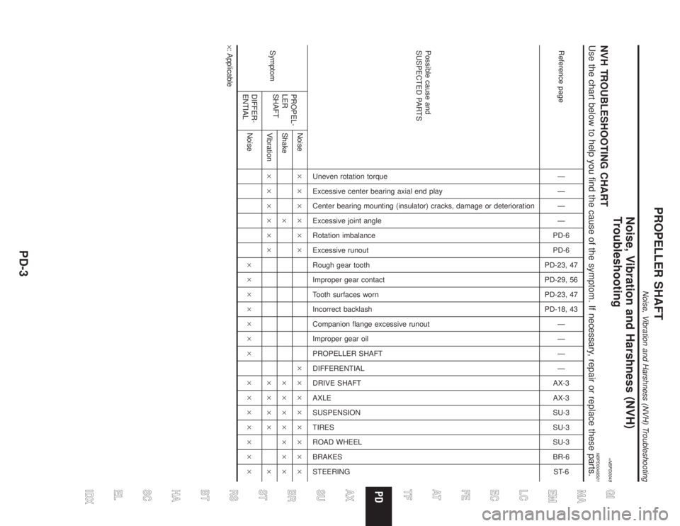
Noise, Vibration and Harshness (NVH)
Troubleshooting
=NBPD0049NVH TROUBLESHOOTING CHARTNBPD0049S01Use the chart below to help you find the cause of the symptom. If necessary, repair or replace these parts.
Reference pageÐ
Ð
Ð
Ð
PD-6
PD-6
PD-23, 47
PD-29, 56
PD-23, 47
PD-18, 43
Ð
Ð
Ð
Ð
AX-3
AX-3
SU-3
SU-3
SU-3
BR-6
ST-6
Possible cause and
SUSPECTED PARTS
Uneven rotation torque
Excessive center bearing axial end play
Center bearing mounting (insulator) cracks, damage or deterioration
Excessive joint angle
Rotation imbalance
Excessive runout
Rough gear tooth
Improper gear contact
Tooth surfaces worn
Incorrect backlash
Companion flange excessive runout
Improper gear oil
PROPELLER SHAFT
DIFFERENTIAL
DRIVE SHAFT
AXLE
SUSPENSION
TIRES
ROAD WHEEL
BRAKES
STEERING
SymptomPROPEL-
LER
SHAFTNoise´´´´´´ ´´´´´´´´
Shake´ ´´´´´´´
Vibration´´´´´´ ´´´´ ´
DIFFER-
ENTIALNoise´´´´´´´ ´´´´´´´
´: Applicable
GI
MA
EM
LC
EC
FE
AT
TF
AX
SU
BR
ST
RS
BT
HA
SC
EL
IDX
PROPELLER SHAFT
Noise, Vibration and Harshness (NVH) Troubleshooting
PD-3
Page 2099 of 2395
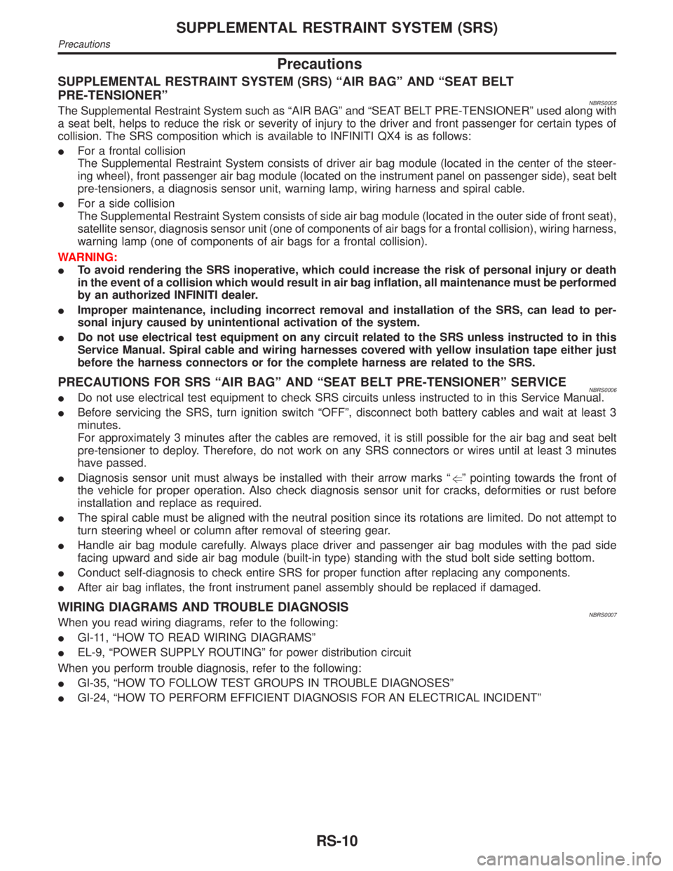
Precautions
SUPPLEMENTAL RESTRAINT SYSTEM (SRS) ªAIR BAGº AND ªSEAT BELT
PRE-TENSIONERº
NBRS0005The Supplemental Restraint System such as ªAIR BAGº and ªSEAT BELT PRE-TENSIONERº used along with
a seat belt, helps to reduce the risk or severity of injury to the driver and front passenger for certain types of
collision. The SRS composition which is available to INFINITI QX4 is as follows:
IFor a frontal collision
The Supplemental Restraint System consists of driver air bag module (located in the center of the steer-
ing wheel), front passenger air bag module (located on the instrument panel on passenger side), seat belt
pre-tensioners, a diagnosis sensor unit, warning lamp, wiring harness and spiral cable.
IFor a side collision
The Supplemental Restraint System consists of side air bag module (located in the outer side of front seat),
satellite sensor, diagnosis sensor unit (one of components of air bags for a frontal collision), wiring harness,
warning lamp (one of components of air bags for a frontal collision).
WARNING:
ITo avoid rendering the SRS inoperative, which could increase the risk of personal injury or death
in the event of a collision which would result in air bag inflation, all maintenance must be performed
by an authorized INFINITI dealer.
IImproper maintenance, including incorrect removal and installation of the SRS, can lead to per-
sonal injury caused by unintentional activation of the system.
IDo not use electrical test equipment on any circuit related to the SRS unless instructed to in this
Service Manual. Spiral cable and wiring harnesses covered with yellow insulation tape either just
before the harness connectors or for the complete harness are related to the SRS.
PRECAUTIONS FOR SRS ªAIR BAGº AND ªSEAT BELT PRE-TENSIONERº SERVICENBRS0006IDo not use electrical test equipment to check SRS circuits unless instructed to in this Service Manual.
IBefore servicing the SRS, turn ignition switch ªOFFº, disconnect both battery cables and wait at least 3
minutes.
For approximately 3 minutes after the cables are removed, it is still possible for the air bag and seat belt
pre-tensioner to deploy. Therefore, do not work on any SRS connectors or wires until at least 3 minutes
have passed.
IDiagnosis sensor unit must always be installed with their arrow marks ªgº pointing towards the front of
the vehicle for proper operation. Also check diagnosis sensor unit for cracks, deformities or rust before
installation and replace as required.
IThe spiral cable must be aligned with the neutral position since its rotations are limited. Do not attempt to
turn steering wheel or column after removal of steering gear.
IHandle air bag module carefully. Always place driver and passenger air bag modules with the pad side
facing upward and side air bag module (built-in type) standing with the stud bolt side setting bottom.
IConduct self-diagnosis to check entire SRS for proper function after replacing any components.
IAfter air bag inflates, the front instrument panel assembly should be replaced if damaged.
WIRING DIAGRAMS AND TROUBLE DIAGNOSISNBRS0007When you read wiring diagrams, refer to the following:
IGI-11, ªHOW TO READ WIRING DIAGRAMSº
IEL-9, ªPOWER SUPPLY ROUTINGº for power distribution circuit
When you perform trouble diagnosis, refer to the following:
IGI-35, ªHOW TO FOLLOW TEST GROUPS IN TROUBLE DIAGNOSESº
IGI-24, ªHOW TO PERFORM EFFICIENT DIAGNOSIS FOR AN ELECTRICAL INCIDENTº
SUPPLEMENTAL RESTRAINT SYSTEM (SRS)
Precautions
RS-10