2001 INFINITI QX4 steering
[x] Cancel search: steeringPage 1215 of 2395

CheckNBEL0011
MEL133M
STEERING SWITCH
Check
EL-30
Page 1407 of 2395
System DescriptionNBEL0216Refer to Owner's Manual for ASCD operating instructions.
POWER SUPPLY AND GROUNDNBEL0216S01Power is supplied at all times:
Ithrough 10A fuse [No. 14, located in the fuse block (J/B)]
Ito the stop lamp switch terminal 1, and
Ithrough 7.5A fuse (No. 52, located in fuse and fusible link box)
Ito the horn relay terminals 1 and 3.
When ignition switch is in the ON or START position, power is supplied:
Ithrough 7.5A fuse [No. 11, located in the fuse block (J/B)]
Ito ASCD brake switch terminal 1 and
Ito ASCD control unit terminal 5,
Ithrough 10A fuse [No. 18, located in the fuse block (J/B)]
Ito park/neutral position relay terminal 1,
Ithrough 10A fuse [No. 8, located in the fuse block (J/B)]
Ito combination meter terminal 66, and
When park/neutral position switch is in the P or N position, ground is supplied:
Ito park/neutral position relay terminal 2
Ithrough park/neutral position switch and body grounds B55 and B75.
When ASCD main switch is depressed (ON), ground is supplied:
Ito ASCD control unit terminal 9
Ifrom ASCD steering switch terminal 4
Ito ASCD steering switch terminal 5
Ithrough body grounds M4, M66 and M147
then ASCD control unit holds CRUISE condition and illuminates CRUISE indicator.
Ground is supplied:
Ifrom ASCD control unit terminal 15
Ito combination meter terminal 46.
OPERATIONNBEL0216S02Set OperationNBEL0216S0201To activate the ASCD, all following conditions must exist.
IGround supply to ASCD control unit terminal 9 (Main switch is in ON position.)
IPower supply to ASCD control unit terminal 8 (Brake pedal is released and A/T selector lever is in other
than P and N position.)
IVehicle speed is between 40 km/h (25 MPH) and 144 km/h (89 MPH). (Signal from combination meter)
When the SET/COAST switch is depressed, power is supplied:
Ifrom ASCD steering switch terminal 2
Ito ASCD control unit terminal 11.
And then ASCD pump is activated to control throttle wire and ASCD control unit supply ground
Ito combination meter terminals 51 to illuminate SET indicator.
A/T Overdrive Control during Cruise Control DrivingNBEL0216S0202When the vehicle speed is approximately 3 km/h (2 MPH) below set speed, a signal is sent
Ifrom ASCD control unit terminal 10
Ito TCM (transmission control module) terminal 24.
When this occurs, the TCM (transmission control module) cancels overdrive.
After vehicle speed is approximately 1 km/h (1 MPH) below set speed, overdrive is reactivated.
ASCD Shifting ControlNBEL0216S0203During ASCD cruise, ASCD control unit controls A/T shifting to avoid uncomfortable shifting.
This is used to control the signals below.
IThrottle position sensor from ECM
AUTOMATIC SPEED CONTROL DEVICE (ASCD)
System Description
EL-222
Page 1408 of 2395
IA/T shift solenoid valve A
Coast OperationNBEL0216S0204When the SET/COAST switch is depressed during cruise control driving, ASCD actuator returns the throttle
cable to decrease vehicle set speed until the switch is released. And then ASCD will keep the new set speed.
Accel OperationNBEL0216S0205When the RESUME/ACCEL switch is depressed, power is supplied
Ifrom ASCD steering switch terminal 3
Ito ASCD control unit terminal 24.
If the RESUME/ACCEL switch is depressed during cruise control driving, ASCD actuator pulls the throttle cable
to increase the vehicle speed until the switch is released or vehicle speed is reached to maximum controlled
speed by the system. And then ASCD will keep the new set speed.
Cancel OperationNBEL0216S0206When any of following condition exists, cruise operation will be canceled.
ICANCEL switch is depressed. (Power supply to ASCD control unit terminals 11 and 24)
IBrake pedal is depressed. (Power supply to ASCD control unit terminal 23 from stop lamp switch)
IBrake pedal is depressed or A/T selector lever is shifted to P or N position. (Power supply to ASCD con-
trol unit terminal 8 is interrupted.)
If MAIN switch is turned to OFF during ASCD is activated, all of ASCD operation will be canceled and vehicle
speed memory will be erased.
Resume OperationNBEL0216S0207When the RESUME/ACCEL switch is depressed after cancel operation other than depressing MAIN switch is
performed, vehicle speed will return to last set speed. To resume vehicle set speed, vehicle condition must
meet following conditions.
IBrake pedal is released.
IA/T selector lever is in other than P and N position.
IVehicle speed is between 40 km/h (25 MPH) and 144 km/h (89 MPH).
ASCD PUMP OPERATIONNBEL0216S03The ASCD pump consists of a vacuum motor, an air valve and a release valve. When the ASCD activates,
power is supplied
Ifrom terminal 12 of ASCD control unit
Ito ASCD pump terminal 1.
Ground is supplied to vacuum motor, air valve and release valve from ASCD control unit depending on the
operated condition as shown in the below table.
The pump is connected to ASCD actuator by vacuum hose. When the ASCD pump is activated, the ASCD
pump vacuum the diaphragm of ASCD actuator to control throttle cable.
Air valve (*1) Release valve (*1) Vacuum motorActuator inner pres-
sure
ASCD not operating Open Open Stopped Atmosphere
ASCD operatingReleasing throttle
cableOpen Closed Stopped Vacuum
Holding throttle
positionClosed Closed Stopped Vacuum (*2)
Pulling throttle cable Closed Closed Operated Vacuum
*1: When power and ground is supplied, valve is closed.
*2: Set position held.
GI
MA
EM
LC
EC
FE
AT
TF
PD
AX
SU
BR
ST
RS
BT
HA
SC
IDX
AUTOMATIC SPEED CONTROL DEVICE (ASCD)
System Description (Cont'd)
EL-223
Page 1414 of 2395

SEL255W
Fail-safe SystemNBEL0217DESCRIPTIONNBEL0217S01When the fail-safe system senses a malfunction, it deactivates
ASCD operation. The SET indicator in the combination meter will
then flash.
MALFUNCTION DETECTION CONDITIONSNBEL0217S02
Detection conditionsASCD operation during malfunc-
tion detection
IASCD steering (RESUME/ACCEL, CANCEL, SET/COAST) switch is stuck.
IVacuum motor ground circuit or power circuit is open or shorted.
IAir valve ground circuit or power circuit is open or shorted.
IRelease valve ground circuit or power circuit is open or shorted.
IVehicle speed sensor is faulty.
IASCD control unit internal circuit is malfunctioning.IASCD is deactivated.
IVehicle speed memory is can-
celed.
IASCD brake switch or stop lamp switch is faulty.IASCD is deactivated.
IVehicle speed memory is not
canceled.
GI
MA
EM
LC
EC
FE
AT
TF
PD
AX
SU
BR
ST
RS
BT
HA
SC
IDX
AUTOMATIC SPEED CONTROL DEVICE (ASCD)
Fail-safe System
EL-229
Page 1415 of 2395
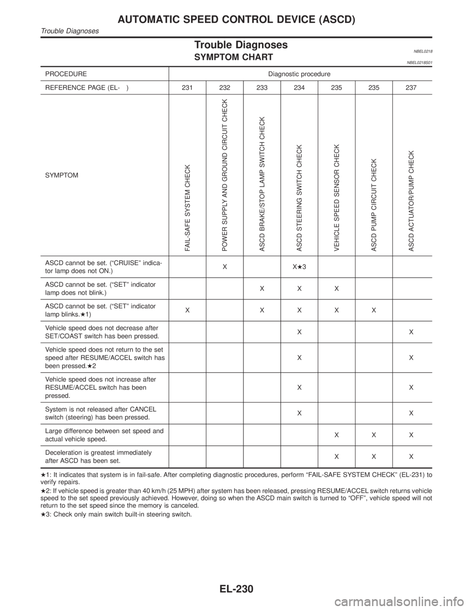
Trouble DiagnosesNBEL0218SYMPTOM CHARTNBEL0218S01
PROCEDURE Diagnostic procedure
REFERENCE PAGE (EL- ) 231 232 233 234 235 235 237
SYMPTOM
FAIL-SAFE SYSTEM CHECK
POWER SUPPLY AND GROUND CIRCUIT CHECK
ASCD BRAKE/STOP LAMP SWITCH CHECK
ASCD STEERING SWITCH CHECK
VEHICLE SPEED SENSOR CHECK
ASCD PUMP CIRCUIT CHECK
ASCD ACTUATOR/PUMP CHECK
ASCD cannot be set. (ªCRUISEº indica-
tor lamp does not ON.)XXH3
ASCD cannot be set. (ªSETº indicator
lamp does not blink.)XXX
ASCD cannot be set. (ªSETº indicator
lamp blinks.H1)X XXXX
Vehicle speed does not decrease after
SET/COAST switch has been pressed.XX
Vehicle speed does not return to the set
speed after RESUME/ACCEL switch has
been pressed.H2XX
Vehicle speed does not increase after
RESUME/ACCEL switch has been
pressed.XX
System is not released after CANCEL
switch (steering) has been pressed.XX
Large difference between set speed and
actual vehicle speed.XXX
Deceleration is greatest immediately
after ASCD has been set.XXX
H1: It indicates that system is in fail-safe. After completing diagnostic procedures, perform ªFAIL-SAFE SYSTEM CHECKº (EL-231) to
verify repairs.
H2: If vehicle speed is greater than 40 km/h (25 MPH) after system has been released, pressing RESUME/ACCEL switch returns vehicle
speed to the set speed previously achieved. However, doing so when the ASCD main switch is turned to ªOFFº, vehicle speed will not
return to the set speed since the memory is canceled.
H3: Check only main switch built-in steering switch.
AUTOMATIC SPEED CONTROL DEVICE (ASCD)
Trouble Diagnoses
EL-230
Page 1416 of 2395
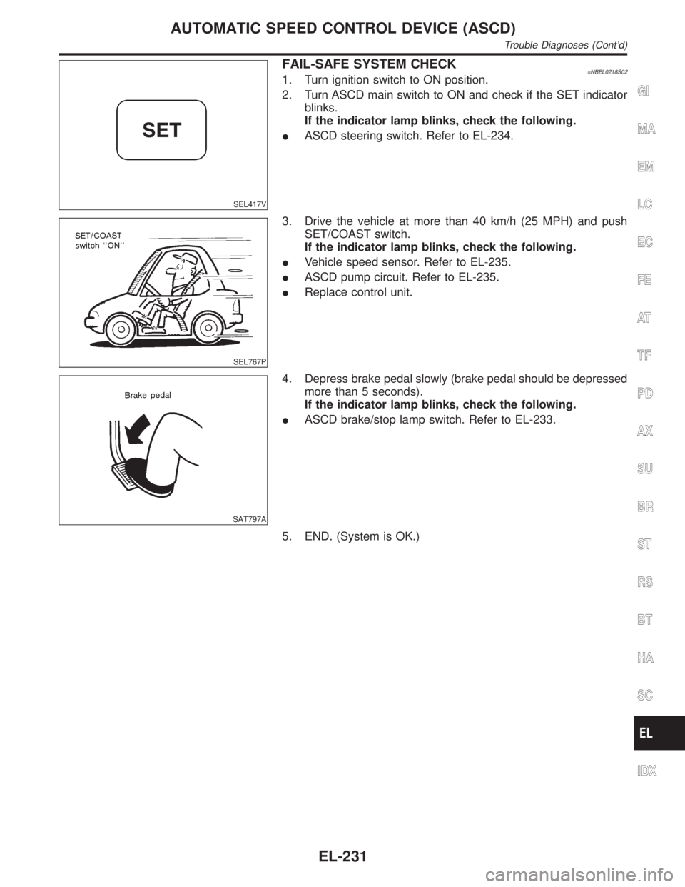
SEL417V
FAIL-SAFE SYSTEM CHECK=NBEL0218S021. Turn ignition switch to ON position.
2. Turn ASCD main switch to ON and check if the SET indicator
blinks.
If the indicator lamp blinks, check the following.
IASCD steering switch. Refer to EL-234.
SEL767P
3. Drive the vehicle at more than 40 km/h (25 MPH) and push
SET/COAST switch.
If the indicator lamp blinks, check the following.
IVehicle speed sensor. Refer to EL-235.
IASCD pump circuit. Refer to EL-235.
IReplace control unit.
SAT797A
4. Depress brake pedal slowly (brake pedal should be depressed
more than 5 seconds).
If the indicator lamp blinks, check the following.
IASCD brake/stop lamp switch. Refer to EL-233.
5. END. (System is OK.)
GI
MA
EM
LC
EC
FE
AT
TF
PD
AX
SU
BR
ST
RS
BT
HA
SC
IDX
AUTOMATIC SPEED CONTROL DEVICE (ASCD)
Trouble Diagnoses (Cont'd)
EL-231
Page 1419 of 2395
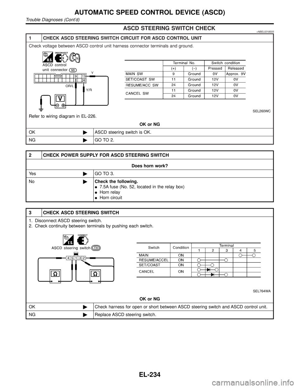
ASCD STEERING SWITCH CHECK=NBEL0218S05
1 CHECK ASCD STEERING SWITCH CIRCUIT FOR ASCD CONTROL UNIT
Check voltage between ASCD control unit harness connector terminals and ground.
SEL260WC
Refer to wiring diagram in EL-226.
OK or NG
OK©ASCD steering switch is OK.
NG©GO TO 2.
2 CHECK POWER SUPPLY FOR ASCD STEERING SWITCH
Does horn work?
Ye s©GO TO 3.
No©Check the following.
I7.5A fuse (No. 52, located in the relay box)
IHorn relay
IHorn circuit
3 CHECK ASCD STEERING SWITCH
1. Disconnect ASCD steering switch.
2. Check continuity between terminals by pushing each switch.
SEL764WA
OK or NG
OK©Check harness for open or short between ASCD steering switch and ASCD control unit.
NG©Replace ASCD steering switch.
AUTOMATIC SPEED CONTROL DEVICE (ASCD)
Trouble Diagnoses (Cont'd)
EL-234
Page 1555 of 2395
NOTE:
After replacing IVCS unit, set up the replaced IVCS unit. Refer
to ªSystem Setting (When IVCS Unit is Replaced.)º in EL-381.
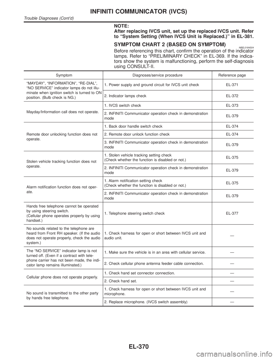
SYMPTOM CHART 2 (BASED ON SYMPTOM)NBEL0184S04Before referencing this chart, confirm the operation of the indicator
lamps. Refer to ªPRELIMINARY CHECKº in EL-369. If the indica-
tors show the system is malfunctioning, perform the self-diagnosis
using CONSULT-II.
Symptom Diagnoses/service procedure Reference page
ªMAYDAYº, ªINFORMATIONº, ªRE-DIALº,
ªNO SERVICEº indicator lamps do not illu-
minate when ignition switch is turned to ON
position. (Bulb check is NG.)1. Power supply and ground circuit for IVCS unit check EL-371
2. Indicator lamps check EL-372
Mayday/Information call does not operate.1. IVCS switch check EL-373
2. INFINITI Communicator operation check in demonstration
modeEL-379
Remote door unlocking function does not
operate.1. Back door handle switch check EL-374
2. Remote door unlock function check EL-374
3. INFINITI Communicator operation check in demonstration
modeEL-379
Stolen vehicle tracking function does not
operate.1. Stolen vehicle tracking setting check
(Check whether the function is disabled or not.)EL-375
2. INFINITI Communicator operation check in demonstration
modeEL-379
Alarm notification function does not oper-
ate.1. Alarm notification setting check
(Check whether the function is disabled or not.)EL-375
2. INFINITI Communicator operation check in demonstration
modeEL-379
Hands free telephone cannot be operated
by using steering switch.
(Cellular phone operates properly by using
handset.)1. Telephone steering switch check EL-377
No sounds related to the telephone are
heard from Front RH speaker. (If the audio
does not operate properly, check the audio
system.)1. Check harness for open or short between IVCS unit and
audio unit.Ð
The ªNO SERVICEº indicator lamp is not
turned off. (Even if a contract with tele-
phone carrier has not been made, the indi-
cator lamp remains illuminated.)1. Make sure the vehicle is in an area with cellular service. Ð
2. Check cellular phone antenna feeder cable connection. Ð
Cellular phone does not operate properly.1. Check hand set connector connection. Ð
2. Check hand set. Ð
No sound is transmitted to the other party
by hands free telephone.1. Check harness for open or short between IVCS unit and
microphone.Ð
2. Replace microphone. (IVCS switch assembly) Ð
INFINITI COMMUNICATOR (IVCS)
Trouble Diagnoses (Cont'd)
EL-370