Page 2248 of 2395

CONTROL SYSTEM DIAGRAMNBTF0007S04
SMT763D
INDICATIONS OF 4WD WARNING LAMPNBTF0007S05
Condition Content 4WD warning lamp
During self-diagnosis Indicates the malfunction position by number of flickers. Flickers at malfunction mode.
Lamp check*Checks the lamp by turning ON during engine starting. After
engine starts, it turns OFF if there are no malfunctions.ON
Malfunction in 4WD system*Turns ON to indicate malfunction. When ignition switch is
turned to ªOFFº or the malfunction is corrected, it turns OFF.ON
When vehicle is driven with different
diameters of front and rear tiresFlickers once every 2 seconds.
Turns OFF when ignition switch is ªOFFº.Flickers once every 2 sec-
onds.
High fluid temperature in transfer
unitWhen fluid temperature is high or fluid temperature sensor
circuit is shorted, it flickers twice every second.
It turns OFF when fluid temperature becomes normal.Flickers twice a second.
Other than above (System is nor-
mal.)Lamp is OFF. OFF
*: When 4WD warning lamp is ON, all the 4WD shift indicator lamps turn OFF.
GI
MA
EM
LC
EC
FE
AT
PD
AX
SU
BR
ST
RS
BT
HA
SC
EL
IDX
ALL-MODE 4WD SYSTEM
Control System (Cont'd)
TF-13
Page 2262 of 2395
Trouble Diagnosis without CONSULT-IINBTF0011DESCRIPTIONNBTF0011S01If the engine starts when there is something wrong with the all-
mode 4WD system, the 4WD warning lamp turns ON or flickers in
the combination meter. When the system functions properly, the
warning lamp turns ON when the ignition switch is turned to ªONº,
and it turns OFF after engine starts.
To locate the cause of a problem, start the self-diagnosis function.
The 4WD warning lamp in the combination meter will indicate the
problem area by flickering according to the self-diagnostic results.
As for the details of the 4WD warning lamp flickering patterns, refer
to TF-29.GI
MA
EM
LC
EC
FE
AT
PD
AX
SU
BR
ST
RS
BT
HA
SC
EL
IDX
ON BOARD DIAGNOSTIC SYSTEM DESCRIPTION
Trouble Diagnosis without CONSULT-II
TF-27
Page 2265 of 2395
Flickering pattern or flick-
ering conditionMalfunction Check items
No flickering PNP switch or 4WD shift switch circuit is shorted or open.PNP switch (Refer to AT-99, ªDTC
P0705 Park/Neutral Position
Switchº.) or 4WD shift switch circuit,
TF-66.
*: If revolution sensor malfunction is simultaneously detected, check revolution sensor first.
SAT601J
Trouble Diagnosis with CONSULT-IINBTF0012SELF-DIAGNOSISNBTF0012S01CONSULT-II Setting ProcedureNBTF0012S01011. Turn ignition switch to ªOFFº position.
SMT962D
2. Connect CONSULT-II to data link connector which is located
in instrument lower panel on driver side.
SAT586J
3. Start engine.
4. On CONSULT-II screen, touch ªSTARTº.
SMT964D
5. Touch ªALL MODE 4WDº on SELECT SYSTEM screen.
ON BOARD DIAGNOSTIC SYSTEM DESCRIPTION
Trouble Diagnosis without CONSULT-II (Cont'd)
TF-30
Page 2268 of 2395
SMT962D
DATA MONITORNBTF0012S03CONSULT-II Setting ProcedureNBTF0012S03011. Turn ignition switch to ªOFFº position.
2. Connect CONSULT-II to data link connector, which is located
in instrument lower panel on driver side.
3. Turn ignition switch to ªONº position.
4. Touch ªSTARTº.
SMT964D
5. Touch ªALL MODE 4WDº.
SMT965D
6. Touch ªDATA MONITORº.
SAT972J
7. Touch ªECU INPUT SIGNALSº or ªMAIN SIGNALSº.
8. Select ªNumerical Displayº, ªBar Chart Displayº or ªLine Graph
Displayº.
9. Touch ªSETTINGº to set record conditions.
SAT973J
10. Touch ªAUTO TRIGº or ªMANU TRIGº.
11. Return to ªSELECT MONITOR ITEMº on ªDATA MONITORº
screen and touch ªSTARTº.
GI
MA
EM
LC
EC
FE
AT
PD
AX
SU
BR
ST
RS
BT
HA
SC
EL
IDX
ON BOARD DIAGNOSTIC SYSTEM DESCRIPTION
Trouble Diagnosis with CONSULT-II (Cont'd)
TF-33
Page 2271 of 2395

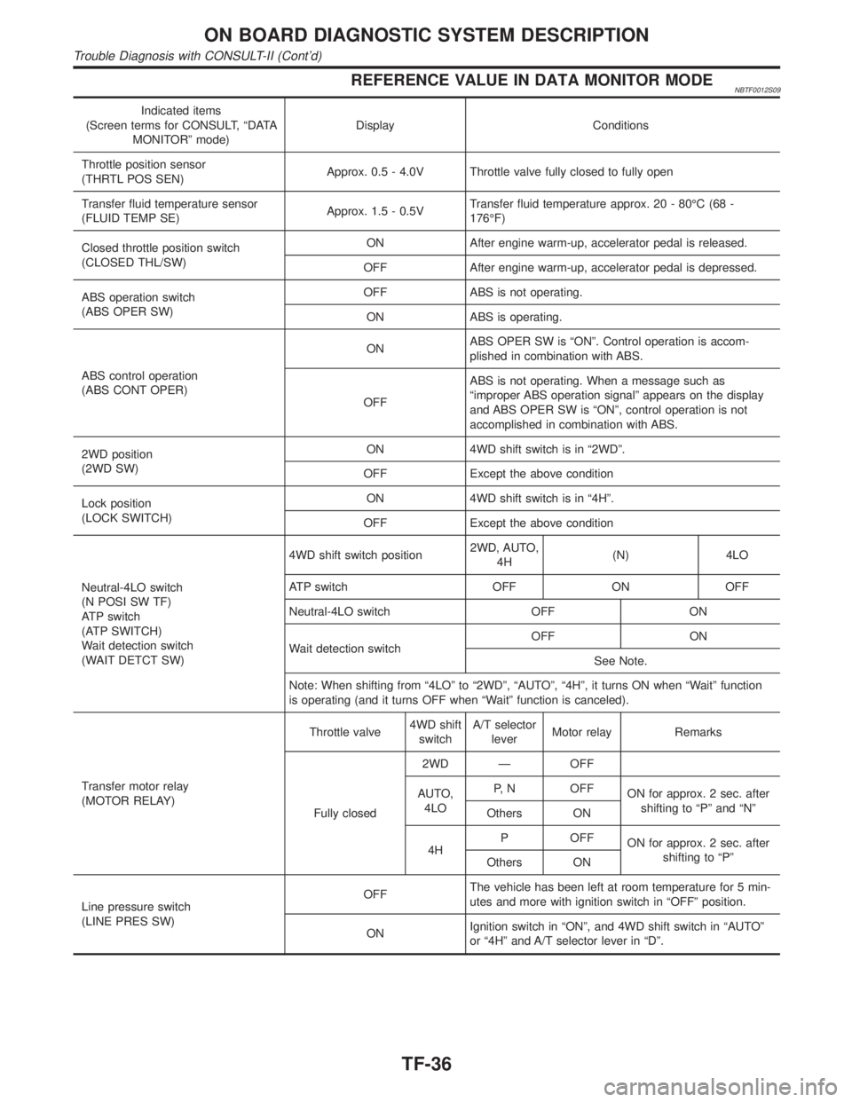
REFERENCE VALUE IN DATA MONITOR MODENBTF0012S09
Indicated items
(Screen terms for CONSULT, ªDATA
MONITORº mode)Display Conditions
Throttle position sensor
(THRTL POS SEN)Approx. 0.5 - 4.0V Throttle valve fully closed to fully open
Transfer fluid temperature sensor
(FLUID TEMP SE)Approx. 1.5 - 0.5VTransfer fluid temperature approx. 20 - 80ÉC (68 -
176ÉF)
Closed throttle position switch
(CLOSED THL/SW)ON After engine warm-up, accelerator pedal is released.
OFF After engine warm-up, accelerator pedal is depressed.
ABS operation switch
(ABS OPER SW)OFF ABS is not operating.
ON ABS is operating.
ABS control operation
(ABS CONT OPER)ONABS OPER SW is ªONº. Control operation is accom-
plished in combination with ABS.
OFFABS is not operating. When a message such as
ªimproper ABS operation signalº appears on the display
and ABS OPER SW is ªONº, control operation is not
accomplished in combination with ABS.
2WD position
(2WD SW)ON 4WD shift switch is in ª2WDº.
OFF Except the above condition
Lock position
(LOCK SWITCH)ON 4WD shift switch is in ª4Hº.
OFF Except the above condition
Neutral-4LO switch
(N POSI SW TF)
ATP switch
(ATP SWITCH)
Wait detection switch
(WAIT DETCT SW)4WD shift switch position2WD, AUTO,
4H(N) 4LO
ATP switch OFF ON OFF
Neutral-4LO switch OFF ON
Wait detection switchOFF ON
See Note.
Note: When shifting from ª4LOº to ª2WDº, ªAUTOº, ª4Hº, it turns ON when ªWaitº function
is operating (and it turns OFF when ªWaitº function is canceled).
Transfer motor relay
(MOTOR RELAY)Throttle valve4WD shift
switchA/T selector
leverMotor relay Remarks
Fully closed2WD Ð OFF
AUTO,
4LOP, N OFF
ON for approx. 2 sec. after
shifting to ªPº and ªNº
Others ON
4HP OFF
ON for approx. 2 sec. after
shifting to ªPº
Others ON
Line pressure switch
(LINE PRES SW)OFFThe vehicle has been left at room temperature for 5 min-
utes and more with ignition switch in ªOFFº position.
ONIgnition switch in ªONº, and 4WD shift switch in ªAUTOº
or ª4Hº and A/T selector lever in ªDº.
ON BOARD DIAGNOSTIC SYSTEM DESCRIPTION
Trouble Diagnosis with CONSULT-II (Cont'd)
TF-36
Page 2272 of 2395

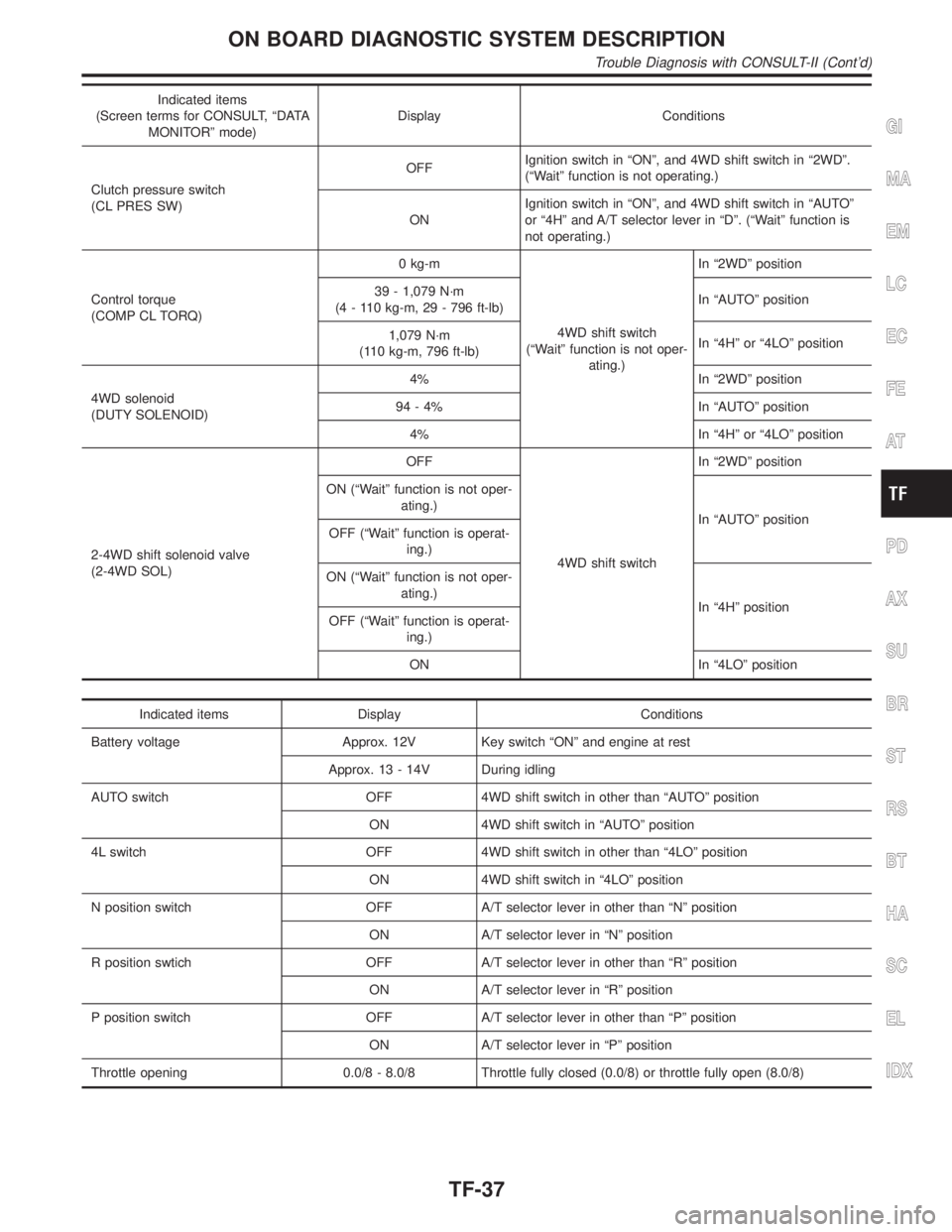
Indicated items
(Screen terms for CONSULT, ªDATA
MONITORº mode)Display Conditions
Clutch pressure switch
(CL PRES SW)OFFIgnition switch in ªONº, and 4WD shift switch in ª2WDº.
(ªWaitº function is not operating.)
ONIgnition switch in ªONº, and 4WD shift switch in ªAUTOº
or ª4Hº and A/T selector lever in ªDº. (ªWaitº function is
not operating.)
Control torque
(COMP CL TORQ)0 kg-m
4WD shift switch
(ªWaitº function is not oper-
ating.)In ª2WDº position
39 - 1,079 N´m
(4 - 110 kg-m, 29 - 796 ft-lb)In ªAUTOº position
1,079 N´m
(110 kg-m, 796 ft-lb)In ª4Hº or ª4LOº position
4WD solenoid
(DUTY SOLENOID)4% In ª2WDº position
94 - 4% In ªAUTOº position
4% In ª4Hº or ª4LOº position
2-4WD shift solenoid valve
(2-4WD SOL)OFF
4WD shift switchIn ª2WDº position
ON (ªWaitº function is not oper-
ating.)
In ªAUTOº position
OFF (ªWaitº function is operat-
ing.)
ON (ªWaitº function is not oper-
ating.)
In ª4Hº position
OFF (ªWaitº function is operat-
ing.)
ON In ª4LOº position
Indicated items Display Conditions
Battery voltage Approx. 12V Key switch ªONº and engine at rest
Approx. 13 - 14V During idling
AUTO switch OFF 4WD shift switch in other than ªAUTOº position
ON 4WD shift switch in ªAUTOº position
4L switch OFF 4WD shift switch in other than ª4LOº position
ON 4WD shift switch in ª4LOº position
N position switch OFF A/T selector lever in other than ªNº position
ON A/T selector lever in ªNº position
R position swtich OFF A/T selector lever in other than ªRº position
ON A/T selector lever in ªRº position
P position switch OFF A/T selector lever in other than ªPº position
ON A/T selector lever in ªPº position
Throttle opening 0.0/8 - 8.0/8 Throttle fully closed (0.0/8) or throttle fully open (8.0/8)
GI
MA
EM
LC
EC
FE
AT
PD
AX
SU
BR
ST
RS
BT
HA
SC
EL
IDX
ON BOARD DIAGNOSTIC SYSTEM DESCRIPTION
Trouble Diagnosis with CONSULT-II (Cont'd)
TF-37
Page 2274 of 2395

solved by this method. Refer to SYMPTOM 8, TF-108.
2) A slight shock is felt at a few hertz as if it were being pushed
lightly from behind.
SMT962D
CONSULT-II Setting ProcedureNBTF0012S06021. Turn ignition switch to ªOFFº position.
2. Connect CONSULT-II to data link connector, which is located
in instrument lower panel on driver side.
3. Turn ignition switch to ªONº position.
4. Touch ªSTARTº.
5. Touch ªALL MODE 4WDº.
SMT965D
6. Touch ªWORK SUPPORTº.
SMT967D
7. Select WORK ITEM by touching ªCLUTCH/F RLS LIM ADJº.
NOTE:
ªSTART TORQ OFFSET ADJº is displayed, but the transfer does
not have this function.
CLUTCH FORCE RELEASE LIMIT ADJUSTMENTNBTF0012S071.2 kg-m: Tight corner braking symptom is alleviated. However,
vibration may occur when accelerating on a low road (icy road,
etc.).
0.3 kg-m: Initial set value
0.2 kg-m: Do not set to this value because the tight corner braking
symptom will get worse.
GI
MA
EM
LC
EC
FE
AT
PD
AX
SU
BR
ST
RS
BT
HA
SC
EL
IDX
ON BOARD DIAGNOSTIC SYSTEM DESCRIPTION
Trouble Diagnosis with CONSULT-II (Cont'd)
TF-39
Page 2280 of 2395
1. CHECK BEFORE ENGINE IS STARTED=NBTF0017S02
1 CHECK 4WD SHIFT INDICATOR LAMP
1. Park vehicle on flat surface.
2. Turn ignition switch to ªOFFº position.
3. Move A/T selector lever to ªPº position.
4. Set 4WD shift switch to ª4Hº position.
SMT849D
5. Set 4WD shift switch to ª2WDº position.
6. Turn ignition switch to ªONº position. (Do not start engine.)
7. Does 4WD shift indicator lamp turn ON for approx. 1 second?
SMT958D
YesorNo
Ye s©GO TO 2.
No©Go to Symptom 1. Refer to TF-98.
GI
MA
EM
LC
EC
FE
AT
PD
AX
SU
BR
ST
RS
BT
HA
SC
EL
IDX
TROUBLE DIAGNOSIS Ð BASIC INSPECTION
Road Test (Cont'd)
TF-45