2001 INFINITI QX4 ignition
[x] Cancel search: ignitionPage 2158 of 2395
Trouble Diagnoses with
Battery/Starting/Charging System Tester
NBSC0018CAUTION:
When working with batteries, always wear appropriate eye
protection.
NOTE:
ITo ensure a complete and thorough diagnosis, the battery,
starter and alternator test segments must be done as a set
from start to finish.
IIf battery surface charge is detected while testing, the tester
will prompt you to turn on the headlights to remove the surface
charge.
IIf necessary, the tester will prompt you to determine if the bat-
tery temperature is above or below 0ÉC (32ÉF). Choose the
appropriate selection by pressing the up or down arrow button,
then press ªENTERº to make the selection.
SEL404X
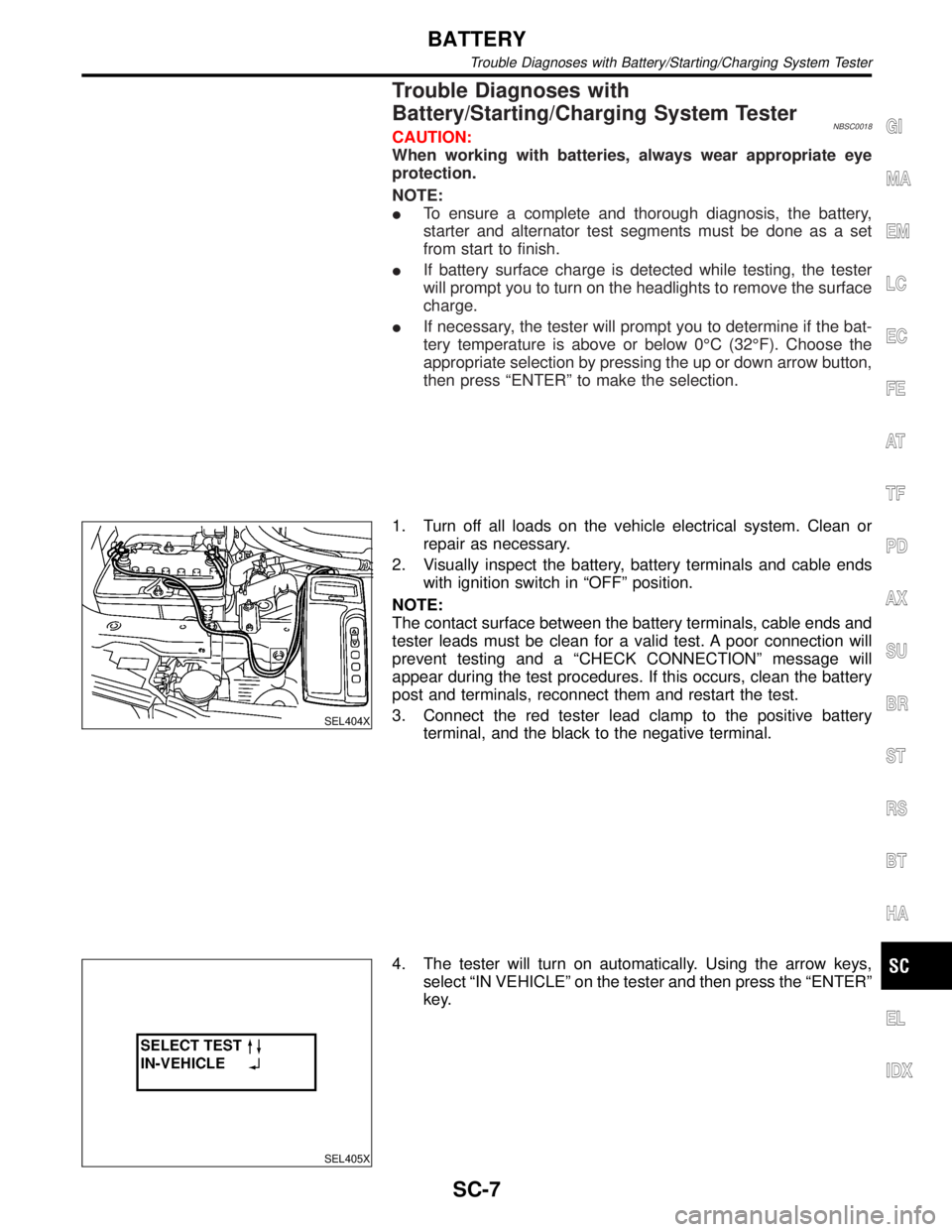
1. Turn off all loads on the vehicle electrical system. Clean or
repair as necessary.
2. Visually inspect the battery, battery terminals and cable ends
with ignition switch in ªOFFº position.
NOTE:
The contact surface between the battery terminals, cable ends and
tester leads must be clean for a valid test. A poor connection will
prevent testing and a ªCHECK CONNECTIONº message will
appear during the test procedures. If this occurs, clean the battery
post and terminals, reconnect them and restart the test.
3. Connect the red tester lead clamp to the positive battery
terminal, and the black to the negative terminal.
SEL405X
4. The tester will turn on automatically. Using the arrow keys,
select ªIN VEHICLEº on the tester and then press the ªENTERº
key.
GI
MA
EM
LC
EC
FE
AT
TF
PD
AX
SU
BR
ST
RS
BT
HA
EL
IDX
BATTERY
Trouble Diagnoses with Battery/Starting/Charging System Tester
SC-7
Page 2161 of 2395
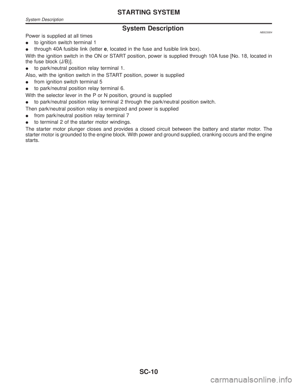
System DescriptionNBSC0004Power is supplied at all times
Ito ignition switch terminal 1
Ithrough 40A fusible link (lettere, located in the fuse and fusible link box).
With the ignition switch in the ON or START position, power is supplied through 10A fuse [No. 18, located in
the fuse block (J/B)].
Ito park/neutral position relay terminal 1.
Also, with the ignition switch in the START position, power is supplied
Ifrom ignition switch terminal 5
Ito park/neutral position relay terminal 6.
With the selector lever in the P or N position, ground is supplied
Ito park/neutral position relay terminal 2 through the park/neutral position switch.
Then park/neutral position relay is energized and power is supplied
Ifrom park/neutral position relay terminal 7
Ito terminal 2 of the starter motor windings.
The starter motor plunger closes and provides a closed circuit between the battery and starter motor. The
starter motor is grounded to the engine block. With power and ground supplied, cranking occurs and the engine
starts.
STARTING SYSTEM
System Description
SC-10
Page 2166 of 2395
DIAGNOSTIC PROCEDURE 1NBSC0019S03Check ªBº Terminal CircuitNBSC0019S0301
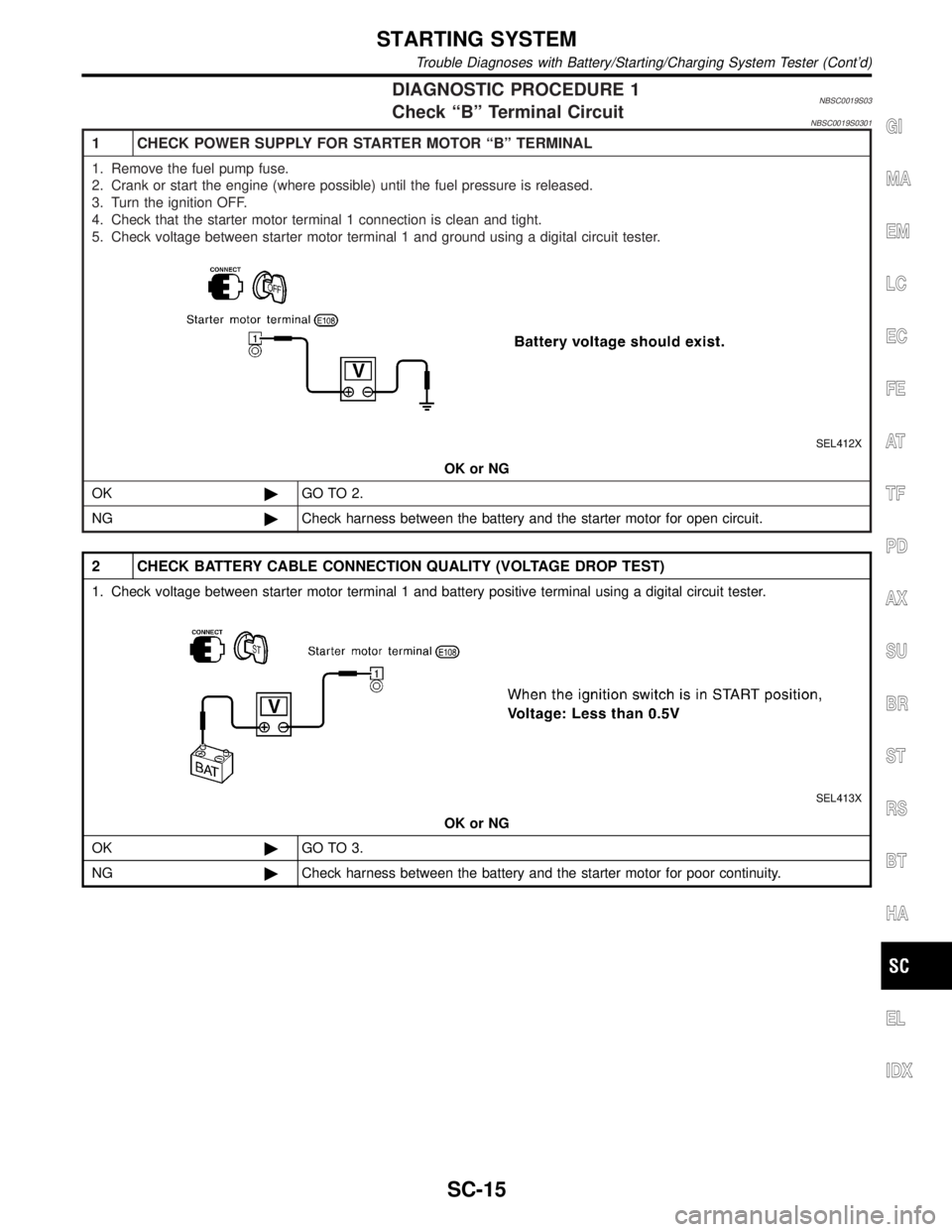
1 CHECK POWER SUPPLY FOR STARTER MOTOR ªBº TERMINAL
1. Remove the fuel pump fuse.
2. Crank or start the engine (where possible) until the fuel pressure is released.
3. Turn the ignition OFF.
4. Check that the starter motor terminal 1 connection is clean and tight.
5. Check voltage between starter motor terminal 1 and ground using a digital circuit tester.
SEL412X
OK or NG
OK©GO TO 2.
NG©Check harness between the battery and the starter motor for open circuit.
2 CHECK BATTERY CABLE CONNECTION QUALITY (VOLTAGE DROP TEST)
1. Check voltage between starter motor terminal 1 and battery positive terminal using a digital circuit tester.
SEL413X
OK or NG
OK©GO TO 3.
NG©Check harness between the battery and the starter motor for poor continuity.
GI
MA
EM
LC
EC
FE
AT
TF
PD
AX
SU
BR
ST
RS
BT
HA
EL
IDX
STARTING SYSTEM
Trouble Diagnoses with Battery/Starting/Charging System Tester (Cont'd)
SC-15
Page 2168 of 2395
DIAGNOSTIC PROCEDURE 2=NBSC0019S04Check ªSº Terminal CircuitNBSC0019S0401
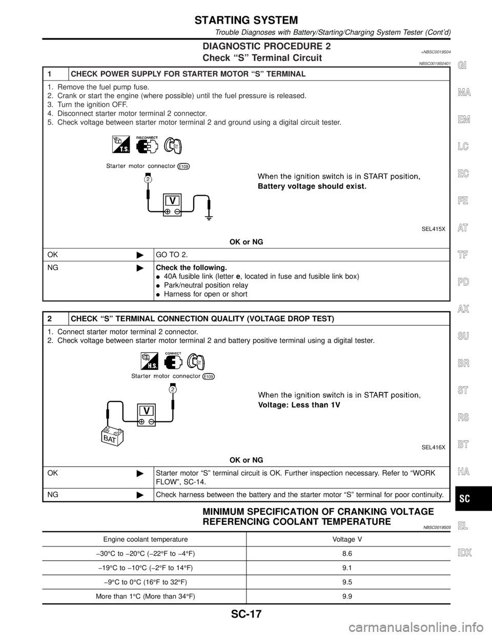
1 CHECK POWER SUPPLY FOR STARTER MOTOR ªSº TERMINAL
1. Remove the fuel pump fuse.
2. Crank or start the engine (where possible) until the fuel pressure is released.
3. Turn the ignition OFF.
4. Disconnect starter motor terminal 2 connector.
5. Check voltage between starter motor terminal 2 and ground using a digital circuit tester.
SEL415X
OK or NG
OK©GO TO 2.
NG©Check the following.
I40A fusible link (lettere, located in fuse and fusible link box)
IPark/neutral position relay
IHarness for open or short
2 CHECK ªSº TERMINAL CONNECTION QUALITY (VOLTAGE DROP TEST)
1. Connect starter motor terminal 2 connector.
2. Check voltage between starter motor terminal 2 and battery positive terminal using a digital tester.
SEL416X
OK or NG
OK©Starter motor ªSº terminal circuit is OK. Further inspection necessary. Refer to ªWORK
FLOWº, SC-14.
NG©Check harness between the battery and the starter motor ªSº terminal for poor continuity.
MINIMUM SPECIFICATION OF CRANKING VOLTAGE
REFERENCING COOLANT TEMPERATURE
NBSC0019S05
Engine coolant temperature Voltage V
þ30ÉC to þ20ÉC (þ22ÉF to þ4ÉF) 8.6
þ19ÉC to þ10ÉC (þ2ÉF to 14ÉF) 9.1
þ9ÉC to 0ÉC (16ÉF to 32ÉF) 9.5
More than 1ÉC (More than 34ÉF) 9.9
GI
MA
EM
LC
EC
FE
AT
TF
PD
AX
SU
BR
ST
RS
BT
HA
EL
IDX
STARTING SYSTEM
Trouble Diagnoses with Battery/Starting/Charging System Tester (Cont'd)
SC-17
Page 2170 of 2395
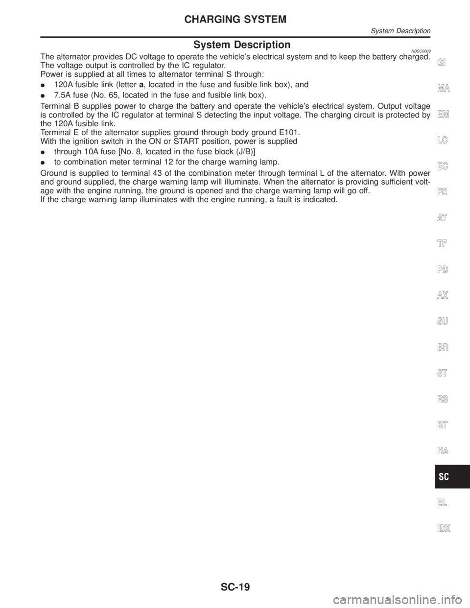
System DescriptionNBSC0009The alternator provides DC voltage to operate the vehicle's electrical system and to keep the battery charged.
The voltage output is controlled by the IC regulator.
Power is supplied at all times to alternator terminal S through:
I120A fusible link (lettera, located in the fuse and fusible link box), and
I7.5A fuse (No. 65, located in the fuse and fusible link box).
Terminal B supplies power to charge the battery and operate the vehicle's electrical system. Output voltage
is controlled by the IC regulator at terminal S detecting the input voltage. The charging circuit is protected by
the 120A fusible link.
Terminal E of the alternator supplies ground through body ground E101.
With the ignition switch in the ON or START position, power is supplied
Ithrough 10A fuse [No. 8, located in the fuse block (J/B)]
Ito combination meter terminal 12 for the charge warning lamp.
Ground is supplied to terminal 43 of the combination meter through terminal L of the alternator. With power
and ground supplied, the charge warning lamp will illuminate. When the alternator is providing sufficient volt-
age with the engine running, the ground is opened and the charge warning lamp will go off.
If the charge warning lamp illuminates with the engine running, a fault is indicated.GI
MA
EM
LC
EC
FE
AT
TF
PD
AX
SU
BR
ST
RS
BT
HA
EL
IDX
CHARGING SYSTEM
System Description
SC-19
Page 2176 of 2395
DIAGNOSTIC PROCEDURE 1NBSC0020S03Check ªLº Terminal CircuitNBSC0020S0301
1 CHECK ªLº TERMINAL CONNECTION
Check to see if ªLº terminal is clean and tight.
OK or NG
OK©GO TO 2.
NG©Repair ªLº terminal connection. Confirm repair by performing complete Battery/Starting/
Charging system test.
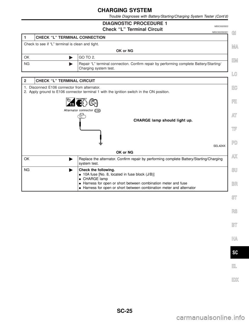
2 CHECK ªLº TERMINAL CIRCUIT
1. Disconnect E106 connector from alternator.
2. Apply ground to E106 connector terminal 1 with the ignition switch in the ON position.
SEL424X
OK or NG
OK©Replace the alternator. Confirm repair by performing complete Battery/Starting/Charging
system test.
NG©Check the following.
I10A fuse [No. 8, located in fuse block (J/B)]
ICHARGE lamp
IHarness for open or short between combination meter and fuse
IHarness for open or short between combination meter and alternator
GI
MA
EM
LC
EC
FE
AT
TF
PD
AX
SU
BR
ST
RS
BT
HA
EL
IDX
CHARGING SYSTEM
Trouble Diagnoses with Battery/Starting/Charging System Tester (Cont'd)
SC-25
Page 2189 of 2395
SST601C
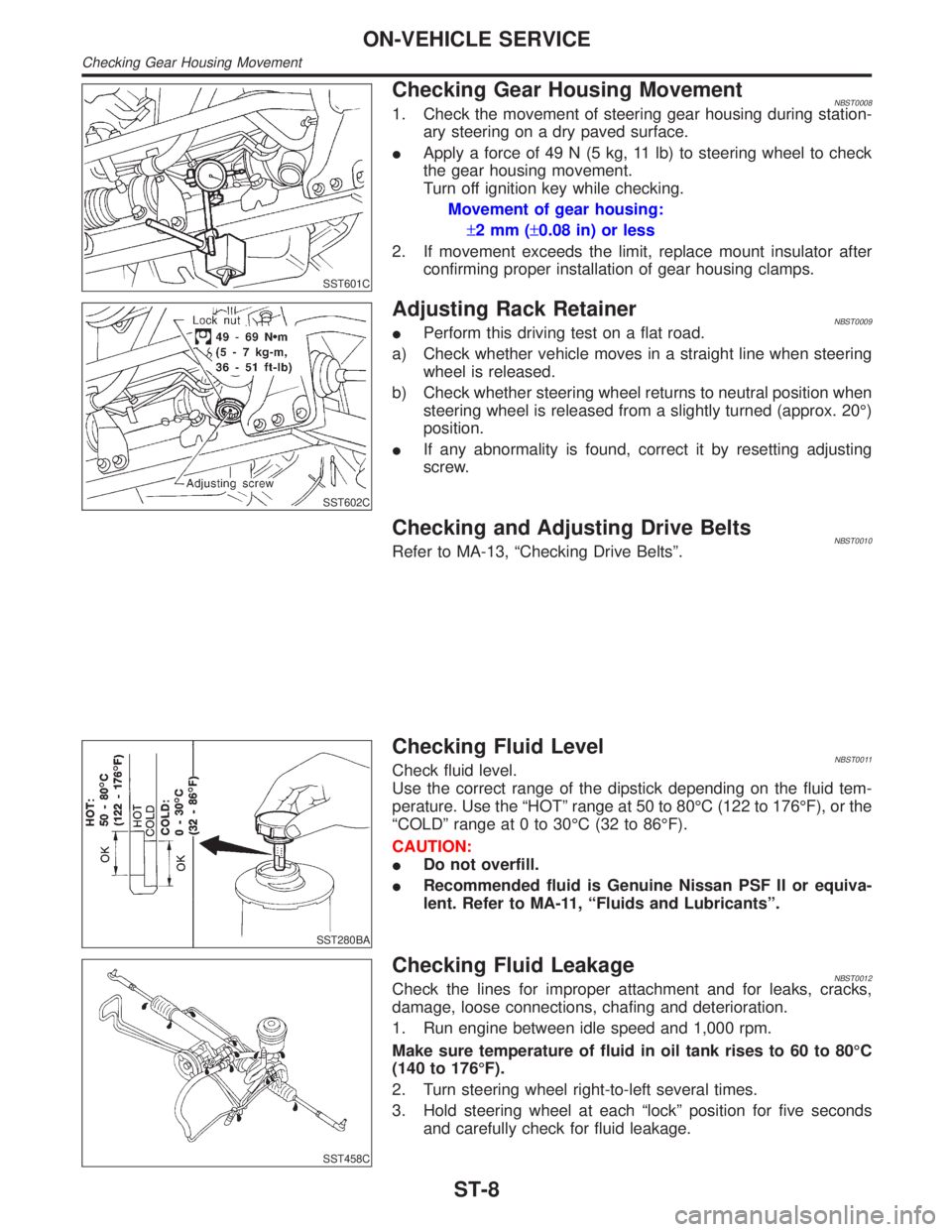
Checking Gear Housing MovementNBST00081. Check the movement of steering gear housing during station-
ary steering on a dry paved surface.
IApply a force of 49 N (5 kg, 11 lb) to steering wheel to check
the gear housing movement.
Turn off ignition key while checking.
Movement of gear housing:
±2mm(±0.08 in) or less
2. If movement exceeds the limit, replace mount insulator after
confirming proper installation of gear housing clamps.
SST602C
Adjusting Rack RetainerNBST0009IPerform this driving test on a flat road.
a) Check whether vehicle moves in a straight line when steering
wheel is released.
b) Check whether steering wheel returns to neutral position when
steering wheel is released from a slightly turned (approx. 20É)
position.
IIf any abnormality is found, correct it by resetting adjusting
screw.
Checking and Adjusting Drive BeltsNBST0010Refer to MA-13, ªChecking Drive Beltsº.
SST280BA
Checking Fluid LevelNBST0011Check fluid level.
Use the correct range of the dipstick depending on the fluid tem-
perature. Use the ªHOTº range at 50 to 80ÉC (122 to 176ÉF), or the
ªCOLDº range at 0 to 30ÉC (32 to 86ÉF).
CAUTION:
IDo not overfill.
IRecommended fluid is Genuine Nissan PSF II or equiva-
lent. Refer to MA-11, ªFluids and Lubricantsº.
SST458C
Checking Fluid LeakageNBST0012Check the lines for improper attachment and for leaks, cracks,
damage, loose connections, chafing and deterioration.
1. Run engine between idle speed and 1,000 rpm.
Make sure temperature of fluid in oil tank rises to 60 to 80ÉC
(140 to 176ÉF).
2. Turn steering wheel right-to-left several times.
3. Hold steering wheel at each ªlockº position for five seconds
and carefully check for fluid leakage.
ON-VEHICLE SERVICE
Checking Gear Housing Movement
ST-8
Page 2238 of 2395
Supplemental Restraint System (SRS) ªAIR
BAGº and ªSEAT BELT PRE-TENSIONERº
NBTF0001The Supplemental Restraint System such as ªAIR BAGº and ªSEAT BELT PRE-TENSIONERº used along with
a seat belt, helps to reduce the risk or severity of injury to the driver and front passenger for certain types of
collision. The SRS system composition which is available to INFINITI QX4 is as follows:
IFor a frontal collision
The Supplemental Restraint System consists of driver air bag module (located in the center of the steer-
ing wheel), front passenger air bag module (located on the instrument panel on passenger side), seat belt
pre-tensioners, a diagnosis sensor unit, warning lamp, wiring harness and spiral cable.
IFor a side collision
The Supplemental Restraint System consists of side air bag module (located in the outer side of front seat),
satellite sensor, diagnosis sensor unit (one of components of air bags for a frontal collision), wiring harness,
warning lamp (one of components of air bags for a frontal collision).
Information necessary to service the system safely is included in theRSsection of this Service Manual.
WARNING:
ITo avoid rendering the SRS inoperative, which could increase the risk of personal injury or death
in the event of a collision which would result in air bag inflation, all maintenance must be performed
by an authorized INFINITI dealer.
IImproper maintenance, including incorrect removal and installation of the SRS, can lead to per-
sonal injury caused by unintentional activation of the system. For removal of Spiral Cable and Air
Bag Module, see the RS section.
IDo not use electrical test equipment on any circuit related to the SRS unless instructed to in this
Service Manual. Spiral cable and wiring harnesses covered with yellow insulation tape either just
before the harness connectors or for the complete harness are related to the SRS.
SEF289H
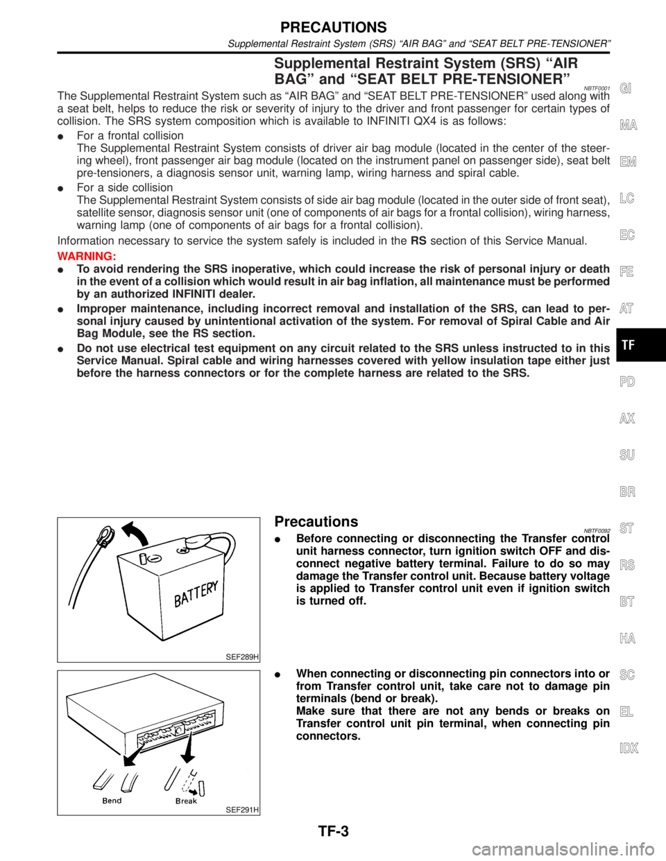
PrecautionsNBTF0092IBefore connecting or disconnecting the Transfer control
unit harness connector, turn ignition switch OFF and dis-
connect negative battery terminal. Failure to do so may
damage the Transfer control unit. Because battery voltage
is applied to Transfer control unit even if ignition switch
is turned off.
SEF291H
IWhen connecting or disconnecting pin connectors into or
from Transfer control unit, take care not to damage pin
terminals (bend or break).
Make sure that there are not any bends or breaks on
Transfer control unit pin terminal, when connecting pin
connectors.
GI
MA
EM
LC
EC
FE
AT
PD
AX
SU
BR
ST
RS
BT
HA
SC
EL
IDX
PRECAUTIONS
Supplemental Restraint System (SRS) ªAIR BAGº and ªSEAT BELT PRE-TENSIONERº
TF-3