Page 1110 of 2395

SEF013Z
11) Make sure the following.
Condition
VENT CONTROL/VAir passage continuity
betweenAandB
ON No
OFF Yes
If the result is NG, go to ªDiagnostic Procedureº, EC-577.
If the result is OK, go to ªDiagnostic Procedureº for DTC
P0440, EC-355.
AEC783A
Overall Function CheckNBEC0343Use this procedure to check the overall function of the EVAP can-
ister vent control valve circuit. During this check, a DTC might not
be confirmed.
WITH GSTNBEC0343S011) Disconnect hose from water separator.
2) Disconnect EVAP canister vent control valve harness connec-
tor.
3) Verify the following.
Condition Air passage continuity
12V direct current supply between ter-
minals 1 and 2No
No supply Yes
If the result is NG, go to ªDiagnostic Procedureº, EC-577.
If the result is OK, go to ªDiagnostic Procedureº for DTC
P0440, EC-355.
GI
MA
EM
LC
FE
AT
TF
PD
AX
SU
BR
ST
RS
BT
HA
SC
EL
IDX
DTC P1448 EVAPORATIVE EMISSION (EVAP) CANISTER VENT CONTROL
VALVE (OPEN)
DTC Confirmation Procedure (Cont'd)
EC-575
Page 1112 of 2395
Diagnostic ProcedureNBEC0345
1 CHECK RUBBER TUBE
1. Turn ignition switch ªOFFº.
2. Disconnect rubber tube connected to EVAP canister vent control valve.
3. Check the rubber tube for clogging.
SEF143S
OK or NG
OK©GO TO 2.
NG©Clean rubber tube using an air blower.
2 CHECK EVAP CANISTER VENT CONTROL VALVE-I
1. Remove EVAP canister vent control valve from EVAP canister.
2. Check portionBof EVAP canister vent control valve for being rusted.
SEF337X
OK or NG
OK©GO TO 3.
NG©Replace EVAP canister vent control valve.
GI
MA
EM
LC
FE
AT
TF
PD
AX
SU
BR
ST
RS
BT
HA
SC
EL
IDX
DTC P1448 EVAPORATIVE EMISSION (EVAP) CANISTER VENT CONTROL
VALVE (OPEN)
Diagnostic Procedure
EC-577
Page 1114 of 2395

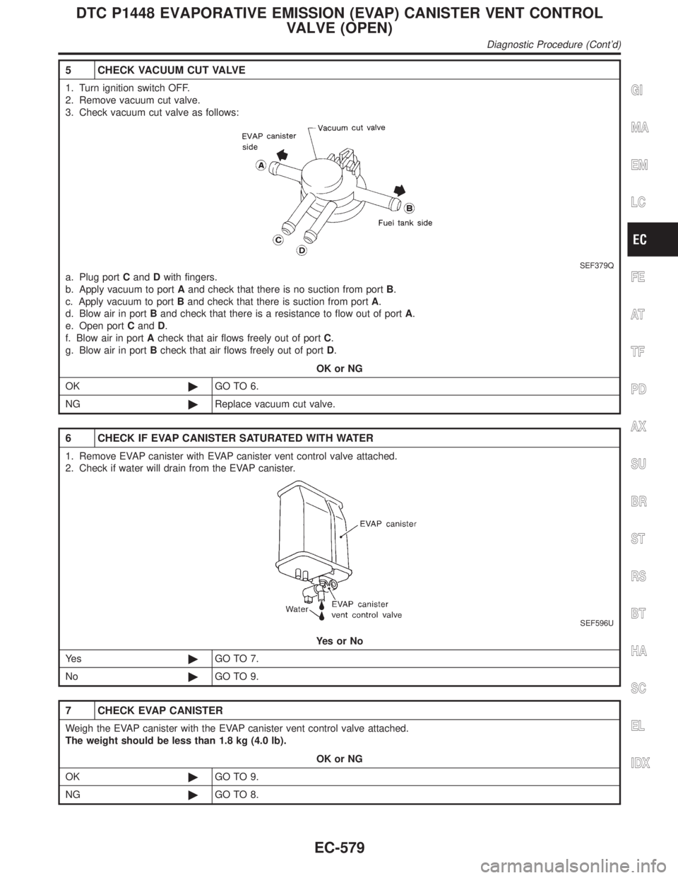
5 CHECK VACUUM CUT VALVE
1. Turn ignition switch OFF.
2. Remove vacuum cut valve.
3. Check vacuum cut valve as follows:
SEF379Q
a. Plug portCandDwith fingers.
b. Apply vacuum to portAand check that there is no suction from portB.
c. Apply vacuum to portBand check that there is suction from portA.
d. Blow air in portBand check that there is a resistance to flow out of portA.
e. Open portCandD.
f. Blow air in portAcheck that air flows freely out of portC.
g. Blow air in portBcheck that air flows freely out of portD.
OK or NG
OK©GO TO 6.
NG©Replace vacuum cut valve.
6 CHECK IF EVAP CANISTER SATURATED WITH WATER
1. Remove EVAP canister with EVAP canister vent control valve attached.
2. Check if water will drain from the EVAP canister.
SEF596U
YesorNo
Ye s©GO TO 7.
No©GO TO 9.
7 CHECK EVAP CANISTER
Weigh the EVAP canister with the EVAP canister vent control valve attached.
The weight should be less than 1.8 kg (4.0 lb).
OK or NG
OK©GO TO 9.
NG©GO TO 8.
GI
MA
EM
LC
FE
AT
TF
PD
AX
SU
BR
ST
RS
BT
HA
SC
EL
IDX
DTC P1448 EVAPORATIVE EMISSION (EVAP) CANISTER VENT CONTROL
VALVE (OPEN)
Diagnostic Procedure (Cont'd)
EC-579
Page 1116 of 2395

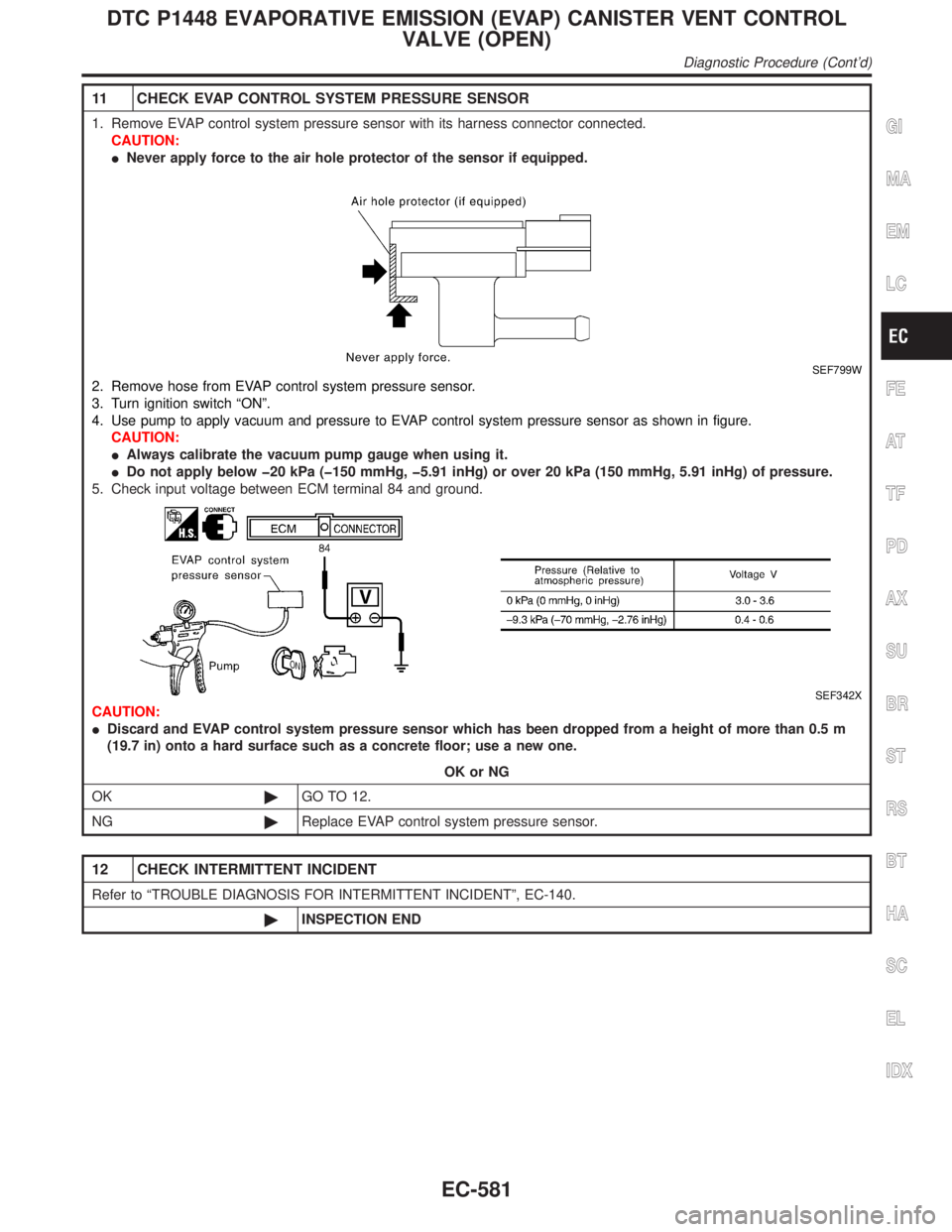
11 CHECK EVAP CONTROL SYSTEM PRESSURE SENSOR
1. Remove EVAP control system pressure sensor with its harness connector connected.
CAUTION:
INever apply force to the air hole protector of the sensor if equipped.
SEF799W
2. Remove hose from EVAP control system pressure sensor.
3. Turn ignition switch ªONº.
4. Use pump to apply vacuum and pressure to EVAP control system pressure sensor as shown in figure.
CAUTION:
IAlways calibrate the vacuum pump gauge when using it.
IDo not apply below þ20 kPa (þ150 mmHg, þ5.91 inHg) or over 20 kPa (150 mmHg, 5.91 inHg) of pressure.
5. Check input voltage between ECM terminal 84 and ground.
SEF342X
CAUTION:
IDiscard and EVAP control system pressure sensor which has been dropped from a height of more than 0.5 m
(19.7 in) onto a hard surface such as a concrete floor; use a new one.
OK or NG
OK©GO TO 12.
NG©Replace EVAP control system pressure sensor.
12 CHECK INTERMITTENT INCIDENT
Refer to ªTROUBLE DIAGNOSIS FOR INTERMITTENT INCIDENTº, EC-140.
©INSPECTION END
GI
MA
EM
LC
FE
AT
TF
PD
AX
SU
BR
ST
RS
BT
HA
SC
EL
IDX
DTC P1448 EVAPORATIVE EMISSION (EVAP) CANISTER VENT CONTROL
VALVE (OPEN)
Diagnostic Procedure (Cont'd)
EC-581
Page 1118 of 2395
Wiring DiagramNBEC0640
MEC985C
GI
MA
EM
LC
FE
AT
TF
PD
AX
SU
BR
ST
RS
BT
HA
SC
EL
IDX
DTC P1464 FUEL LEVEL SENSOR CIRCUIT (GROUND SIGNAL)
Wiring Diagram
EC-583
Page 1120 of 2395

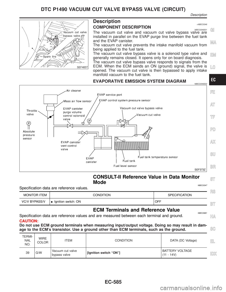
SEF485T
Description=NBEC0346COMPONENT DESCRIPTIONNBEC0346S01The vacuum cut valve and vacuum cut valve bypass valve are
installed in parallel on the EVAP purge line between the fuel tank
and the EVAP canister.
The vacuum cut valve prevents the intake manifold vacuum from
being applied to the fuel tank.
The vacuum cut valve bypass valve is a solenoid type valve and
generally remains closed. It opens only for on board diagnosis.
The vacuum cut valve bypass valve responds to signals from the
ECM. When the ECM sends an ON (ground) signal, the valve is
opened. The vacuum cut valve is then bypassed to apply intake
manifold vacuum to the fuel tank.
EVAPORATIVE EMISSION SYSTEM DIAGRAMNBEC0346S02
SEF373Z
CONSULT-II Reference Value in Data Monitor
Mode
NBEC0347Specification data are reference values.
MONITOR ITEM CONDITION SPECIFICATION
VC/V BYPASS/VIIgnition switch: ON OFF
ECM Terminals and Reference ValueNBEC0681Specification data are reference values and are measured between each terminal and ground.
CAUTION:
Do not use ECM ground terminals when measuring input/output voltage. Doing so may result in dam-
age to the ECM's transistor. Use a ground other than ECM terminals, such as the ground.
TERMI-
NAL
NO.WIRE
COLORITEM CONDITION DATA (DC Voltage)
39 G/WVacuum cut valve
bypass valve[Ignition switch ªONº]BATTERY VOLTAGE
(11 - 14V)
GI
MA
EM
LC
FE
AT
TF
PD
AX
SU
BR
ST
RS
BT
HA
SC
EL
IDX
DTC P1490 VACUUM CUT VALVE BYPASS VALVE (CIRCUIT)
Description
EC-585
Page 1122 of 2395
Wiring DiagramNBEC0351
MEC972C
GI
MA
EM
LC
FE
AT
TF
PD
AX
SU
BR
ST
RS
BT
HA
SC
EL
IDX
DTC P1490 VACUUM CUT VALVE BYPASS VALVE (CIRCUIT)
Wiring Diagram
EC-587
Page 1124 of 2395

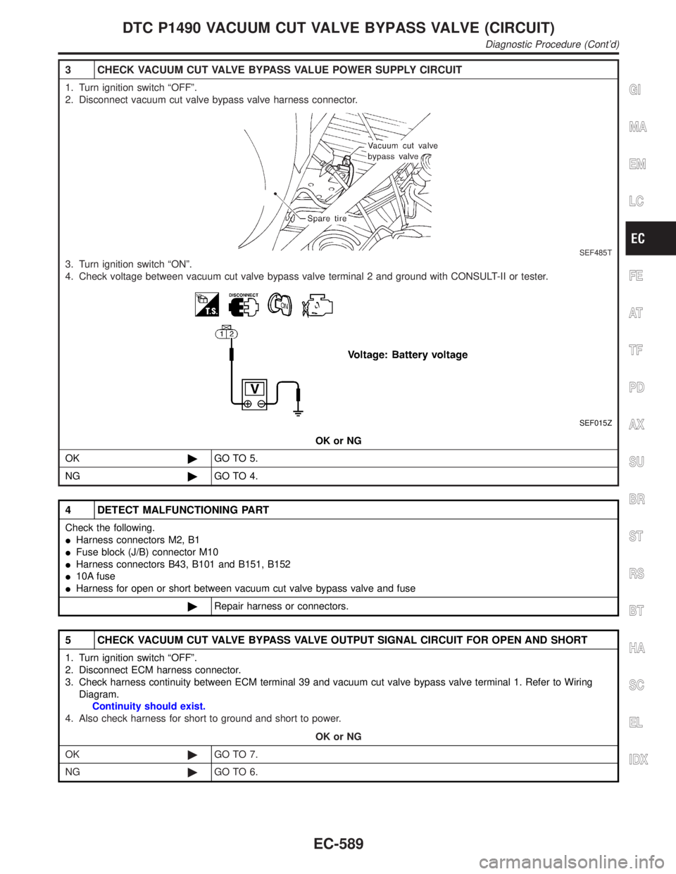
3 CHECK VACUUM CUT VALVE BYPASS VALUE POWER SUPPLY CIRCUIT
1. Turn ignition switch ªOFFº.
2. Disconnect vacuum cut valve bypass valve harness connector.
SEF485T
3. Turn ignition switch ªONº.
4. Check voltage between vacuum cut valve bypass valve terminal 2 and ground with CONSULT-II or tester.
SEF015Z
OK or NG
OK©GO TO 5.
NG©GO TO 4.
4 DETECT MALFUNCTIONING PART
Check the following.
IHarness connectors M2, B1
IFuse block (J/B) connector M10
IHarness connectors B43, B101 and B151, B152
I10A fuse
IHarness for open or short between vacuum cut valve bypass valve and fuse
©Repair harness or connectors.
5 CHECK VACUUM CUT VALVE BYPASS VALVE OUTPUT SIGNAL CIRCUIT FOR OPEN AND SHORT
1. Turn ignition switch ªOFFº.
2. Disconnect ECM harness connector.
3. Check harness continuity between ECM terminal 39 and vacuum cut valve bypass valve terminal 1. Refer to Wiring
Diagram.
Continuity should exist.
4. Also check harness for short to ground and short to power.
OK or NG
OK©GO TO 7.
NG©GO TO 6.
GI
MA
EM
LC
FE
AT
TF
PD
AX
SU
BR
ST
RS
BT
HA
SC
EL
IDX
DTC P1490 VACUUM CUT VALVE BYPASS VALVE (CIRCUIT)
Diagnostic Procedure (Cont'd)
EC-589