Page 1142 of 2395
Wiring DiagramNBEC0373
MEC973C
GI
MA
EM
LC
FE
AT
TF
PD
AX
SU
BR
ST
RS
BT
HA
SC
EL
IDX
DTC P1706 PARK/NEUTRAL POSITION (PNP) SWITCH
Wiring Diagram
EC-607
Page 1144 of 2395
6 CHECK INTERMITTENT INCIDENT
Refer to ªTROUBLE DIGNOSIS FOR INTERMITTENT INCIDENTº, EC-140.
©INSPECTION ENDGI
MA
EM
LC
FE
AT
TF
PD
AX
SU
BR
ST
RS
BT
HA
SC
EL
IDX
DTC P1706 PARK/NEUTRAL POSITION (PNP) SWITCH
Diagnostic Procedure (Cont'd)
EC-609
Page 1146 of 2395

SEF018Z
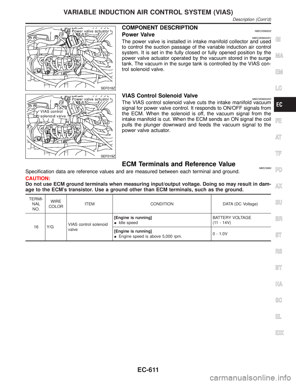
COMPONENT DESCRIPTIONNBEC0596S02Power ValveNBEC0596S0201The power valve is installed in intake manifold collector and used
to control the suction passage of the variable induction air control
system. It is set in the fully closed or fully opened position by the
power valve actuator operated by the vacuum stored in the surge
tank. The vacuum in the surge tank is controlled by the VIAS con-
trol solenoid valve.
SEF019Z
VIAS Control Solenoid ValveNBEC0596S0202The VIAS control solenoid valve cuts the intake manifold vacuum
signal for power valve control. It responds to ON/OFF signals from
the ECM. When the solenoid is off, the vacuum signal from the
intake manifold is cut. When the ECM sends an ON signal the coil
pulls the plunger downward and feeds the vacuum signal to the
power valve actuator.
ECM Terminals and Reference ValueNBEC0684Specification data are reference values and are measured between each terminal and ground.
CAUTION:
Do not use ECM ground terminals when measuring input/output voltage. Doing so may result in dam-
age to the ECM's transistor. Use a ground other than ECM terminals, such as the ground.
TERMI-
NAL
NO.WIRE
COLORITEM CONDITION DATA (DC Voltage)
16 Y/GVIAS control solenoid
valve[Engine is running]
IIdle speedBATTERY VOLTAGE
(11 - 14V)
[Engine is running]
IEngine speed is above 5,000 rpm.0 - 1.0V
GI
MA
EM
LC
FE
AT
TF
PD
AX
SU
BR
ST
RS
BT
HA
SC
EL
IDX
VARIABLE INDUCTION AIR CONTROL SYSTEM (VIAS)
Description (Cont'd)
EC-611
Page 1148 of 2395
Diagnostic ProcedureNBEC0598
1 CHECK OVERALL FUNCTION
With CONSULT-II
1. Start engine and warm it up to normal operating temperature.
2. Perform ªVIAS SOL VALVEº in ªACTIVE TESTº mode with CONSULT-II.
3. Turn VIAS control solenoid valve ªONº and ªOFFº, and make sure that power valve actuator rod moves.
SEC304C
Without CONSULT-II
1. Start engine and warm it up to normal operating temperature.
2. Rev engine quickly up to above 5,000 rpm and make sure that power valve actuator rod moves.
SEF021Z
OK or NG
OK©INSPECTION END
NG©GO TO 2.
GI
MA
EM
LC
FE
AT
TF
PD
AX
SU
BR
ST
RS
BT
HA
SC
EL
IDX
VARIABLE INDUCTION AIR CONTROL SYSTEM (VIAS)
Diagnostic Procedure
EC-613
Page 1150 of 2395
5 RETEST OVERALL FUNCTION
1. Reconnect harness connectors disconnected.
2. Perform Test No. 1 again.
OK or NG
OK©INSPECTION END
NG©GO TO 6.
6 CHECK INTERMITTENT INCIDENT
Refer to ªTROUBLE DIAGNOSIS FOR INTERMITTENT INCIDENTº, EC-140.
OK or NG
OK©Replace VIAS control solenoid valve as intake manifold collector assembly.
NG©Repair or replace harness or connectors.
GI
MA
EM
LC
FE
AT
TF
PD
AX
SU
BR
ST
RS
BT
HA
SC
EL
IDX
VARIABLE INDUCTION AIR CONTROL SYSTEM (VIAS)
Diagnostic Procedure (Cont'd)
EC-615
Page 1152 of 2395
Wiring DiagramNBEC0386
MEC974C
GI
MA
EM
LC
FE
AT
TF
PD
AX
SU
BR
ST
RS
BT
HA
SC
EL
IDX
INJECTOR
Wiring Diagram
EC-617
Page 1154 of 2395
3 CHECK INJECTOR POWER SUPPLY CIRCUIT
1. Turn ignition switch ªOFFº.
SEF023Z
2. Turn ignition switch ªONº.
3. Check voltage between injector terminal 1 and ground with CONSULT-II or tester.
SEF364Z
OK or NG
OK©GO TO 5.
NG©GO TO 4.
4 DETECT MALFUNCTIONING PART
Check the following.
IHarness connectors M33, F22
IHarness connectors F5, F100
IFuse block (J/B) connector M10
I10A fuse
IHarness for open or short between injector and fuse
©Repair harness or connectors.
5 CHECK INJECTOR OUTPUT SIGNAL CIRCUIT FOR OPEN AND SHORT
1. Turn ignition switch ªOFFº.
2. Disconnect ECM harness connector.
3. Check harness continuity between injector terminal 2 and ECM terminals 103, 104, 107, 101, 105, 102. Refer to Wiring
Diagram.
Continuity should exist.
4. Also check harness for short to ground and short to power.
OK or NG
OK©GO TO 7.
NG©GO TO 6.
GI
MA
EM
LC
FE
AT
TF
PD
AX
SU
BR
ST
RS
BT
HA
SC
EL
IDX
INJECTOR
Diagnostic Procedure (Cont'd)
EC-619
Page 1156 of 2395
CONSULT-II Reference Value in Data Monitor
Mode
NBEC0388Specification data are reference values.
MONITOR ITEM CONDITION SPECIFICATION
START SIGNALIIgnition switch: ON,START,ON OFF,ON,OFF
ECM Terminals and Reference ValueNBEC0688Specification data are reference values and are measured between each terminal and ground.
CAUTION:
Do not use ECM ground terminals when measuring input/output voltage. Doing so may result in dam-
age to the ECM's transistor. Use a ground other than ECM terminals, such as the ground.
TERMI-
NAL
NO.WIRE
COLORITEM CONDITION DATA (DC Voltage)
42 B/Y Start signal[Ignition switch ªONº]Approximately 0V
[Ignition switch ªSTARTº]9 - 12V
GI
MA
EM
LC
FE
AT
TF
PD
AX
SU
BR
ST
RS
BT
HA
SC
EL
IDX
START SIGNAL
CONSULT-II Reference Value in Data Monitor Mode
EC-621