Page 2388 of 2395
SMT989C
5. Align claw of oil gutter with center case, and install it.
6. Install front case assembly and rear case assembly.
Refer to ªFinal Assemblyº, TF-153.
SMT891C
Final AssemblyNBTF00841. Install C-rings to mainshaft rear bearing.
SMT889C
2. Check speedometer drive gear teeth for abnormal wear. Set
speedometer drive gear properly on mainshaft, and secure it
with snap ring.
IDo not reuse snap ring.
SMT893C
3. Apply sealing fluid 518 (Locktite) to the entire center case
mounting surface of front case as shown in the figure.
CAUTION:
Remove all foreign materials such as water, oil and grease
from center case and front case mating surfaces.
GI
MA
EM
LC
EC
FE
AT
PD
AX
SU
BR
ST
RS
BT
HA
SC
EL
IDX
ASSEMBLY
Center Case (Cont'd)
TF-153
Page 2390 of 2395

SMT881C
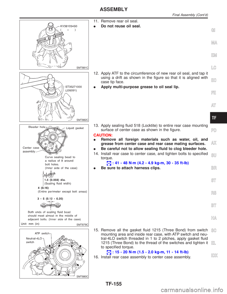
11. Remove rear oil seal.
IDo not reuse oil seal.
SMT882C
12. Apply ATF to the circumference of new rear oil seal, and tap it
using a drift as shown in the figure so that it is aligned with
case tip face.
IApply multi-purpose grease to oil seal lip.
SMT879C
13. Apply sealing fluid 518 (Locktite) to entire rear case mounting
surface of center case as shown in the figure.
CAUTION:
IRemove all foreign materials such as water, oil, and
grease from center case and rear case mating surfaces.
IBe careful not to allow sealing fluid to clog bleeder hole.
14. Install rear case to center case, and tighten bolts to specified
torque.
: 41 - 48 N´m (4.2 - 4.9 kg-m, 30 - 35 ft-lb)
IBe sure to attach harness clips.
SMT880C
15. Remove all the gasket fluid 1215 (Three Bond) from switch
mounting area and inside rear case, with ATP switch and neu-
tral-4LO switch threaded in 1 to 2 pitches, apply gasket fluid
1215 (Three Bond) to the thread of the switches and tighten it
to specified torque.
: 15 - 20 N´m (1.5 - 2.0 kg-m, 11 - 14 ft-lb)
16. Install rear case assembly to center case assembly.
GI
MA
EM
LC
EC
FE
AT
PD
AX
SU
BR
ST
RS
BT
HA
SC
EL
IDX
ASSEMBLY
Final Assembly (Cont'd)
TF-155
Page 2392 of 2395

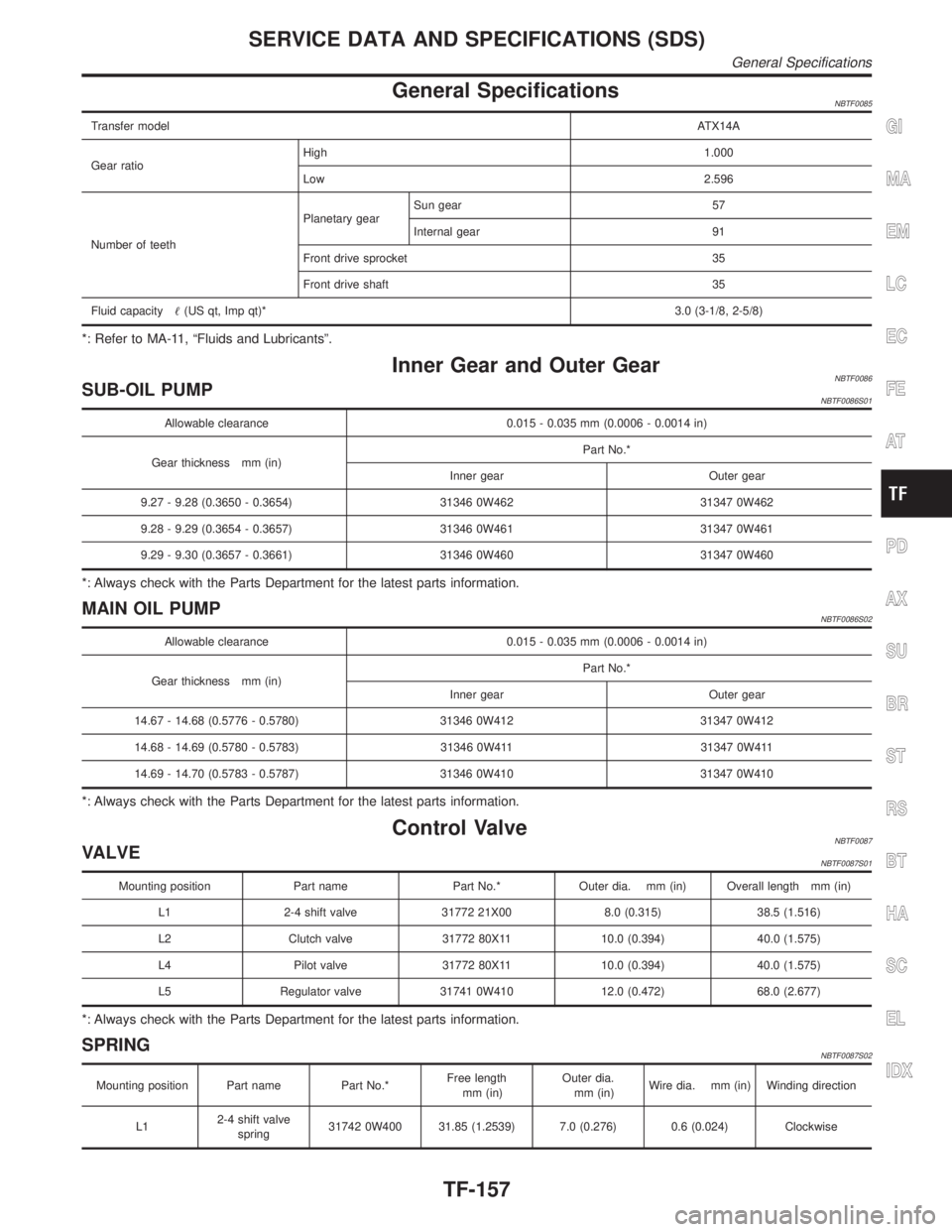
General SpecificationsNBTF0085
Transfer modelATX14A
Gear ratioHigh1.000
Low2.596
Number of teethPlanetary gearSun gear 57
Internal gear 91
Front drive sprocket 35
Front drive shaft 35
Fluid capacity(US qt, Imp qt)*3.0 (3-1/8, 2-5/8)
*: Refer to MA-11, ªFluids and Lubricantsº.
Inner Gear and Outer GearNBTF0086SUB-OIL PUMPNBTF0086S01
Allowable clearance 0.015 - 0.035 mm (0.0006 - 0.0014 in)
Gear thickness mm (in)Part No.*
Inner gear Outer gear
9.27 - 9.28 (0.3650 - 0.3654) 31346 0W462 31347 0W462
9.28 - 9.29 (0.3654 - 0.3657) 31346 0W461 31347 0W461
9.29 - 9.30 (0.3657 - 0.3661) 31346 0W460 31347 0W460
*: Always check with the Parts Department for the latest parts information.
MAIN OIL PUMPNBTF0086S02
Allowable clearance 0.015 - 0.035 mm (0.0006 - 0.0014 in)
Gear thickness mm (in)Part No.*
Inner gear Outer gear
14.67 - 14.68 (0.5776 - 0.5780) 31346 0W412 31347 0W412
14.68 - 14.69 (0.5780 - 0.5783) 31346 0W411 31347 0W411
14.69 - 14.70 (0.5783 - 0.5787) 31346 0W410 31347 0W410
*: Always check with the Parts Department for the latest parts information.
Control ValveNBTF0087VALVENBTF0087S01
Mounting position Part name Part No.* Outer dia. mm (in) Overall length mm (in)
L1 2-4 shift valve 31772 21X00 8.0 (0.315) 38.5 (1.516)
L2 Clutch valve 31772 80X11 10.0 (0.394) 40.0 (1.575)
L4 Pilot valve 31772 80X11 10.0 (0.394) 40.0 (1.575)
L5 Regulator valve 31741 0W410 12.0 (0.472) 68.0 (2.677)
*: Always check with the Parts Department for the latest parts information.
SPRINGNBTF0087S02
Mounting position Part name Part No.*Free length
mm (in)Outer dia.
mm (in)Wire dia. mm (in) Winding direction
L12-4 shift valve
spring31742 0W400 31.85 (1.2539) 7.0 (0.276) 0.6 (0.024) Clockwise
GI
MA
EM
LC
EC
FE
AT
PD
AX
SU
BR
ST
RS
BT
HA
SC
EL
IDX
SERVICE DATA AND SPECIFICATIONS (SDS)
General Specifications
TF-157
Page 2394 of 2395

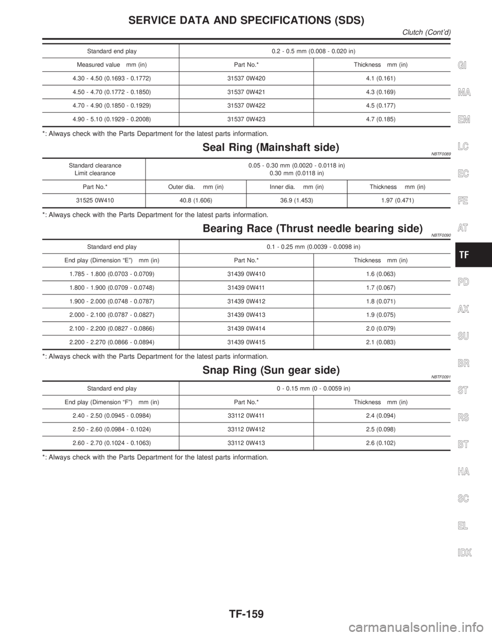
Standard end play 0.2 - 0.5 mm (0.008 - 0.020 in)
Measured value mm (in) Part No.* Thickness mm (in)
4.30 - 4.50 (0.1693 - 0.1772) 31537 0W420 4.1 (0.161)
4.50 - 4.70 (0.1772 - 0.1850) 31537 0W421 4.3 (0.169)
4.70 - 4.90 (0.1850 - 0.1929) 31537 0W422 4.5 (0.177)
4.90 - 5.10 (0.1929 - 0.2008) 31537 0W423 4.7 (0.185)
*: Always check with the Parts Department for the latest parts information.
Seal Ring (Mainshaft side)NBTF0089
Standard clearance
Limit clearance0.05 - 0.30 mm (0.0020 - 0.0118 in)
0.30 mm (0.0118 in)
Part No.* Outer dia. mm (in) Inner dia. mm (in) Thickness mm (in)
31525 0W410 40.8 (1.606) 36.9 (1.453) 1.97 (0.471)
*: Always check with the Parts Department for the latest parts information.
Bearing Race (Thrust needle bearing side)NBTF0090
Standard end play 0.1 - 0.25 mm (0.0039 - 0.0098 in)
End play (Dimension ªEº) mm (in) Part No.* Thickness mm (in)
1.785 - 1.800 (0.0703 - 0.0709) 31439 0W410 1.6 (0.063)
1.800 - 1.900 (0.0709 - 0.0748) 31439 0W411 1.7 (0.067)
1.900 - 2.000 (0.0748 - 0.0787) 31439 0W412 1.8 (0.071)
2.000 - 2.100 (0.0787 - 0.0827) 31439 0W413 1.9 (0.075)
2.100 - 2.200 (0.0827 - 0.0866) 31439 0W414 2.0 (0.079)
2.200 - 2.270 (0.0866 - 0.0894) 31439 0W415 2.1 (0.083)
*: Always check with the Parts Department for the latest parts information.
Snap Ring (Sun gear side)NBTF0091
Standard end play 0 - 0.15 mm (0 - 0.0059 in)
End play (Dimension ªFº) mm (in) Part No.* Thickness mm (in)
2.40 - 2.50 (0.0945 - 0.0984) 33112 0W411 2.4 (0.094)
2.50 - 2.60 (0.0984 - 0.1024) 33112 0W412 2.5 (0.098)
2.60 - 2.70 (0.1024 - 0.1063) 33112 0W413 2.6 (0.102)
*: Always check with the Parts Department for the latest parts information.
GI
MA
EM
LC
EC
FE
AT
PD
AX
SU
BR
ST
RS
BT
HA
SC
EL
IDX
SERVICE DATA AND SPECIFICATIONS (SDS)
Clutch (Cont'd)
TF-159