Page 2372 of 2395
SMT006D
Front Case
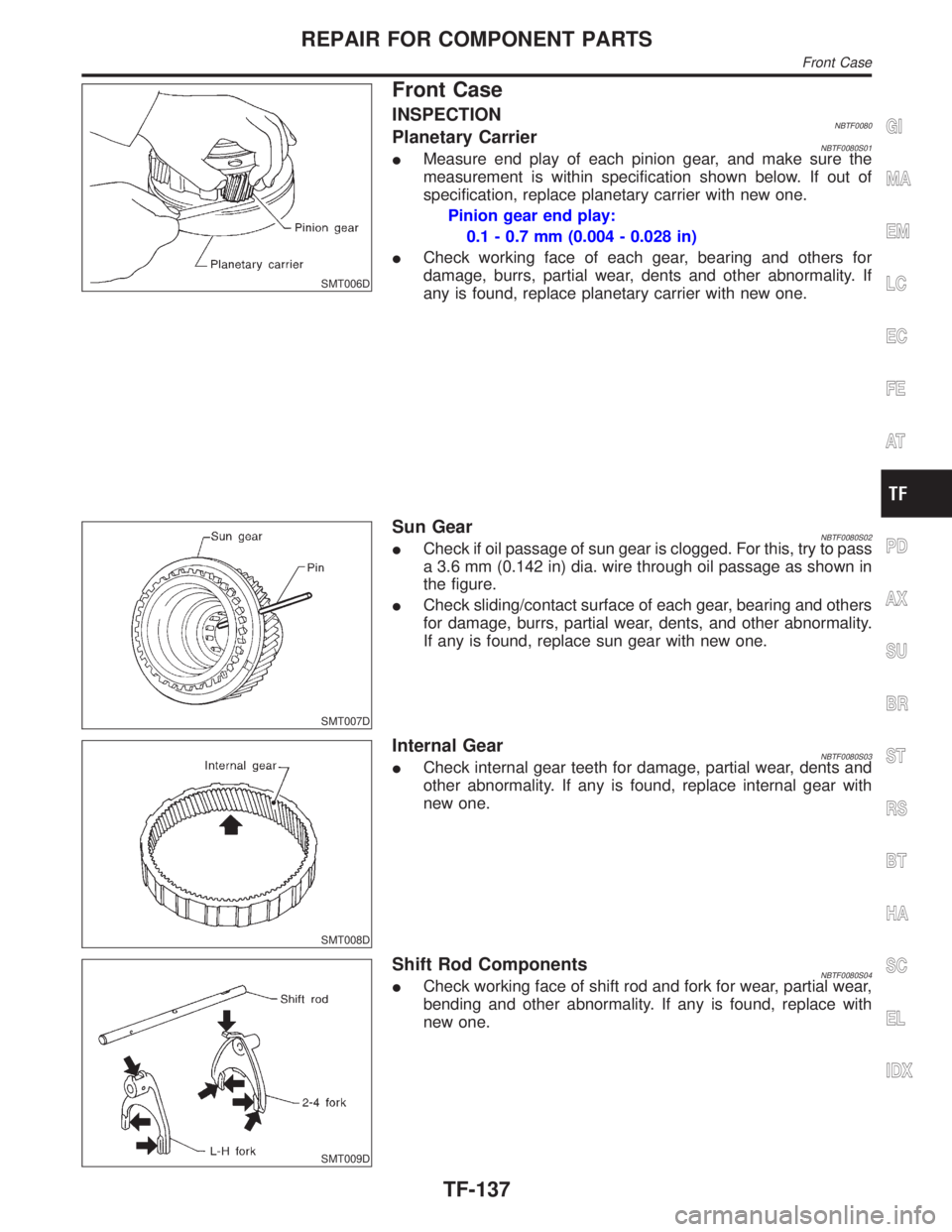
INSPECTIONNBTF0080Planetary CarrierNBTF0080S01IMeasure end play of each pinion gear, and make sure the
measurement is within specification shown below. If out of
specification, replace planetary carrier with new one.
Pinion gear end play:
0.1 - 0.7 mm (0.004 - 0.028 in)
ICheck working face of each gear, bearing and others for
damage, burrs, partial wear, dents and other abnormality. If
any is found, replace planetary carrier with new one.
SMT007D
Sun GearNBTF0080S02ICheck if oil passage of sun gear is clogged. For this, try to pass
a 3.6 mm (0.142 in) dia. wire through oil passage as shown in
the figure.
ICheck sliding/contact surface of each gear, bearing and others
for damage, burrs, partial wear, dents, and other abnormality.
If any is found, replace sun gear with new one.
SMT008D
Internal GearNBTF0080S03ICheck internal gear teeth for damage, partial wear, dents and
other abnormality. If any is found, replace internal gear with
new one.
SMT009D
Shift Rod ComponentsNBTF0080S04ICheck working face of shift rod and fork for wear, partial wear,
bending and other abnormality. If any is found, replace with
new one.
GI
MA
EM
LC
EC
FE
AT
PD
AX
SU
BR
ST
RS
BT
HA
SC
EL
IDX
REPAIR FOR COMPONENT PARTS
Front Case
TF-137
Page 2374 of 2395
SMT945C
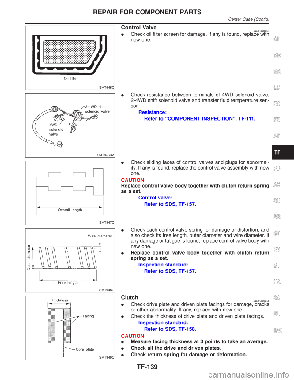
Control ValveNBTF0081S04ICheck oil filter screen for damage. If any is found, replace with
new one.
SMT946CA
ICheck resistance between terminals of 4WD solenoid valve,
2-4WD shift solenoid valve and transfer fluid temperature sen-
sor.
Resistance:
Refer to ªCOMPONENT INSPECTIONº, TF-111.
SMT947C
ICheck sliding faces of control valves and plugs for abnormal-
ity. If any is found, replace the control valve assembly with new
one.
CAUTION:
Replace control valve body together with clutch return spring
as a set.
Control valve:
Refer to SDS, TF-157.
SMT948C
ICheck each control valve spring for damage or distortion, and
also check its free length, outer diameter and wire diameter. If
any damage or fatigue is found, replace control valve body with
new one.
IReplace control valve body together with clutch return
spring as a set.
Inspection standard:
Refer to SDS, TF-157.
SMT949C
ClutchNBTF0081S05ICheck drive plate and driven plate facings for damage, cracks
or other abnormality. If any, replace with new one.
ICheck the thickness of drive plate and driven plate facings.
Inspection standard:
Refer to SDS, TF-158.
CAUTION:
IMeasure facing thickness at 3 points to take an average.
ICheck all the drive and driven plates.
ICheck return spring for damage or deformation.
GI
MA
EM
LC
EC
FE
AT
PD
AX
SU
BR
ST
RS
BT
HA
SC
EL
IDX
REPAIR FOR COMPONENT PARTS
Center Case (Cont'd)
TF-139
Page 2376 of 2395
SMT011D
Front Case
ASSEMBLYNBTF0082Planetary Carrier, Sun Gear and Internal GearNBTF0082S011. Apply ATF to oil seal periphery, and install oil seal so that it is
flush with the end face of front case.
IDo not reuse oil seal.
SMT012D
2. Install internal gear with its groove facing snap ring into front
case. Then secure it with snap ring.
IDo not reuse snap ring.
SMT108D
3. Remove all the liquid gasket on plug bolt and front case. Apply
locking sealant to plug bolt, install it to front case and tighten
it to specified torque.
IWith one crest of plug bolt inserted in the hole, apply liquid
gasket 1215 to the thread.
: 19 - 25 N´m (1.9 - 2.5 kg-m, 14 - 18 ft-lb)
SMT014D
4. Install snap ring to main gear bearing.
IDo not reuse snap rings.
SMT015D
5. Set main gear bearing to front case, then press it.
GI
MA
EM
LC
EC
FE
AT
PD
AX
SU
BR
ST
RS
BT
HA
SC
EL
IDX
ASSEMBLY
Front Case
TF-141
Page 2378 of 2395
SMT021D
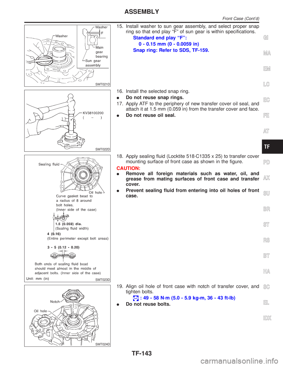
15. Install washer to sun gear assembly, and select proper snap
ring so that end play ªFº of sun gear is within specifications.
Standard end play ªFº:
0 - 0.15 mm (0 - 0.0059 in)
Snap ring: Refer to SDS, TF-159.
SMT022D
16. Install the selected snap ring.
IDo not reuse snap rings.
17. Apply ATF to the periphery of new transfer cover oil seal, and
attach it at 1.5 mm (0.059 in) from the transfer cover and face.
IDo not reuse oil seal.
SMT023D
18. Apply sealing fluid (Locktite 518´C1335 x 25) to transfer cover
mounting surface of front case as shown in the figure.
CAUTION:
IRemove all foreign materials such as water, oil, and
grease from mating surfaces of front case and transfer
cover.
IPrevent sealing fluid from entering into oil holes of front
case.
SMT024D
19. Align oil hole of front case with notch of transfer cover, and
tighten bolts.
: 49 - 58 N´m (5.0 - 5.9 kg-m, 36 - 43 ft-lb)
IDo not reuse bolts.
GI
MA
EM
LC
EC
FE
AT
PD
AX
SU
BR
ST
RS
BT
HA
SC
EL
IDX
ASSEMBLY
Front Case (Cont'd)
TF-143
Page 2380 of 2395
: 15 - 20 N´m (1.5 - 2.0 kg-m, 11 - 14 ft-lb)
IWait detection switch harness connector is black.
6. Install center case assembly to front case assembly. Refer to
ªFinal Assemblyº, TF-153.
7. Install rear case assembly to center case. Refer to ªFinal
Assemblyº, TF-153.
SMT951C
Center Case
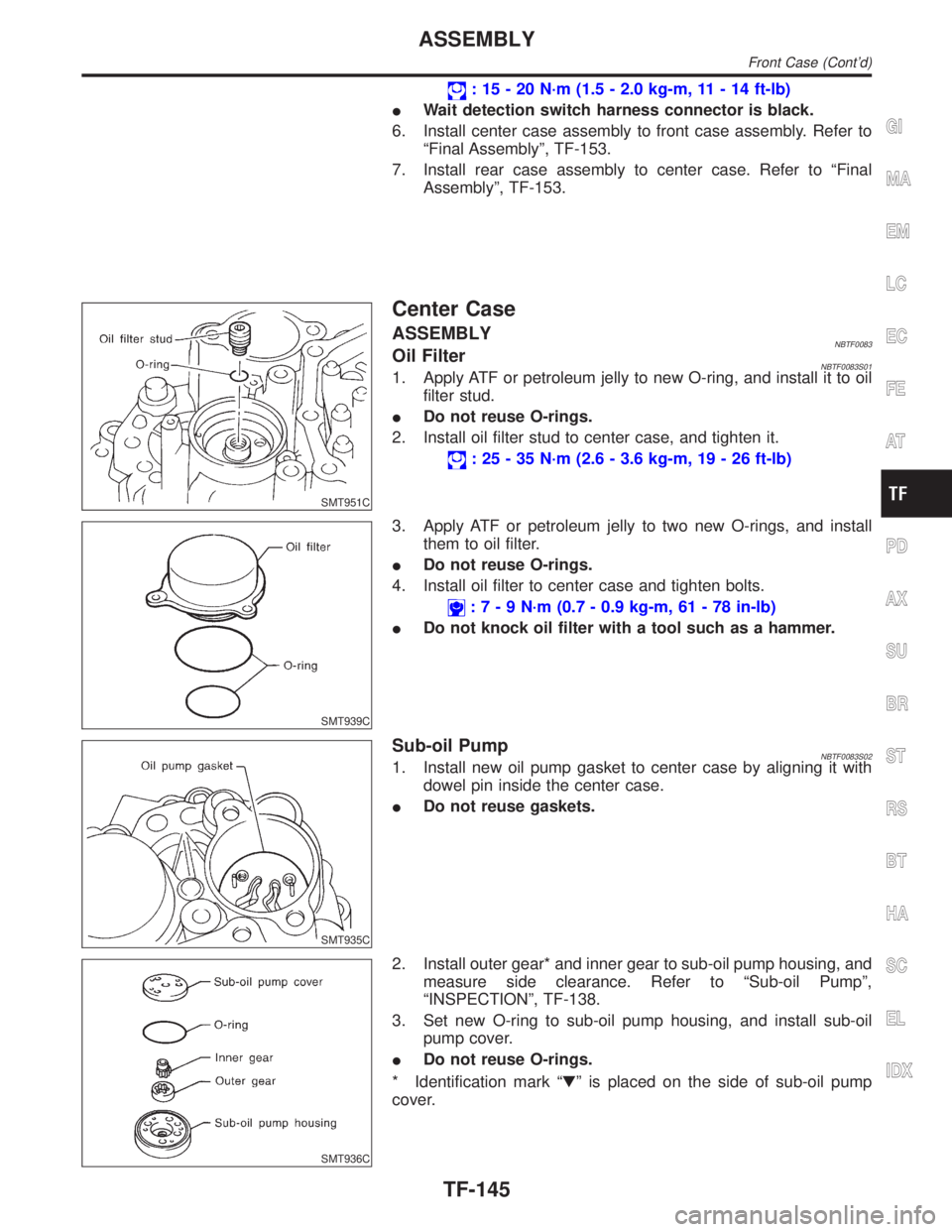
ASSEMBLYNBTF0083Oil FilterNBTF0083S011. Apply ATF or petroleum jelly to new O-ring, and install it to oil
filter stud.
IDo not reuse O-rings.
2. Install oil filter stud to center case, and tighten it.
: 25 - 35 N´m (2.6 - 3.6 kg-m, 19 - 26 ft-lb)
SMT939C
3. Apply ATF or petroleum jelly to two new O-rings, and install
them to oil filter.
IDo not reuse O-rings.
4. Install oil filter to center case and tighten bolts.
:7-9N´m(0.7 - 0.9 kg-m, 61 - 78 in-lb)
IDo not knock oil filter with a tool such as a hammer.
SMT935C
Sub-oil PumpNBTF0083S021. Install new oil pump gasket to center case by aligning it with
dowel pin inside the center case.
IDo not reuse gaskets.
SMT936C
2. Install outer gear* and inner gear to sub-oil pump housing, and
measure side clearance. Refer to ªSub-oil Pumpº,
ªINSPECTIONº, TF-138.
3. Set new O-ring to sub-oil pump housing, and install sub-oil
pump cover.
IDo not reuse O-rings.
* Identification mark ªHº is placed on the side of sub-oil pump
cover.
GI
MA
EM
LC
EC
FE
AT
PD
AX
SU
BR
ST
RS
BT
HA
SC
EL
IDX
ASSEMBLY
Front Case (Cont'd)
TF-145
Page 2382 of 2395

SMT928C
SMT926C
Control ValveNBTF0083S041. Clean upper body, control valves and springs with cleaning
agent, and apply air blow.
2. Dip control valves in ATF, and apply ATF to the valve-mount-
ing area of upper body.
3. Install each control valve, spring, and plug to upper body, and
fix it with retainer plates.
CAUTION:
ITo insert control valves into upper body, place upper body
on a level surface in order to prevent flaw or damage.
IMake sure each control valve is smoothly inserted.
4. Install reverse balls, relief balls and relief springs, accumula-
tor pistons, valve springs and two filters to upper body.
SMT925C
5. Install lower body and separator plate to upper body.
IDo not reuse separator plates.
SMT962CA
6. With lower body down, tighten two bolts in the position shown
in the figure.
7. Apply ATF or petroleum jelly to new O-ring, and install it to
2-4WD shift solenoid valve, terminal body, line pressure switch
and 4WD solenoid valve. Install them to control valve assem-
bly.
IDo not reuse O-rings.
SMT922CA
8. Apply ATF or petroleum jelly to lip seals, and install them to
center case.
IDo not reuse lip seals.
IThere are 2 kinds of lip seals (lip seal of large inner diam-
eter: 5 pieces, lip seal of small inner diameter: 2 pieces).
Confirm the position before installation.
GI
MA
EM
LC
EC
FE
AT
PD
AX
SU
BR
ST
RS
BT
HA
SC
EL
IDX
ASSEMBLY
Center Case (Cont'd)
TF-147
Page 2384 of 2395
SMT969C
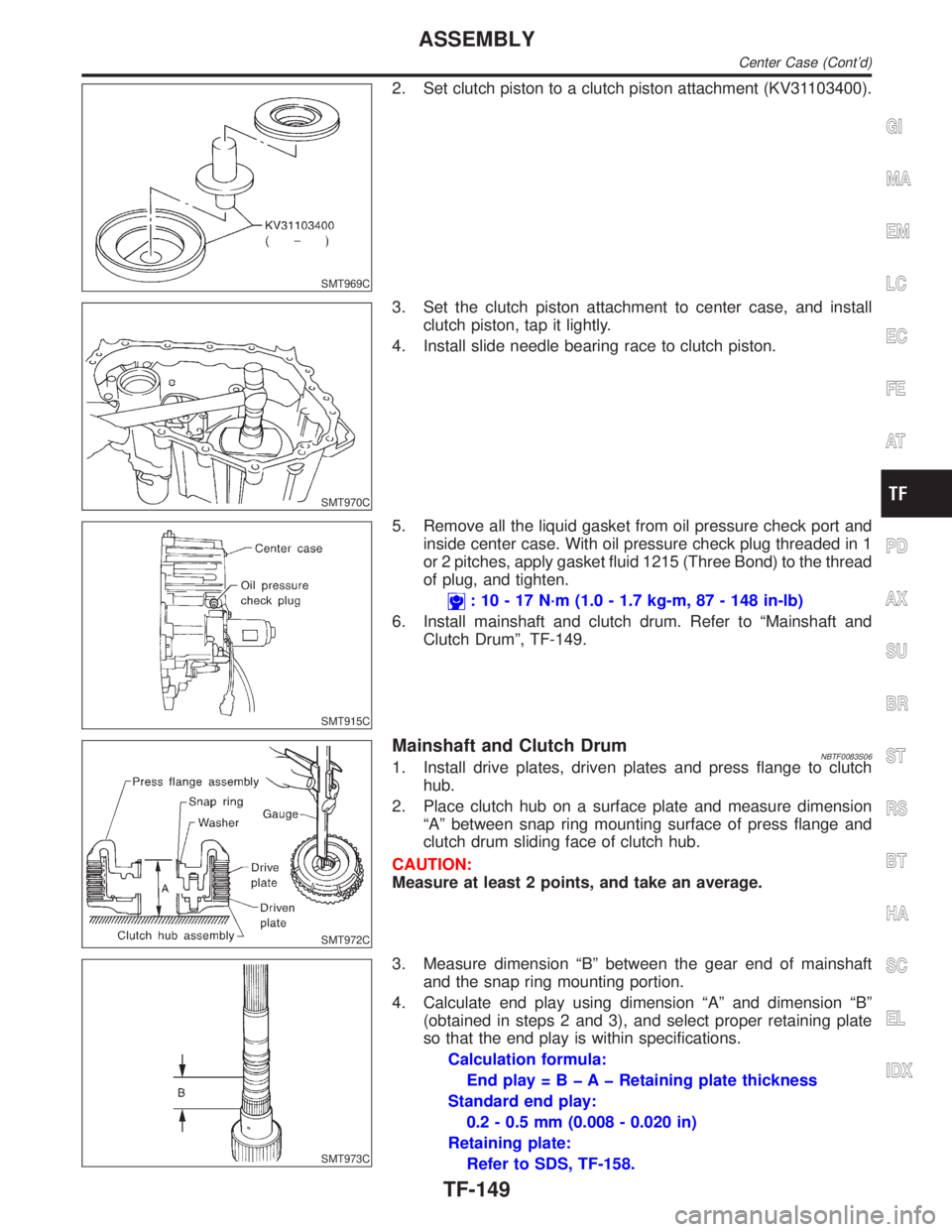
2. Set clutch piston to a clutch piston attachment (KV31103400).
SMT970C
3. Set the clutch piston attachment to center case, and install
clutch piston, tap it lightly.
4. Install slide needle bearing race to clutch piston.
SMT915C
5. Remove all the liquid gasket from oil pressure check port and
inside center case. With oil pressure check plug threaded in 1
or 2 pitches, apply gasket fluid 1215 (Three Bond) to the thread
of plug, and tighten.
: 10 - 17 N´m (1.0 - 1.7 kg-m, 87 - 148 in-lb)
6. Install mainshaft and clutch drum. Refer to ªMainshaft and
Clutch Drumº, TF-149.
SMT972C
Mainshaft and Clutch DrumNBTF0083S061. Install drive plates, driven plates and press flange to clutch
hub.
2. Place clutch hub on a surface plate and measure dimension
ªAº between snap ring mounting surface of press flange and
clutch drum sliding face of clutch hub.
CAUTION:
Measure at least 2 points, and take an average.
SMT973C
3. Measure dimension ªBº between the gear end of mainshaft
and the snap ring mounting portion.
4. Calculate end play using dimension ªAº and dimension ªBº
(obtained in steps 2 and 3), and select proper retaining plate
so that the end play is within specifications.
Calculation formula:
End play = B þ A þ Retaining plate thickness
Standard end play:
0.2 - 0.5 mm (0.008 - 0.020 in)
Retaining plate:
Refer to SDS, TF-158.
GI
MA
EM
LC
EC
FE
AT
PD
AX
SU
BR
ST
RS
BT
HA
SC
EL
IDX
ASSEMBLY
Center Case (Cont'd)
TF-149
Page 2386 of 2395
SMT907C
10. Pass mainshaft through snap ring. Set a drift (KV31103300),
a support ring (KV40104710), a support ring (ST27863000)
and a drift (ST35271000) to press flange at the position shown
in the figure, and press snap ring until it fits into snap ring
groove on mainshaft.
IDo not reuse snap ring.
SMT908C
11. Fix snap ring to mainshaft.
SMT905C
12. Install thrust needle bearing to press flange.
SMT982C
13. Apply petroleum jelly to new seal rings, and install them to
mainshaft. Measure clearance between seal ring and groove
using feeler gauge.
Standard clearance:
0.05 - 0.30 mm (0.0020 - 0.0118 in)
Limit clearance:
0.30 mm (0.0118 in)
IPass seal ring from mainshaft rear end to install it.
Seal ring dimension:
Refer to SDS, TF-159.
SMT983C
14. Install mainshaft rear bearing to center case.
GI
MA
EM
LC
EC
FE
AT
PD
AX
SU
BR
ST
RS
BT
HA
SC
EL
IDX
ASSEMBLY
Center Case (Cont'd)
TF-151