Page 2332 of 2395

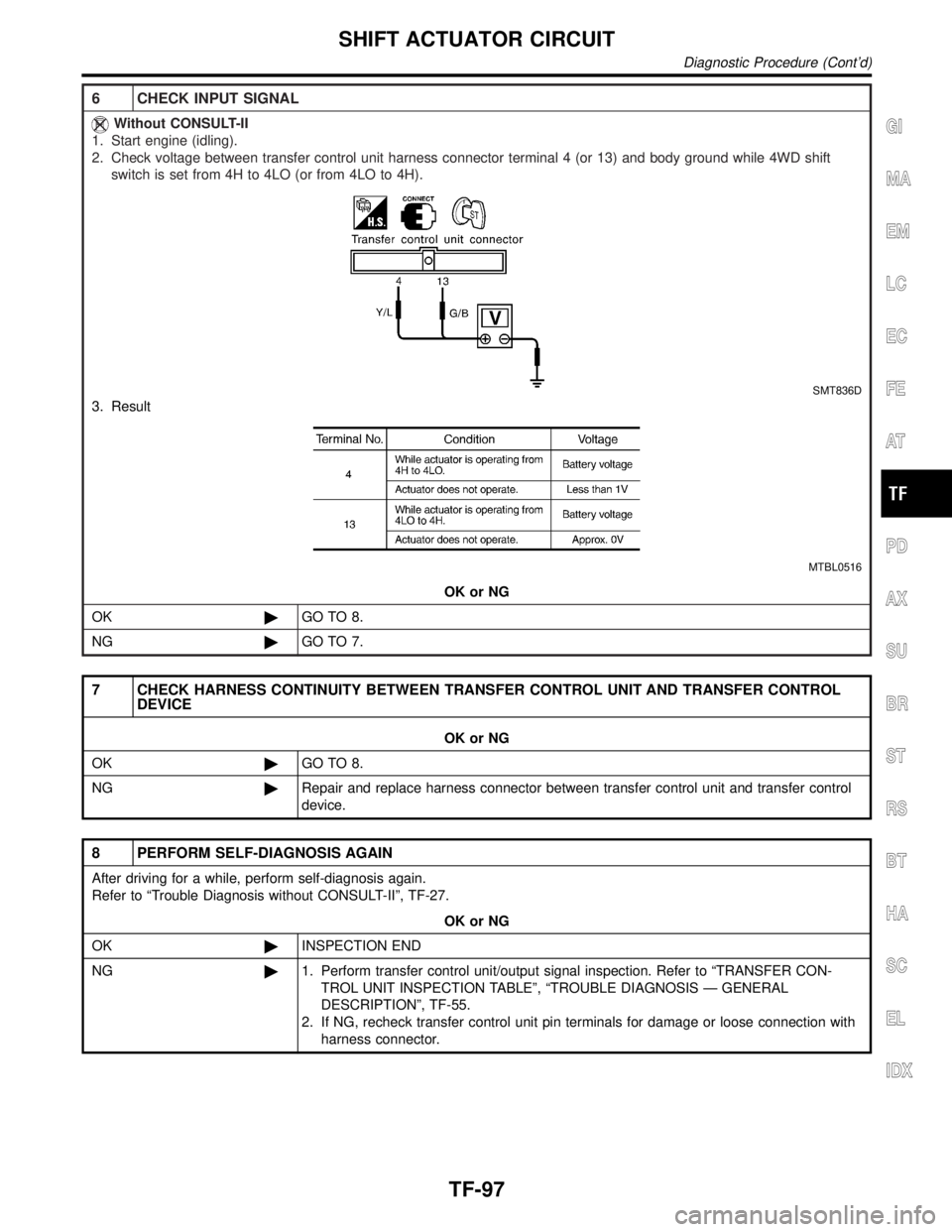
6 CHECK INPUT SIGNAL
Without CONSULT-II
1. Start engine (idling).
2. Check voltage between transfer control unit harness connector terminal 4 (or 13) and body ground while 4WD shift
switch is set from 4H to 4LO (or from 4LO to 4H).
SMT836D
3. Result
MTBL0516
OK or NG
OK©GO TO 8.
NG©GO TO 7.
7 CHECK HARNESS CONTINUITY BETWEEN TRANSFER CONTROL UNIT AND TRANSFER CONTROL
DEVICE
OK or NG
OK©GO TO 8.
NG©Repair and replace harness connector between transfer control unit and transfer control
device.
8 PERFORM SELF-DIAGNOSIS AGAIN
After driving for a while, perform self-diagnosis again.
Refer to ªTrouble Diagnosis without CONSULT-IIº, TF-27.
OK or NG
OK©INSPECTION END
NG©1. Perform transfer control unit/output signal inspection. Refer to ªTRANSFER CON-
TROL UNIT INSPECTION TABLEº, ªTROUBLE DIAGNOSIS Ð GENERAL
DESCRIPTIONº, TF-55.
2. If NG, recheck transfer control unit pin terminals for damage or loose connection with
harness connector.
GI
MA
EM
LC
EC
FE
AT
PD
AX
SU
BR
ST
RS
BT
HA
SC
EL
IDX
SHIFT ACTUATOR CIRCUIT
Diagnostic Procedure (Cont'd)
TF-97
Page 2333 of 2395
Symptom 1. 4WD Shift Indicator Lamp Does
Not Turn ON
NBTF0029SYMPTOM: Although ignition switch is turned ªONº, all the
4WD shift indicator lamps do not turn ON for 1 second.
1 CHECK TRANSFER CONTROL UNIT POWER SOURCE
SMT958D
SMT860D
1. Turn ignition switch to ªOFFº position and disconnect transfer control unit harness connector.
2. Turn ignition switch to ªONº position. (Do not start engine.)
3. Check voltage between transfer control unit harness connector terminals 16, 22 and body ground.
Voltage: Battery voltage
SMT796D
OK or NG
OK©GO TO 2.
NG©Check the following.
IContinuity between ignition switch and transfer control unit
IIgnition switch and No. 18 fuse (10A)
TROUBLE DIAGNOSES FOR SYMPTOMS
Symptom 1. 4WD Shift Indicator Lamp Does Not Turn ON
TF-98
Page 2334 of 2395
2 CHECK TRANSFER CONTROL UNIT GROUND CIRCUIT
1. Turn ignition switch to ªOFFº position.
2. Disconnect transfer control unit harness connector.
3. Measure resistance between transfer control unit harness connector terminals 6, 45 and body ground.
Resistance: 0W
SMT797D
OK or NG
OK©GO TO 3.
NG©Check continuity between transfer control unit and body ground.
3 CHECK PROCEDURES FROM THE BEGINNING AGAIN
Check again.
OK or NG
OK©INSPECTION END
NG©1. Perform transfer control unit input/output signal inspection. Refer to ªTRANSFER
CONTROL UNIT INSPECTION TABLEº, ªTROUBLE DIAGNOSIS Ð GENERAL
DESCRIPTIONº, TF-55.
2. If NG, recheck transfer control unit pin terminals for damage or loose connection with
harness connector.
GI
MA
EM
LC
EC
FE
AT
PD
AX
SU
BR
ST
RS
BT
HA
SC
EL
IDX
TROUBLE DIAGNOSES FOR SYMPTOMS
Symptom 1. 4WD Shift Indicator Lamp Does Not Turn ON (Cont'd)
TF-99
Page 2335 of 2395
Symptom 2. 4WD Warning Lamp Does Not Turn
ON
=NBTF0030SYMPTOM: Although ignition switch is turned ªONº, 4WD
warning lamp does not turn ON.
1 CHECK TRANSFER CONTROL UNIT POWER SOURCE
SMT799D
1. Turn ignition switch to ªOFFº position and disconnect transfer control unit harness connector.
2. Turn ignition switch to ªONº position.
(Do not start engine.)
3. Check voltage between transfer control unit harness connector terminals 16, 22 and body ground.
Voltage: Battery voltage
SMT800D
OK or NG
OK©GO TO 2.
NG©Check the following.
IContinuity between ignition switch and transfer control unit
IIgnition switch and No. 18 fuse (10A)
TROUBLE DIAGNOSES FOR SYMPTOMS
Symptom 2. 4WD Warning Lamp Does Not Turn ON
TF-100
Page 2336 of 2395

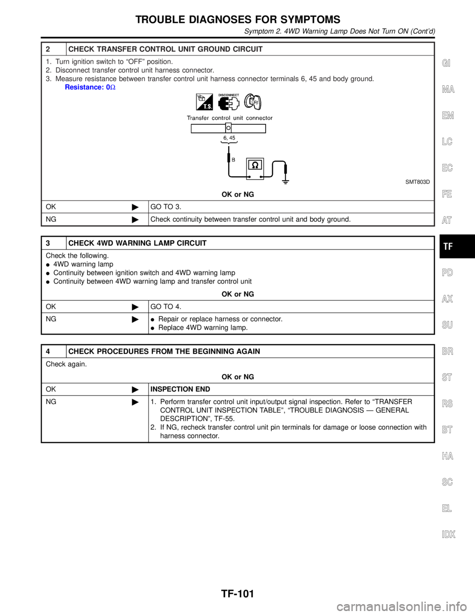
2 CHECK TRANSFER CONTROL UNIT GROUND CIRCUIT
1. Turn ignition switch to ªOFFº position.
2. Disconnect transfer control unit harness connector.
3. Measure resistance between transfer control unit harness connector terminals 6, 45 and body ground.
Resistance: 0W
SMT803D
OK or NG
OK©GO TO 3.
NG©Check continuity between transfer control unit and body ground.
3 CHECK 4WD WARNING LAMP CIRCUIT
Check the following.
I4WD warning lamp
IContinuity between ignition switch and 4WD warning lamp
IContinuity between 4WD warning lamp and transfer control unit
OK or NG
OK©GO TO 4.
NG©IRepair or replace harness or connector.
IReplace 4WD warning lamp.
4 CHECK PROCEDURES FROM THE BEGINNING AGAIN
Check again.
OK or NG
OK©INSPECTION END
NG©1. Perform transfer control unit input/output signal inspection. Refer to ªTRANSFER
CONTROL UNIT INSPECTION TABLEº, ªTROUBLE DIAGNOSIS Ð GENERAL
DESCRIPTIONº, TF-55.
2. If NG, recheck transfer control unit pin terminals for damage or loose connection with
harness connector.
GI
MA
EM
LC
EC
FE
AT
PD
AX
SU
BR
ST
RS
BT
HA
SC
EL
IDX
TROUBLE DIAGNOSES FOR SYMPTOMS
Symptom 2. 4WD Warning Lamp Does Not Turn ON (Cont'd)
TF-101
Page 2339 of 2395
Symptom 5. 4LO Indicator Lamp Does Not Turn
ON
=NBTF0033SYMPTOM: When 4WD shift switch is set from ª4Hº to
ª4LOº position, 4LO indicator lamp does not turn ON.
1 CHECK TRANSFER CONTROL UNIT POWER SUPPLY CIRCUIT
SMT958D
SMT851D
SMT979D
1. Disconnect battery negative terminal (þ), then transfer control unit connector.
2. Connect battery negative terminal (þ) and turn ignition switch ªONº (with engine stopped).
3. Check voltage across transfer control unit body-side connector terminals 47, 16 and body ground.
Voltage: Battery voltage
OK or NG
OK©GO TO 2.
NG©Check the following.
IContinuity between battery and transfer control unit
IIgnition switch (Refer to EL-9, ªPower Supply Routingº.)
INo. 24 fuse (7.5A), No. 8 fuse (10A) and No. 18 fuse (10A)
TROUBLE DIAGNOSES FOR SYMPTOMS
Symptom 5. 4LO Indicator Lamp Does Not Turn ON
TF-104
Page 2340 of 2395

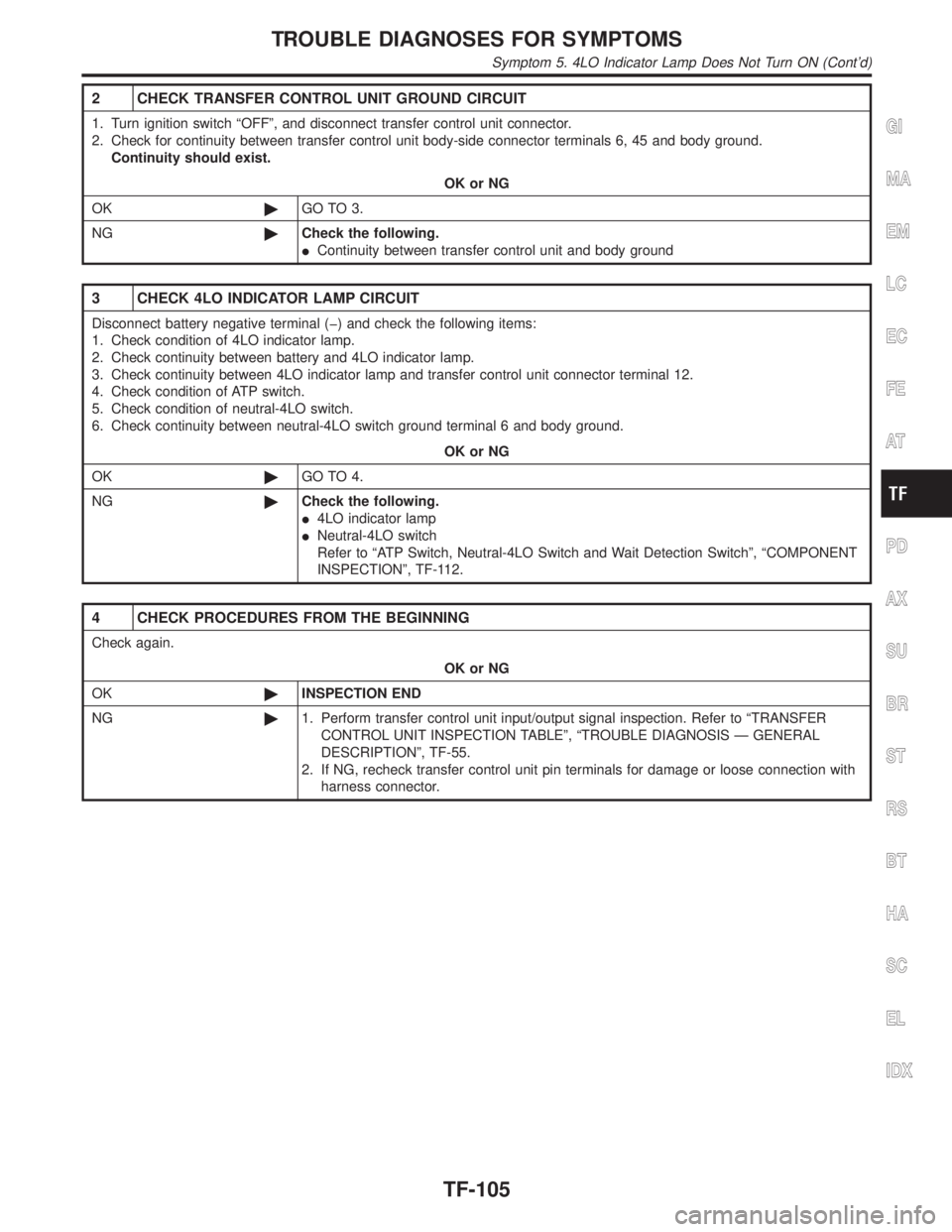
2 CHECK TRANSFER CONTROL UNIT GROUND CIRCUIT
1. Turn ignition switch ªOFFº, and disconnect transfer control unit connector.
2. Check for continuity between transfer control unit body-side connector terminals 6, 45 and body ground.
Continuity should exist.
OK or NG
OK©GO TO 3.
NG©Check the following.
IContinuity between transfer control unit and body ground
3 CHECK 4LO INDICATOR LAMP CIRCUIT
Disconnect battery negative terminal (þ) and check the following items:
1. Check condition of 4LO indicator lamp.
2. Check continuity between battery and 4LO indicator lamp.
3. Check continuity between 4LO indicator lamp and transfer control unit connector terminal 12.
4. Check condition of ATP switch.
5. Check condition of neutral-4LO switch.
6. Check continuity between neutral-4LO switch ground terminal 6 and body ground.
OK or NG
OK©GO TO 4.
NG©Check the following.
I4LO indicator lamp
INeutral-4LO switch
Refer to ªATP Switch, Neutral-4LO Switch and Wait Detection Switchº, ªCOMPONENT
INSPECTIONº, TF-112.
4 CHECK PROCEDURES FROM THE BEGINNING
Check again.
OK or NG
OK©INSPECTION END
NG©1. Perform transfer control unit input/output signal inspection. Refer to ªTRANSFER
CONTROL UNIT INSPECTION TABLEº, ªTROUBLE DIAGNOSIS Ð GENERAL
DESCRIPTIONº, TF-55.
2. If NG, recheck transfer control unit pin terminals for damage or loose connection with
harness connector.
GI
MA
EM
LC
EC
FE
AT
PD
AX
SU
BR
ST
RS
BT
HA
SC
EL
IDX
TROUBLE DIAGNOSES FOR SYMPTOMS
Symptom 5. 4LO Indicator Lamp Does Not Turn ON (Cont'd)
TF-105
Page 2343 of 2395

Symptom 8. Tight Corner Braking SymptomNBTF0036SYMPTOM: Tight corner braking symptom occurs. (Hydraulic
system failure)
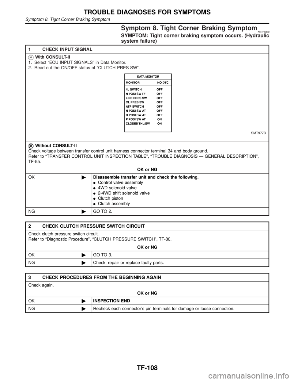
1 CHECK INPUT SIGNAL
With CONSULT-II
1. Select ªECU INPUT SIGNALSº in Data Monitor.
2. Read out the ON/OFF status of ªCLUTCH PRES SWº.
SMT977D
Without CONSULT-II
Check voltage between transfer control unit harness connector terminal 34 and body ground.
Refer to ªTRANSFER CONTROL UNIT INSPECTION TABLEº, ªTROUBLE DIAGNOSIS Ð GENERAL DESCRIPTIONº,
TF-55.
OK or NG
OK©Disassemble transfer unit and check the following.
IControl valve assembly
I4WD solenoid valve
I2-4WD shift solenoid valve
IClutch piston
IClutch assembly
NG©GO TO 2.
2 CHECK CLUTCH PRESSURE SWITCH CIRCUIT
Check clutch pressure switch circuit.
Refer to ªDiagnostic Procedureº, ªCLUTCH PRESSURE SWITCHº, TF-80.
OK or NG
OK©GO TO 3.
NG©Check, repair or replace faulty parts.
3 CHECK PROCEDURES FROM THE BEGINNING AGAIN
Check again.
OK or NG
OK©INSPECTION END
NG©Recheck each connector's pin terminals for damage or loose connection.
TROUBLE DIAGNOSES FOR SYMPTOMS
Symptom 8. Tight Corner Braking Symptom
TF-108