2001 INFINITI QX4 Transfer Control Unit
[x] Cancel search: Transfer Control UnitPage 2267 of 2395

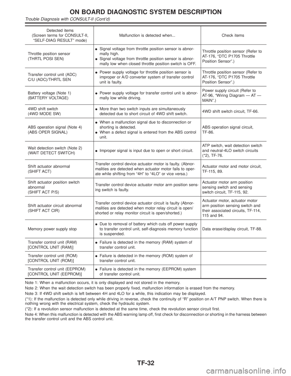
Detected items
(Screen terms for CONSULT-II,
ªSELF-DIAG RESULTº mode)Malfunction is detected when... Check items
Throttle position sensor
(THRTL POSI SEN)ISignal voltage from throttle position sensor is abnor-
mally high.
ISignal voltage from throttle position sensor is abnor-
mally low when closed throttle position switch is OFF.Throttle position sensor (Refer to
AT-176, ªDTC P1705 Throttle
Position Sensorº.)
Transfer control unit (ADC)
C/U (ADC)/THRTL SENIPower supply voltage for throttle position sensor is
improper or A/D converter system of transfer control
unit is faulty.Throttle position sensor (Refer to
AT-176, ªDTC P1705 Throttle
Position Sensorº.)
Battery voltage (Note 1)
(BATTERY VOLTAGE)IPower supply voltage for transfer control unit is abnor-
mally low while driving.Power supply circuit (Refer to
AT-96, ªWiring Diagram Ð AT Ð
MAINº.)
4WD shift switch
(4WD MODE SW)IMore than two switch inputs are simultaneously
detected due to short circuit of 4WD shift switch.4WD shift switch circuit, TF-66.
ABS operation signal (Note 4)
(ABS OPER SIGNAL)IWhen a malfunction signal due to disconnection or
shorting is detected.
IWhen a defect signal is entered from the ABS control
unit.ABS operation signal circuit,
TF-86.
Wait detection switch (Note 2)
(WAIT DETECT SWITCH)IImproper signal is input due to open or short circuit.ATP switch, wait detection switch
and neutral-4LO switch circuits
(*2), TF-76.
Shift actuator abnormal
(SHIFT ACT)Transfer control device actuator motor is faulty. (Abnor-
malities are detected when actuator motor fails to oper-
ate while shifting from ª4Hº to ª4LOº or vice versa.)Actuator motor and motor circuit,
TF-115, 89.
Shift actuator position switch
abnormal
(SHIFT ACT P/S)Transfer control device actuator motor arm position sens-
ing switch is faulty.Actuator motor arm position
sensing switch and sensing
switch circuit, TF-115, 92.
Shift actuator circuit abnormal
(SHIFT ACT CIR)Transfer control device actuator circuit is faulty (Abnor-
malities are detected when motor relay circuit is open/
shorted or relay monitor circuit is open/shorted.)Actuator motor, actuator motor
arm position sensing switch and
their associated circuits, TF-114,
115 and 94.
Memory power supply stopIDue to removal of battery which cuts off power supply
to transfer control unit, self-diagnosis memory function
is suspended.Data erase/display circuit, TF-88.
Transfer control unit (RAM)
[CONTROL UNIT (RAM)]IFailure is detected in the memory (RAM) system of
transfer control unit.
Transfer control unit (ROM)
[CONTROL UNIT (ROM)]IFailure is detected in the memory (ROM) system of
transfer control unit.
Transfer control unit (EEPROM)
[CONTROL UNIT (EEPROM)]IFailure is detected in the memory (EEPROM) system
of transfer control unit.
Note 1: When a malfunction occurs, it is only displayed and not stored in the memory.
Note 2: When the wait detection switch has been properly fixed, malfunction information is erased from the memory.
Note 3: If 4WD shift switch is left between 4H and 4LO for a while, this indication may be displayed.
(*1): If the malfunction is detected only while driving in reverse, check the continuity of ªRº position on A/T PNP switch. When there is
nothing wrong with the electrical system, check the hydraulic system.
(*2): If a revolution sensor malfunction is detected at the same time, check the revolution sensor circuit first.
Note 4: When this malfunction is detected with the ABS warning lamp off, first check for disconnection or shorting in the harness between
the transfer control unit and the ABS control unit.
ON BOARD DIAGNOSTIC SYSTEM DESCRIPTION
Trouble Diagnosis with CONSULT-II (Cont'd)
TF-32
Page 2269 of 2395
![INFINITI QX4 2001 Factory Service Manual SMT963D
12. Monitored data are displayed.
DATA MONITOR ITEMSNBTF0012S04q: StandardH: Option
Item [Unit]Monitor item
Remarks
ECU input
signalsMain sig-
nalsItem menu
selection
Revolution sensor-front [ INFINITI QX4 2001 Factory Service Manual SMT963D
12. Monitored data are displayed.
DATA MONITOR ITEMSNBTF0012S04q: StandardH: Option
Item [Unit]Monitor item
Remarks
ECU input
signalsMain sig-
nalsItem menu
selection
Revolution sensor-front [](/manual-img/42/57027/w960_57027-2268.png)
SMT963D
12. Monitored data are displayed.
DATA MONITOR ITEMSNBTF0012S04q: StandardH: Option
Item [Unit]Monitor item
Remarks
ECU input
signalsMain sig-
nalsItem menu
selection
Revolution sensor-front [km/h (MPH)]qHRevolution sensor installed on T/F
Revolution sensor-rear [km/h (MPH)]qHVehicle speed sensor´A/T
Engine speed [rpm]qH
Throttle position sensor [V]qH
Transfer fluid temperature sensor [V]qH
Battery voltage [V]qH
2WD switch [ON-OFF]qH2WD switch of 4WD shift switch
AUTO switch [ON-OFF]qHAUTO switch of 4WD shift switch
Lock switch [ON-OFF]qH4H switch of 4WD shift switch
4L switch [ON-OFF]qH4LO switch of 4WD shift switch
N position switch TF [ON-OFF]qHN position switch of transfer
Line pressure switch [ON-OFF]qHLine pressure switch
Clutch pressure switch [ON-OFF]qHClutch pressure switch
ATP switch [ON-OFF]qH
N position switch [ON-OFF]qHªNº position on A/T PNP switch
R position switch [ON-OFF]qHªRº position on A/T PNP switch
P position switch [ON-OFF]qHªPº position on A/T PNP switch
Closed throttle position switch
[ON/OFF]qHIdle contact of throttle position switch
ABS operation switch [ON-OFF]qHABS operation switch
Wait detection switch [ON-OFF]qH
Throttle openingqHThrottle opening recognized by transfer control
unit
4WD-modeqH4WD-mode recognized by transfer control unit
(2W, AUTO, 4H & 4LO)
Vehicle speed comp [km/h (MPH)]qHVehicle speed recognized by transfer control
unit
*Control torque [N´m (kg-m, ft-lb)]qHCalculated torque recognized by transfer control
unit
ON BOARD DIAGNOSTIC SYSTEM DESCRIPTION
Trouble Diagnosis with CONSULT-II (Cont'd)
TF-34
Page 2270 of 2395
![INFINITI QX4 2001 Factory Service Manual Item [Unit]Monitor item
Remarks
ECU input
signalsMain sig-
nalsItem menu
selection
Duty solenoid valve [%]
(Transfer 4WD solenoid valve)qH
2-4WD shift solenoid valve [ON-OFF]qH
Control signal outputs INFINITI QX4 2001 Factory Service Manual Item [Unit]Monitor item
Remarks
ECU input
signalsMain sig-
nalsItem menu
selection
Duty solenoid valve [%]
(Transfer 4WD solenoid valve)qH
2-4WD shift solenoid valve [ON-OFF]qH
Control signal outputs](/manual-img/42/57027/w960_57027-2269.png)
Item [Unit]Monitor item
Remarks
ECU input
signalsMain sig-
nalsItem menu
selection
Duty solenoid valve [%]
(Transfer 4WD solenoid valve)qH
2-4WD shift solenoid valve [ON-OFF]qH
Control signal outputs of transfer control unit Transfer motor relay [ON-OFF]qH
Shift activating 1 [ON-OFF]qH
Shift activating 2 [ON-OFF]qH
2-4WD shift solenoid valve monitor
[ON-OFF]H
Check signal (re-input signal) of transfer control
unit control signal output is displayed. If circuit
is shorted or open, ON/OFF state does not
change. Transfer motor relay monitor [ON-OFF]H
Shift activating monitor 1 [ON-OFF]H
Shift activating monitor 2 [ON-OFF]H
4WD fail lamp [ON-OFF]qHTransfer control unit control signal output for
4WD warning lamp (left)
Shift position switch 1 [ON-OFF]qH
Shift position switch 2 [ON-OFF]qH
2WD indicator lamp [ON-OFF]HTransfer control unit control signal output for
4WD shift indicator lamp (rear)
AUTO indicator lamp [ON-OFF]HTransfer control unit control signal output for
4WD shift indicator lamp (front & rear)
LOCK indicator lamp [ON-OFF]HTransfer control unit control signal output for
4WD shift indicator lamp (center)
4LO indicator lamp [ON-OFF]HTransfer control unit control signal output for
4WD shift indicator lamp (right)
Offset at startingHAppears on monitor but does not function.
Clutch limit [N´m (kg-m, ft-lb)]HClutch force release limit value set in WORK
SUPPORT
Voltage [V]HValue measured by voltage probe is displayed.
Frequency [Hz]HValue measured by pulse probe is displayed. If
measurement is impossible, ª#º sign is dis-
played. ª#º sign is also displayed at the final
data value until the measurement result is
obtained.
DUTY-HIH
Duty cycle value for measurement probe is dis-
played.
DUTY-LOWH
PLS WIDTH-HIH
Measured pulse width of measurement probe is
displayed.
PLS WIDTH-LOWH
*: This item is indicated as ªCOMP CL TORQº.GI
MA
EM
LC
EC
FE
AT
PD
AX
SU
BR
ST
RS
BT
HA
SC
EL
IDX
ON BOARD DIAGNOSTIC SYSTEM DESCRIPTION
Trouble Diagnosis with CONSULT-II (Cont'd)
TF-35
Page 2276 of 2395

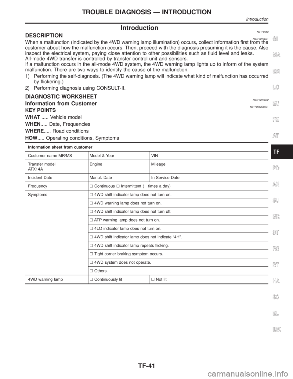
IntroductionNBTF0013DESCRIPTIONNBTF0013S01When a malfunction (indicated by the 4WD warning lamp illumination) occurs, collect information first from the
customer about how the malfunction occurs. Then, proceed with the diagnosis presuming it is the cause. Also
inspect the electrical system, paying close attention to other possibilities such as fluid level and leaks.
All-mode 4WD transfer is controlled by transfer control unit and sensors.
If a malfunction occurs in the all-mode 4WD system, the 4WD warning lamp lights up to inform of the system
malfunction. There are two ways to identify the cause of the malfunction.
1) Performing the self-diagnosis. (The 4WD warning lamp will indicate what kind of malfunction has occurred
by flickering.)
2) Performing diagnosis using CONSULT-II.
DIAGNOSTIC WORKSHEETNBTF0013S02Information from CustomerNBTF0013S0201KEY POINTS
WHAT..... Vehicle model
WHEN..... Date, Frequencies
WHERE..... Road conditions
HOW..... Operating conditions, Symptoms
Information sheet from customer
Customer name MR/MS Model & Year VIN
Transfer model
ATX14AEngine Mileage
Incident Date Manuf. Date In Service Date
FrequencylContinuouslIntermittent ( times a day)
Symptomsl4WD shift indicator lamp does not turn on.
l4WD warning lamp does not turn on.
l4WD shift indicator lamp does not turn off.
lATP warning lamp does not turn on.
l4LO indicator lamp does not turn on.
l4WD shift indicator lamp does not indicate ª4Hº.
l4WD shift indicator lamp repeats flicking.
lTight corner braking symptom occurs.
l4WD system does not operate.
lOthers.
4WD warning lamplContinuously litlNot lit
GI
MA
EM
LC
EC
FE
AT
PD
AX
SU
BR
ST
RS
BT
HA
SC
EL
IDX
TROUBLE DIAGNOSIS Ð INTRODUCTION
Introduction
TF-41
Page 2289 of 2395

SMT862D
Transfer Control Unit Terminals and Reference
Value
NBTF0018REMOVAL AND INSTALLATION OF TRANSFER
CONTROL UNIT
NBTF0018S03RemovalNBTF0018S03011. Turn ignition switch OFF and disconnect negative battery ter-
minal.
2. Remove console box.
3. Remove cluster lid C.
4. Remove audio assembly and A/C control unit.
5. Remove instrument lower panel on driver side.
6. Remove glove box.
7. Remove instrument lower panel on passenger side.
8. Remove instrument lower center panel.
9. Remove transfer control unit.
IFor steps 2 through 8 above, refer to BT-21, ªInstrument Panel
Assemblyº.
InstallationNBTF0018S0302IInstallation is in the reverse order of removal.
When installing transfer control unit, tighten transfer control unit
lock nut.
Tightening torque:
: 4.3 - 5.8 N´m (0.44 - 0.59 kg-m, 38 - 51 in-lb)
SMT771D
INSPECTION OF TRANSFER CONTROL UNITNBTF0018S01IMeasure voltage between each terminal and terminal 6 or 45
by following ªTRANSFER CONTROL UNIT INSPECTION
TABLEº, TF-55.
IPin connector terminal layout
TROUBLE DIAGNOSIS Ð GENERAL DESCRIPTION
Transfer Control Unit Terminals and Reference Value
TF-54
Page 2290 of 2395

SMT772D
TRANSFER CONTROL UNIT INSPECTION TABLENBTF0018S02(Data are reference values.)
Terminal
No.Item Condition Judgement standard
12-4WD shift solenoid
valve
&
4WD shift switch is set to ª2WDº
position.Less than 1V
4WD shift switch is set to any posi-
tion other than ª2WDº.Battery voltage
24WD shift indicator lamp
(2WD)
Lamp lights while system is operating
properly.Less than 1V
&
2WD indicator lamp does not come
on.Battery voltage
3 Ground Ð Ð
4Transfer shift relay
(High)While actuator is operating
(4H,4LO)Battery voltage
Actuator does not operate. Less than 1V
5 4WD warning lampLamp comes ON. (when engine is
stopped.)
(Fail-safe condition appears on
display, engine is stopped, actuator
position detection switch is
inoperative, oil temperature is too
high and/or tires of different size are
installed.)Less than 1V
Except above Battery voltage
6 Ground Ð Ð Ð
7 PNP switch (R position)
&
A/T selector lever is set to ªreverseº
position.Battery voltage
A/T selector lever is set to any posi-
tion other than ªreverseº.Less than 1V
8ÐÐÐÐ
GI
MA
EM
LC
EC
FE
AT
PD
AX
SU
BR
ST
RS
BT
HA
SC
EL
IDX
TROUBLE DIAGNOSIS Ð GENERAL DESCRIPTION
Transfer Control Unit Terminals and Reference Value (Cont'd)
TF-55
Page 2291 of 2395

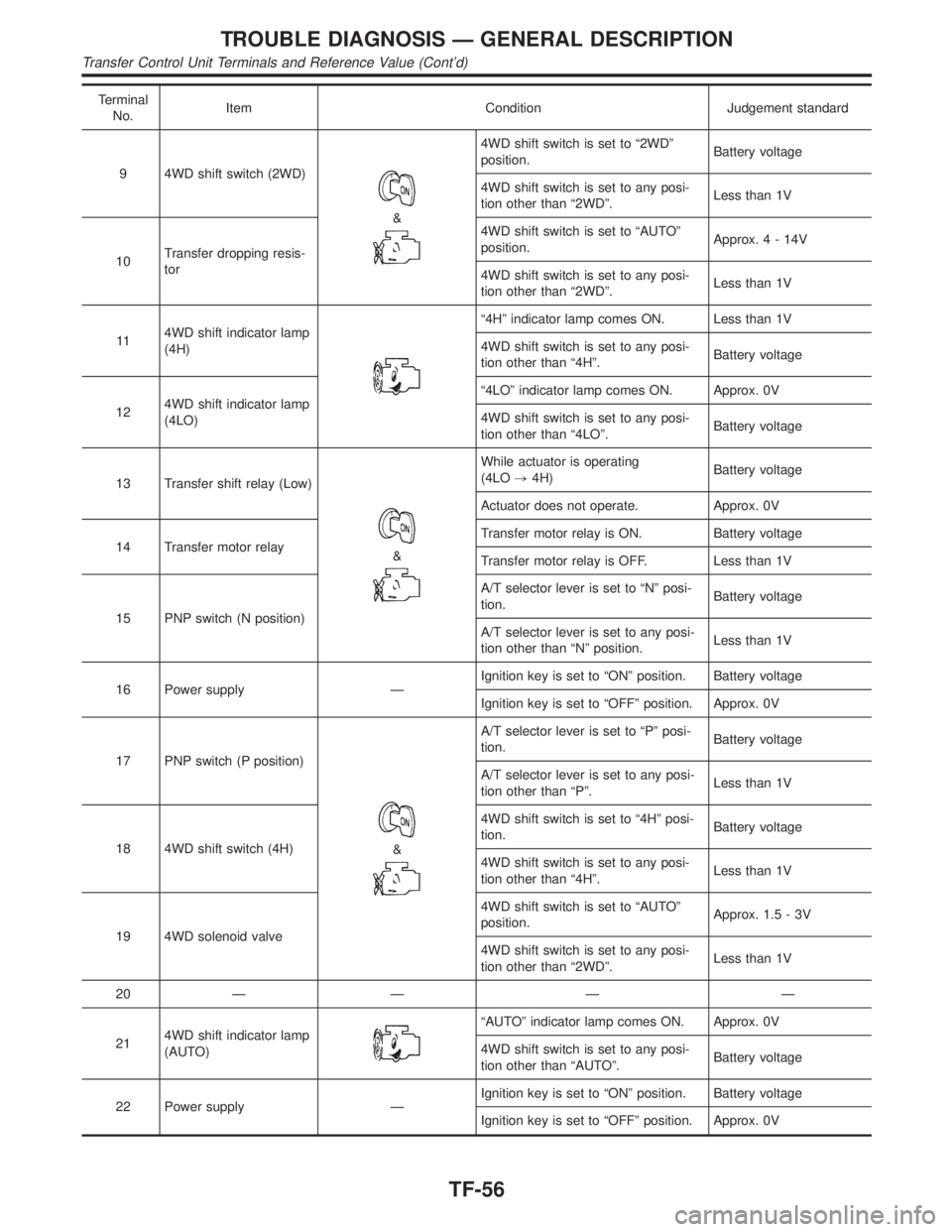
Terminal
No.Item Condition Judgement standard
9 4WD shift switch (2WD)
&
4WD shift switch is set to ª2WDº
position.Battery voltage
4WD shift switch is set to any posi-
tion other than ª2WDº.Less than 1V
10Transfer dropping resis-
tor4WD shift switch is set to ªAUTOº
position.Approx.4-14V
4WD shift switch is set to any posi-
tion other than ª2WDº.Less than 1V
114WD shift indicator lamp
(4H)
ª4Hº indicator lamp comes ON. Less than 1V
4WD shift switch is set to any posi-
tion other than ª4Hº.Battery voltage
124WD shift indicator lamp
(4LO)ª4LOº indicator lamp comes ON. Approx. 0V
4WD shift switch is set to any posi-
tion other than ª4LOº.Battery voltage
13 Transfer shift relay (Low)
&
While actuator is operating
(4LO,4H)Battery voltage
Actuator does not operate. Approx. 0V
14 Transfer motor relayTransfer motor relay is ON. Battery voltage
Transfer motor relay is OFF. Less than 1V
15 PNP switch (N position)A/T selector lever is set to ªNº posi-
tion.Battery voltage
A/T selector lever is set to any posi-
tion other than ªNº position.Less than 1V
16 Power supply ÐIgnition key is set to ªONº position. Battery voltage
Ignition key is set to ªOFFº position. Approx. 0V
17 PNP switch (P position)
&
A/T selector lever is set to ªPº posi-
tion.Battery voltage
A/T selector lever is set to any posi-
tion other than ªPº.Less than 1V
18 4WD shift switch (4H)4WD shift switch is set to ª4Hº posi-
tion.Battery voltage
4WD shift switch is set to any posi-
tion other than ª4Hº.Less than 1V
19 4WD solenoid valve4WD shift switch is set to ªAUTOº
position.Approx. 1.5 - 3V
4WD shift switch is set to any posi-
tion other than ª2WDº.Less than 1V
20ÐÐÐÐ
214WD shift indicator lamp
(AUTO)
ªAUTOº indicator lamp comes ON. Approx. 0V
4WD shift switch is set to any posi-
tion other than ªAUTOº.Battery voltage
22 Power supply ÐIgnition key is set to ªONº position. Battery voltage
Ignition key is set to ªOFFº position. Approx. 0V
TROUBLE DIAGNOSIS Ð GENERAL DESCRIPTION
Transfer Control Unit Terminals and Reference Value (Cont'd)
TF-56
Page 2292 of 2395

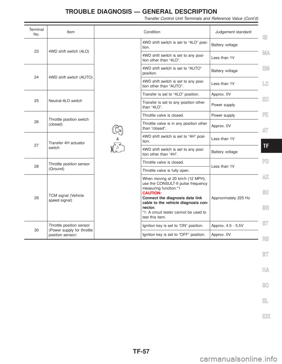
Terminal
No.Item Condition Judgement standard
23 4WD shift switch (4LO)
&
4WD shift switch is set to ª4LOº posi-
tion.Battery voltage
4WD shift switch is set to any posi-
tion other than ª4LOº.Less than 1V
24 4WD shift switch (AUTO)4WD shift switch is set to ªAUTOº
position.Battery voltage
4WD shift switch is set to any posi-
tion other than ªAUTOº.Less than 1V
25 Neutral-4LO switchTransfer is set to ª4LOº position. Approx. 0V
Transfer is set to any position other
than ª4LOº.Power supply
26Throttle position switch
(closed)Throttle valve is closed. Power supply
Throttle valve is in any position other
than ªclosedº.Approx. 0V
27Transfer 4H actuator
switch4WD shift switch is set to ª4Hº posi-
tion.Less than 1V
4WD shift switch is set to any posi-
tion other than ª4Hº.Battery voltage
28Throttle position sensor
(Ground)Throttle valve is closed.
Less than 1V
Throttle valve is fully open.
29TCM signal (Vehicle
speed signal)When moving at 20 km/h (12 MPH),
use the CONSULT-II pulse frequency
measuring function.*1
CAUTION:
Connect the diagnosis data link
cable to the vehicle diagnosis con-
nector.
*1: A circuit tester cannot be used to
test this item.Approximately 225 Hz
30Throttle position sensor
(Power supply for throttle
position sensor)Ignition key is set to ªONº position. Approx. 4.5 - 5.5V
Ignition key is set to ªOFFº position. Approx. 0VGI
MA
EM
LC
EC
FE
AT
PD
AX
SU
BR
ST
RS
BT
HA
SC
EL
IDX
TROUBLE DIAGNOSIS Ð GENERAL DESCRIPTION
Transfer Control Unit Terminals and Reference Value (Cont'd)
TF-57