2001 INFINITI QX4 Transfer Control Unit
[x] Cancel search: Transfer Control UnitPage 1966 of 2395
Propeller shaft greasing .................................MA-23
Propeller shaft inspection ..............................MA-23
Propeller shaft on vehicle service ....................PD-6
Propeller shaft vibration ...................................PD-6
PST/SW - Wiring diagram ............................EC-635
R
Rack retainer adjustment ..................................ST-8
Radiator ....................................................LC-19, 21
Radio - See Audio.........................................EL-160
Rear air spoiler ...............................................BT-35
Rear axle ........................................................AX-17
Rear bumper ...................................................BT-15
Rear case (Transfer) .....................................TF-123
Rear combination lamp removal and
installation ...................................................BT-35
Rear cover packing replacement diff. ............PD-16
Rear door ........................................................BT-20
Rear drum brake ............................................BR-26
Rear heated oxygen sensor
(HO2S) .............................EC-247, 257, 267, 277
Rear heated oxygen sensor (HO2S)
heater ........................................................EC-286
Rear seat ........................................................BT-44
Rear seat belt ...................................................RS-5
Rear side window ...........................................BT-55
Rear suspension ............................................SU-15
Rear washer..................................................EL-141
Rear window defogger ..................................EL-151
Rear wiper.....................................................EL-141
REF - Wiring diagram ..................................EC-510
Refregerant pressure sensor ........................HA-111
Refrigerant connection precaution ...................HA-4
Refrigerant discharging evacuating
charging ....................................................HA-144
Refrigerant general precaution.........................HA-3
Refrigerant lines ...........................................HA-154
Refrigerant pressure sensor.........................EC-639
Refrigeration cycle..........................................HA-14
REMOTE - Wiring diagram ...........................EL-168
Removal and installation (A/T) ......................AT-277
Removal and installation (Transfer) ..............TF-119
Reverse clutch...............................................AT-314
Revolution sensor (A/T).................................AT-115
Ring gear diff. inspection .........................PD-23, 47
RO2H-L - Wiring diagram.............................EC-290
RO2H-R - Wiring diagram ............................EC-289
Road wheel size ..............................................GI-44
Roof trim .........................................................BT-32
Room lamp - See Interior lamp ......................EL-88
RRO2LH - Wiring diagram...EC-251, 261, 271, 281
RRO2RH - Wiring diagram ..EC-250, 260, 270, 280
S
SAE J1930 terminology list .............................GI-51
Screw jack .......................................................GI-45Seal - See Exterior .........................................BT-35
SEAT - Wiring diagram .................................EL-181
Seat belt inspection .............................MA-28, RS-7
Seat belt pre-tensioner .....................................RS-3
Seat belt pre-tensioner disposal ....................RS-22
Seat belt, front ..................................................RS-4
Seat belt, rear...................................................RS-5
Seat, front .......................................................BT-41
Seat, rear ........................................................BT-44
Self-diagnosis (Transfer) .................................TF-27
SHIFT - Wiring diagram ................................AT-266
Shift lock system ...........................................AT-265
Shift schedule ................................................AT-356
Shift solenoid valve A (A/T) ..AT-125, 137, 147, 171
Shift solenoid valve B (A/T) ..AT-125, 131, 147, 175
Shock absorber (rear) ....................................SU-18
Side air bag ....................................................RS-21
Side bearing preload (front final drive
4WD) ...........................................................PD-24
Side trim ..........................................................BT-28
Side window - See Rear side window ............BT-55
Smart entrance control unit ..........................EL-319
SMJ (super multiple junction) .......................Foldout
Spare tire size .................................................GI-44
Spark plug replacement .................................MA-19
Speedometer...................................................EL-94
Spiral cable.....................................................RS-17
Spot lamp ........................................................EL-88
Spring (Wheelarch) height ...............................SU-5
SROOF - Wiring diagram .............................EL-174
SRS - See Supplemental Restraint
System ........................................................RS-10
SRS - Wiring diagram ....................................RS-35
S/SIG - Wiring diagram ................................EC-622
Stabilizer bar (front)........................................SU-10
Stabilizer bar (rear) ........................................SU-20
Stall test (A/T) .................................................AT-59
Standardized relay ............................................EL-7
START - Wiring diagram.................................SC-11
Start signal ...................................................EC-621
Starter .............................................................SC-18
Starting system...............................................SC-10
Steering gear, linkage and transfer
gear inspection ...........................................MA-26
Steering linkage ..............................................ST-17
Steering switch................................................EL-30
Steering transfer gear .....................................ST-15
Steering wheel and column.............................ST-11
Steering wheel play ..........................................ST-7
Steering wheel turning force .............................ST-9
Stop lamp ........................................................EL-67
STOP/L - Wiring diagram................................EL-67
Strut (front) .......................................................SU-8
Sub-oil pump (Transfer) ................................TF-131
Sun gear (Transfer).......................................TF-134
Sun roof, electric ...........................................EL-173
Sunload sensor ............................................HA-135
Sunroof............................................................BT-45
Supplemental Restraint System .....................RS-10
Supplemental restraint system - Wiring
diagram .......................................................RS-35
GI
MA
EM
LC
EC
FE
AT
TF
PD
AX
SU
BR
ST
RS
BT
HA
SC
EL
ALPHABETICAL INDEX
IDX-7
Page 1967 of 2395
S/VCSW - Wiring diagram ...........................EC-493
Swirl control valve control solenoid
valve .........................................................EC-458
Swirl control valve control vacuum
check switch .............................................EC-493
SWL/V - Wiring diagram ..............................EC-458
Symbols and abbreviations .............................GI-10
Symptom matrix chart...................................EC-118
System readiness test (SRT) code ................EC-61
T
2-4WD shift solenoid valve............................TF-111
Tachometer .....................................................EL-94
Tail lamp ..........................................................EL-61
TAIL/L - Wiring diagram ..................................EL-63
TCM circuit diagram ........................................AT-13
TCM inspection table ......................................AT-92
TFTS - Wiring diagram .................................EC-311
THEFT - Wiring diagram ...............................EL-300
Theft warning system....................................EL-294
Thermometer .................................................EL-110
Thermostat ......................................................LC-16
Three way catalyst function (Left bank) .......EC-347
Three way catalyst function (Right
bank) .........................................................EC-347
Three way catalyst precautions.........................GI-6
Throttle bodies ...............................................EM-12
Throttle position sensor (TPS) .....................EC-174
Throttle position sensor adjustment .............EC-101
Throttle position switch ...........EC-431, AT-184, 264
Tie-rod .............................................................ST-21
Tie-rod ball joints.............................................ST-21
Tightening torque of standard bolts.................GI-50
Timing chain ...................................................EM-20
Tire rotation ....................................................MA-24
Tire size ...........................................................GI-44
TLID - Wiring diagram ..................................EL-179
Tooth contact (front final drive 4WD) .............PD-29
Tooth contact diff. ...........................................PD-56
Torque converter installation .........................AT-278
Torque convertor clutch solenoid
valve ..................................................AT-152, 161
Tow truck towing ..............................................GI-47
Towing point.....................................................GI-49
TP/SW - Wiring diagram ..............................EC-434
TPS - Wiring diagram...................................EC-180
Transfer control unit inspection table..............TF-55
Transfer dropping resistor .............................TF-112
Transfer fluid replacement (Part time
4WD model) ...............................................MA-22
Transfer fluid temperature sensor .................TF-111
Transfer motor ...............................................TF-117
Transfer motor relay ......................................TF-113
Transfer serial number ....................................GI-43
TRANSMT - Wiring diagram .........................EL-325
Tread-FR&RR (Dimensions)............................GI-43
Trim .................................................................BT-28
Trouble diagnoses ...........................................GI-34
Trunk lid opener, electric...............................EL-178Turbine revolution sensor..............................AT-202
TURN - Wiring diagram ..................................EL-77
Turn signal lamp .............................................EL-75
Two trip detection logic ..................................EC-59
Two-pole lift .....................................................GI-47
U
Under body .....................................................BT-60
V
Vacuum cut valve ...........................................EC-32
Vacuum cut valve bypass valve.....EC-32, 585, 591
Vacuum hose (brake system).........................BR-21
Vacuum hose drawing (Engine control) .........EC-26
Valve clearance ..............................................EM-52
Valve guide.....................................................EM-43
Valve seat.......................................................EM-45
Valve spring....................................................EM-46
Vehicle identification number...........................GI-42
Vehicle recovery (freeing a stuck
vehicle) .........................................................GI-49
Vehicle speed sensor (VSS) ........................EC-417
VENT/V - Wiring diagram ............EC-376, 555, 576
Ventilation air filter ........................................HA-159
VIAS .............................................................EC-610
VIAS - Wiring diagram .................................EC-610
Viscosity number (SAE) .................................MA-12
VSS - Wiring diagram ..................................EC-420
W
Wait detection switch ....................................TF-112
WARN - Wiring diagram................................EL-115
Warning chime ..............................................EL-125
Warning lamps ..............................................EL-114
Washer, front .................................................EL-136
Washer, rear..................................................EL-141
Water pump ....................................................LC-12
Water temperature gauge ...............................EL-94
Weatherstrip - See Exterior ............................BT-35
Wheel balance ...............................................MA-24
Wheel bearing (front)........................................AX-4
Wheel bearing (rear) ......................................AX-18
Wheel hub (front)..............................................AX-6
Wheel sensors (ABS)...............................BR-56, 80
Wheel size .......................................................GI-44
Wheelarch height .............................................SU-5
Wheelbase (Dimensions) ................................GI-43
Wide open & closed throttle position
switch ........................................................EC-174
Width (Dimensions) .........................................GI-43
WINDOW - Wiring diagram ..........................EL-245
Window, door ..................................................BT-18
Window, rear side ...........................................BT-55
Window, side - See Rear side window ...........BT-55
ALPHABETICAL INDEX
IDX-8
Page 2236 of 2395
TRANSFER
SECTION
TF
CONTENTS
PRECAUTIONS...............................................................3
Supplemental Restraint System (SRS)²AIR
BAG²and²SEAT BELT PRE-TENSIONER²...............3
Precautions ..................................................................3
Service Notice..............................................................4
Wiring Diagrams and Trouble Diagnosis .....................4
PREPARATION...............................................................5
Special Service Tools ..................................................5
Commercial Service Tools ...........................................9
ALL-MODE 4WD SYSTEM...........................................10
Cross-sectional View .................................................10
Control System .......................................................... 11
ALL-MODE 4WD TRANSFER BASIC CONTROL........12
HYDRAULIC CONTROL CIRCUITS...........................12
OUTLINE................................................................12
CONTROL SYSTEM DIAGRAM................................13
INDICATIONS OF 4WD WARNING LAMP..................13
Location of Electrical Parts ........................................14
Description of Electrical Parts ...................................15
TRANSFER MOTOR................................................15
WAIT DETECTION SWITCH.....................................15
2-4WD SHIFT SOLENOID VALVE.............................16
LINE PRESSURE SWITCH.......................................16
Circuit Diagram for Quick Pinpoint Check.................17
Wiring Diagram - TF -................................................18
ON BOARD DIAGNOSTIC SYSTEM
DESCRIPTION...............................................................27
Trouble Diagnosis without CONSULT-II ....................27
DESCRIPTION........................................................27
SELF-DIAGNOSTIC PROCEDURE............................28
INDICATIONS OF 4WD WARNING LAMP..................29
Trouble Diagnosis with CONSULT-II .........................30
SELF-DIAGNOSIS...................................................30
SELF-DIAGNOSTIC ITEMS......................................31
DATA MONITOR......................................................33
DATA MONITOR ITEMS...........................................34
REFERENCE VALUE IN DATA MONITOR MODE......36
WORK SUPPORT....................................................38
CLUTCH FORCE RELEASE LIMIT ADJUSTMENT.....39
TROUBLE DIAGNOSIS - INTRODUCTION..................41Introduction ................................................................41
DESCRIPTION........................................................41
DIAGNOSTIC WORKSHEET.....................................41
Work Flow ..................................................................43
HOW TO PERFORM TROUBLE DIAGNOSES FOR
QUICK AND ACCURATE REPAIR
.............................43
TROUBLE DIAGNOSIS - BASIC INSPECTION...........44
Listen to Customer Complaints .................................44
Transfer Fluid Check .................................................44
Road Test...................................................................44
PREPARATION FOR ROAD TEST............................44
1. CHECK BEFORE ENGINE IS STARTED...............45
2. CHECK AT IDLE..................................................47
3. CRUISE TEST.....................................................51
TROUBLE DIAGNOSIS - GENERAL
DESCRIPTION...............................................................54
Transfer Control Unit Terminals and Reference
Value ..........................................................................54
REMOVAL AND INSTALLATION OF TRANSFER
CONTROL UNIT
......................................................54
INSPECTION OF TRANSFER CONTROL UNIT..........54
TRANSFER CONTROL UNIT INSPECTION TABLE....55
VEHICLE SPEED SENSOR (FRONT
REVOLUTION SENSOR)..............................................61
Diagnostic Procedure ................................................61
4WD SOLENOID VALVE...............................................64
Diagnostic Procedure ................................................64
2-4WD SHIFT SOLENOID VALVE AND 4WD
SHIFT SWITCH..............................................................66
Diagnostic Procedure ................................................66
TRANSFER MOTOR AND TRANSFER MOTOR
RELAY...........................................................................70
Diagnostic Procedure ................................................70
TRANSFER FLUID TEMPERATURE SENSOR............73
Diagnostic Procedure ................................................73
ATP SWITCH, WAIT DETECTION SWITCH AND
NEUTRAL-4LO SWITCH...............................................76
Diagnostic Procedure ................................................76
CLUTCH PRESSURE SWITCH....................................80
Diagnostic Procedure ................................................80
GI
MA
EM
LC
EC
FE
AT
PD
AX
SU
BR
ST
RS
BT
HA
SC
EL
IDX
Page 2238 of 2395
Supplemental Restraint System (SRS) ªAIR
BAGº and ªSEAT BELT PRE-TENSIONERº
NBTF0001The Supplemental Restraint System such as ªAIR BAGº and ªSEAT BELT PRE-TENSIONERº used along with
a seat belt, helps to reduce the risk or severity of injury to the driver and front passenger for certain types of
collision. The SRS system composition which is available to INFINITI QX4 is as follows:
IFor a frontal collision
The Supplemental Restraint System consists of driver air bag module (located in the center of the steer-
ing wheel), front passenger air bag module (located on the instrument panel on passenger side), seat belt
pre-tensioners, a diagnosis sensor unit, warning lamp, wiring harness and spiral cable.
IFor a side collision
The Supplemental Restraint System consists of side air bag module (located in the outer side of front seat),
satellite sensor, diagnosis sensor unit (one of components of air bags for a frontal collision), wiring harness,
warning lamp (one of components of air bags for a frontal collision).
Information necessary to service the system safely is included in theRSsection of this Service Manual.
WARNING:
ITo avoid rendering the SRS inoperative, which could increase the risk of personal injury or death
in the event of a collision which would result in air bag inflation, all maintenance must be performed
by an authorized INFINITI dealer.
IImproper maintenance, including incorrect removal and installation of the SRS, can lead to per-
sonal injury caused by unintentional activation of the system. For removal of Spiral Cable and Air
Bag Module, see the RS section.
IDo not use electrical test equipment on any circuit related to the SRS unless instructed to in this
Service Manual. Spiral cable and wiring harnesses covered with yellow insulation tape either just
before the harness connectors or for the complete harness are related to the SRS.
SEF289H
PrecautionsNBTF0092IBefore connecting or disconnecting the Transfer control
unit harness connector, turn ignition switch OFF and dis-
connect negative battery terminal. Failure to do so may
damage the Transfer control unit. Because battery voltage
is applied to Transfer control unit even if ignition switch
is turned off.
SEF291H
IWhen connecting or disconnecting pin connectors into or
from Transfer control unit, take care not to damage pin
terminals (bend or break).
Make sure that there are not any bends or breaks on
Transfer control unit pin terminal, when connecting pin
connectors.
GI
MA
EM
LC
EC
FE
AT
PD
AX
SU
BR
ST
RS
BT
HA
SC
EL
IDX
PRECAUTIONS
Supplemental Restraint System (SRS) ªAIR BAGº and ªSEAT BELT PRE-TENSIONERº
TF-3
Page 2239 of 2395

MEF040DB
IBefore replacing Transfer control unit, perform Transfer
control unit input/output signal inspection and make sure
whether Transfer control unit functions properly or not.
(See page TF-55.)
Service NoticeNBTF00021) Before proceeding with disassembly, thoroughly clean the outside of the all-mode 4WD transfer. It is
important to prevent the internal parts from becoming contaminated by dirt or other foreign matter.
2) Disassembly should be done in a clean work area.
3) Use lint-free cloth or towels for wiping parts clean. Common shop rags can leave fibers that could inter-
fere with the operation of the all-mode 4WD transfer.
4) Place disassembled parts in order for easier and proper assembly.
5) All parts should be carefully cleaned with a general purpose, non-flammable solvent before inspection or
reassembly.
6) Gaskets, seals and O-rings should be replaced any time the all-mode 4WD transfer is disassembled.
7) It is very important to perform functional tests whenever they are indicated.
8) The valve body contains precision parts and requires extreme care when parts are removed and serviced.
Place removed parts in a parts rack in order to replace them in correct positions and sequences. Care will
also prevent springs and small parts from becoming scattered or lost.
9) Properly installed valves, sleeves, plugs, etc. will slide along bores in valve body under their own weight.
10) Before assembly, apply a coat of recommended ATF to all parts. Apply petroleum jelly to protect O-rings
and seals, and to hold bearings and washers in place during assembly. Do not use grease.
11) Extreme care should be taken to avoid damage to O-rings, seals and gaskets when assembling.
12) After overhaul, refill the transfer with new ATF.
13) When the all-mode 4WD transfer drain plug is removed, only some of the fluid is drained. Old all-mode
4WD transfer fluid will remain in torque converter and ATF cooling system. Always follow the procedures,
MA-22, ªChanging All-mode 4WD Transfer Fluidº.
Wiring Diagrams and Trouble DiagnosisNBTF0003When you read wiring diagrams, refer to the following:
IGI-11, ªHOW TO READ WIRING DIAGRAMSº
IEL-9, ªPOWER SUPPLY ROUTINGº
When you perform trouble diagnosis, refer to the following:
IGI-35, ªHOW TO FOLLOW TEST GROUPS IN TROUBLE DIAGNOSISº
IGI-24, ªHOW TO PERFORM EFFICIENT DIAGNOSIS FOR AN ELECTRICAL INCIDENTº
PRECAUTIONS
Precautions (Cont'd)
TF-4
Page 2247 of 2395
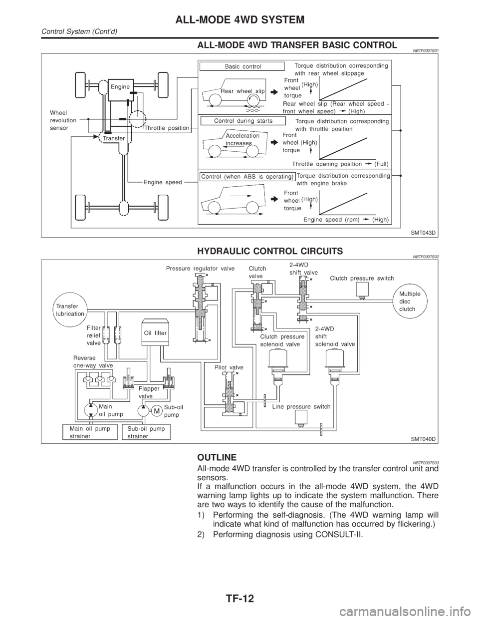
ALL-MODE 4WD TRANSFER BASIC CONTROLNBTF0007S01
SMT043D
HYDRAULIC CONTROL CIRCUITSNBTF0007S02
SMT040D
OUTLINENBTF0007S03All-mode 4WD transfer is controlled by the transfer control unit and
sensors.
If a malfunction occurs in the all-mode 4WD system, the 4WD
warning lamp lights up to indicate the system malfunction. There
are two ways to identify the cause of the malfunction.
1) Performing the self-diagnosis. (The 4WD warning lamp will
indicate what kind of malfunction has occurred by flickering.)
2) Performing diagnosis using CONSULT-II.
ALL-MODE 4WD SYSTEM
Control System (Cont'd)
TF-12
Page 2248 of 2395

CONTROL SYSTEM DIAGRAMNBTF0007S04
SMT763D
INDICATIONS OF 4WD WARNING LAMPNBTF0007S05
Condition Content 4WD warning lamp
During self-diagnosis Indicates the malfunction position by number of flickers. Flickers at malfunction mode.
Lamp check*Checks the lamp by turning ON during engine starting. After
engine starts, it turns OFF if there are no malfunctions.ON
Malfunction in 4WD system*Turns ON to indicate malfunction. When ignition switch is
turned to ªOFFº or the malfunction is corrected, it turns OFF.ON
When vehicle is driven with different
diameters of front and rear tiresFlickers once every 2 seconds.
Turns OFF when ignition switch is ªOFFº.Flickers once every 2 sec-
onds.
High fluid temperature in transfer
unitWhen fluid temperature is high or fluid temperature sensor
circuit is shorted, it flickers twice every second.
It turns OFF when fluid temperature becomes normal.Flickers twice a second.
Other than above (System is nor-
mal.)Lamp is OFF. OFF
*: When 4WD warning lamp is ON, all the 4WD shift indicator lamps turn OFF.
GI
MA
EM
LC
EC
FE
AT
PD
AX
SU
BR
ST
RS
BT
HA
SC
EL
IDX
ALL-MODE 4WD SYSTEM
Control System (Cont'd)
TF-13
Page 2264 of 2395
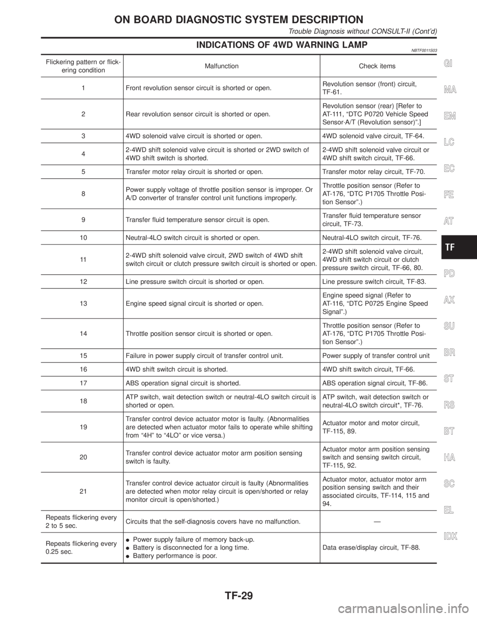
INDICATIONS OF 4WD WARNING LAMPNBTF0011S03
Flickering pattern or flick-
ering conditionMalfunction Check items
1 Front revolution sensor circuit is shorted or open.Revolution sensor (front) circuit,
TF-61.
2 Rear revolution sensor circuit is shorted or open.Revolution sensor (rear) [Refer to
AT-111, ªDTC P0720 Vehicle Speed
Sensor´A/T (Revolution sensor)º.]
3 4WD solenoid valve circuit is shorted or open. 4WD solenoid valve circuit, TF-64.
42-4WD shift solenoid valve circuit is shorted or 2WD switch of
4WD shift switch is shorted.2-4WD shift solenoid valve circuit or
4WD shift switch circuit, TF-66.
5 Transfer motor relay circuit is shorted or open. Transfer motor relay circuit, TF-70.
8Power supply voltage of throttle position sensor is improper. Or
A/D converter of transfer control unit functions improperly.Throttle position sensor (Refer to
AT-176, ªDTC P1705 Throttle Posi-
tion Sensorº.)
9 Transfer fluid temperature sensor circuit is open.Transfer fluid temperature sensor
circuit, TF-73.
10 Neutral-4LO switch circuit is shorted or open. Neutral-4LO switch circuit, TF-76.
112-4WD shift solenoid valve circuit, 2WD switch of 4WD shift
switch circuit or clutch pressure switch circuit is shorted or open.2-4WD shift solenoid valve circuit,
4WD shift switch circuit or clutch
pressure switch circuit, TF-66, 80.
12 Line pressure switch circuit is shorted or open. Line pressure switch circuit, TF-83.
13 Engine speed signal circuit is shorted or open.Engine speed signal (Refer to
AT-116, ªDTC P0725 Engine Speed
Signalº.)
14 Throttle position sensor circuit is shorted or open.Throttle position sensor (Refer to
AT-176, ªDTC P1705 Throttle Posi-
tion Sensorº.)
15 Failure in power supply circuit of transfer control unit. Power supply of transfer control unit
16 4WD shift switch circuit is shorted. 4WD shift switch circuit, TF-66.
17 ABS operation signal circuit is shorted. ABS operation signal circuit, TF-86.
18ATP switch, wait detection switch or neutral-4LO switch circuit is
shorted or open.ATP switch, wait detection switch or
neutral-4LO switch circuit*, TF-76.
19Transfer control device actuator motor is faulty. (Abnormalities
are detected when actuator motor fails to operate while shifting
from ª4Hº to ª4LOº or vice versa.)Actuator motor and motor circuit,
TF-115, 89.
20Transfer control device actuator motor arm position sensing
switch is faulty.Actuator motor arm position sensing
switch and sensing switch circuit,
TF-115, 92.
21Transfer control device actuator circuit is faulty (Abnormalities
are detected when motor relay circuit is open/shorted or relay
monitor circuit is open/shorted.)Actuator motor, actuator motor arm
position sensing switch and their
associated circuits, TF-114, 115 and
94.
Repeats flickering every
2 to 5 sec.Circuits that the self-diagnosis covers have no malfunction. Ð
Repeats flickering every
0.25 sec.IPower supply failure of memory back-up.
IBattery is disconnected for a long time.
IBattery performance is poor.Data erase/display circuit, TF-88.GI
MA
EM
LC
EC
FE
AT
PD
AX
SU
BR
ST
RS
BT
HA
SC
EL
IDX
ON BOARD DIAGNOSTIC SYSTEM DESCRIPTION
Trouble Diagnosis without CONSULT-II (Cont'd)
TF-29