2001 INFINITI QX4 02 sensor
[x] Cancel search: 02 sensorPage 1509 of 2395
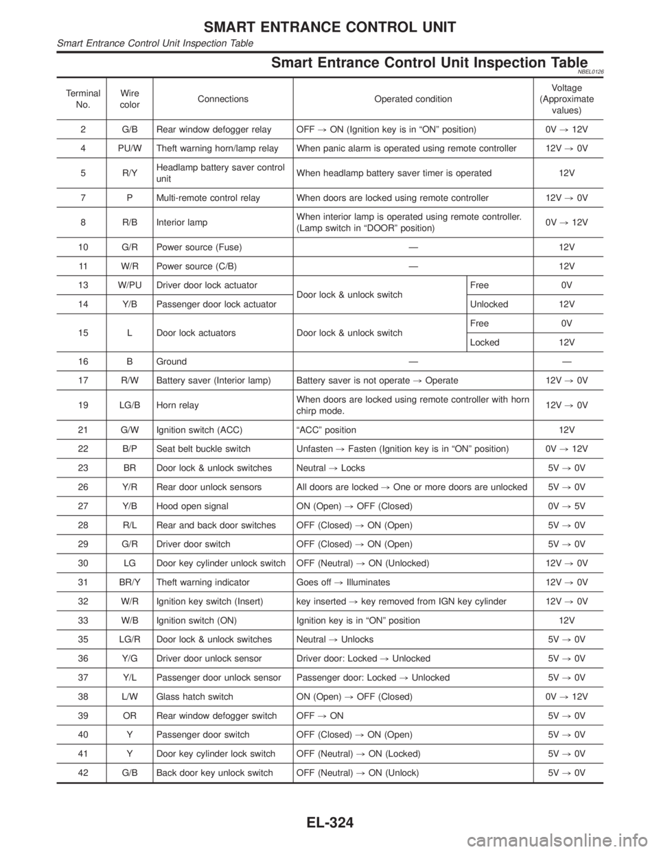
Smart Entrance Control Unit Inspection TableNBEL0126
Terminal
No.Wire
colorConnections Operated conditionVoltage
(Approximate
values)
2 G/B Rear window defogger relay OFF,ON (Ignition key is in ªONº position) 0V,12V
4 PU/W Theft warning horn/lamp relay When panic alarm is operated using remote controller 12V,0V
5 R/YHeadlamp battery saver control
unitWhen headlamp battery saver timer is operated 12V
7 P Multi-remote control relay When doors are locked using remote controller 12V,0V
8 R/B Interior lampWhen interior lamp is operated using remote controller.
(Lamp switch in ªDOORº position)0V,12V
10 G/R Power source (Fuse) Ð 12V
11 W/R Power source (C/B) Ð 12V
13 W/PU Driver door lock actuator
Door lock & unlock switchFree 0V
14 Y/B Passenger door lock actuator Unlocked 12V
15 L Door lock actuators Door lock & unlock switchFree 0V
Locked 12V
16 B Ground Ð Ð
17 R/W Battery saver (Interior lamp) Battery saver is not operate,Operate 12V,0V
19 LG/B Horn relayWhen doors are locked using remote controller with horn
chirp mode.12V,0V
21 G/W Ignition switch (ACC) ªACCº position 12V
22 B/P Seat belt buckle switch Unfasten,Fasten (Ignition key is in ªONº position) 0V,12V
23 BR Door lock & unlock switches Neutral,Locks 5V,0V
26 Y/R Rear door unlock sensors All doors are locked,One or more doors are unlocked 5V,0V
27 Y/B Hood open signal ON (Open),OFF (Closed) 0V,5V
28 R/L Rear and back door switches OFF (Closed),ON (Open) 5V,0V
29 G/R Driver door switch OFF (Closed),ON (Open) 5V,0V
30 LG Door key cylinder unlock switch OFF (Neutral),ON (Unlocked) 12V,0V
31 BR/Y Theft warning indicator Goes off,Illuminates 12V,0V
32 W/R Ignition key switch (Insert) key inserted,key removed from IGN key cylinder 12V,0V
33 W/B Ignition switch (ON) Ignition key is in ªONº position 12V
35 LG/R Door lock & unlock switches Neutral,Unlocks 5V,0V
36 Y/G Driver door unlock sensor Driver door: Locked,Unlocked 5V,0V
37 Y/L Passenger door unlock sensor Passenger door: Locked,Unlocked 5V,0V
38 L/W Glass hatch switch ON (Open),OFF (Closed) 0V,12V
39 OR Rear window defogger switch OFF,ON 5V,0V
40 Y Passenger door switch OFF (Closed),ON (Open) 5V,0V
41 Y Door key cylinder lock switch OFF (Neutral),ON (Locked) 5V,0V
42 G/B Back door key unlock switch OFF (Neutral),ON (Unlock) 5V,0V
SMART ENTRANCE CONTROL UNIT
Smart Entrance Control Unit Inspection Table
EL-324
Page 1537 of 2395
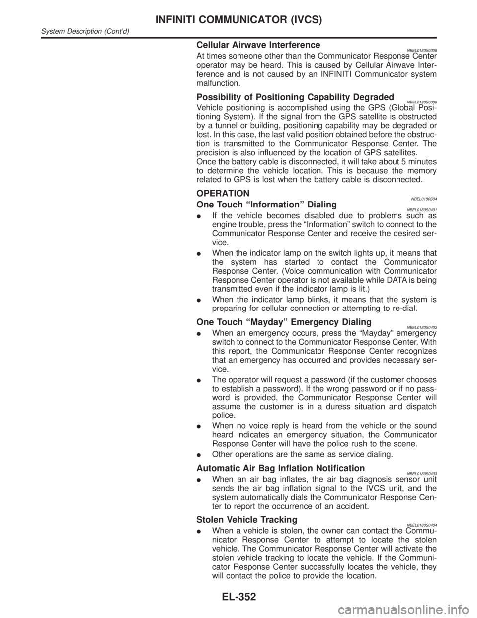
Cellular Airwave InterferenceNBEL0180S0308At times someone other than the Communicator Response Center
operator may be heard. This is caused by Cellular Airwave Inter-
ference and is not caused by an INFINITI Communicator system
malfunction.
Possibility of Positioning Capability DegradedNBEL0180S0309Vehicle positioning is accomplished using the GPS (Global Posi-
tioning System). If the signal from the GPS satellite is obstructed
by a tunnel or building, positioning capability may be degraded or
lost. In this case, the last valid position obtained before the obstruc-
tion is transmitted to the Communicator Response Center. The
precision is also influenced by the location of GPS satellites.
Once the battery cable is disconnected, it will take about 5 minutes
to determine the vehicle location. This is because the memory
related to GPS is lost when the battery cable is disconnected.
OPERATIONNBEL0180S04One Touch ªInformationº DialingNBEL0180S0401IIf the vehicle becomes disabled due to problems such as
engine trouble, press the ªInformationº switch to connect to the
Communicator Response Center and receive the desired ser-
vice.
IWhen the indicator lamp on the switch lights up, it means that
the system has started to contact the Communicator
Response Center. (Voice communication with Communicator
Response Center operator is not available while DATA is being
transmitted even if the indicator lamp is lit.)
IWhen the indicator lamp blinks, it means that the system is
preparing for cellular connection or attempting to re-dial.
One Touch ªMaydayº Emergency DialingNBEL0180S0402IWhen an emergency occurs, press the ªMaydayº emergency
switch to connect to the Communicator Response Center. With
this report, the Communicator Response Center recognizes
that an emergency has occurred and provides necessary ser-
vice.
IThe operator will request a password (if the customer chooses
to establish a password). If the wrong password or if no pass-
word is provided, the Communicator Response Center will
assume the customer is in a duress situation and dispatch
police.
IWhen no voice reply is heard from the vehicle or the sound
heard indicates an emergency situation, the Communicator
Response Center will have the police rush to the scene.
IOther operations are the same as service dialing.
Automatic Air Bag Inflation NotificationNBEL0180S0403IWhen an air bag inflates, the air bag diagnosis sensor unit
sends the air bag inflation signal to the IVCS unit, and the
system automatically dials the Communicator Response Cen-
ter to report the occurrence of an accident.
Stolen Vehicle TrackingNBEL0180S0404IWhen a vehicle is stolen, the owner can contact the Commu-
nicator Response Center to attempt to locate the stolen
vehicle. The Communicator Response Center will activate the
stolen vehicle tracking to locate the vehicle. If the Communi-
cator Response Center successfully locates the vehicle, they
will contact the police to provide the location.
INFINITI COMMUNICATOR (IVCS)
System Description (Cont'd)
EL-352
Page 1554 of 2395
SEL532V
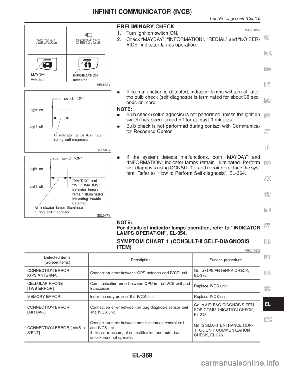
PRELIMINARY CHECKNBEL0184S021. Turn ignition switch ON.
2. Check ªMAYDAYº, ªINFORMATIONº, ªREDIALº and ªNO SER-
VICEº indicator lamps operation.
SEL516V
IIf no malfunction is detected, indicator lamps will turn off after
the bulb check (self-diagnosis) is terminated for about 30 sec-
onds or more.
NOTE:
IBulb check (self-diagnosis) is not performed unless the ignition
switch has been turned off for at least 3 minutes.
IBulb check is not performed during contact with Communica-
tor Response Center.
SEL517V
IIf the system detects malfunctions, both ªMAYDAYº and
ªINFORMATIONº indicator lamps remain illuminated. Perform
self-diagnosis using CONSULT-II and repair or replace the sys-
tem. Refer to ªHow to Perform Self-diagnosisº, EL-364.
NOTE:
For details of indicator lamps operation, refer to ªINDICATOR
LAMPS OPERATIONº, EL-354.
SYMPTOM CHART 1 (CONSULT-II SELF-DIAGNOSIS
ITEM)
NBEL0184S03
Detected items
(Screen items)Description Service procedure
CONNECTION ERROR
[GPS ANTENNA]Connection error between GPS antenna and IVCS unit.Go to GPS ANTENNA CHECK,
EL-376.
CELLULAR PHONE
[TWB ERROR]Communication error between CPU in the IVCS unit and
transceiverReplace IVCS unit.
MEMORY ERROR Inner memory error of the IVCS unit Replace IVCS unit.
CONNECTION ERROR
[AIR BAG]Connection error between air bag diagnosis sensor unit
and IVCS unit.Go to AIR BAG DIAGNOSIS SEN-
SOR COMMUNICATION CHECK,
EL-376.
CONNECTION ERROR [IVMS or
S/ENT]Connection error between smart entrance control unit
and IVCS unit.
If this error occurs, alarm notification and auto door
unlock may not operate.Go to SMART ENTRANCE CON-
TROL UNIT COMMUNICATION
CHECK, EL-376.
GI
MA
EM
LC
EC
FE
AT
TF
PD
AX
SU
BR
ST
RS
BT
HA
SC
IDX
INFINITI COMMUNICATOR (IVCS)
Trouble Diagnoses (Cont'd)
EL-369
Page 1561 of 2395
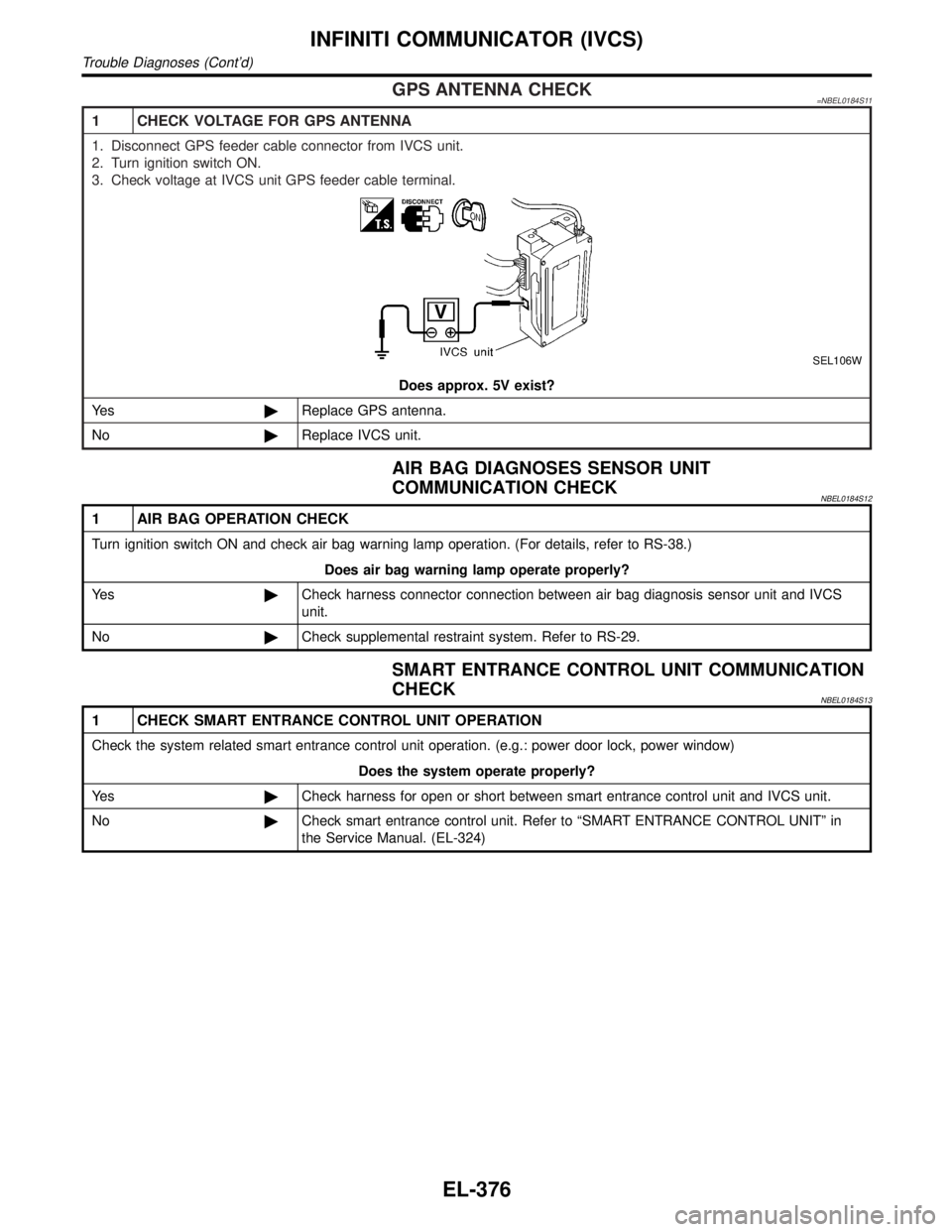
GPS ANTENNA CHECK=NBEL0184S11
1 CHECK VOLTAGE FOR GPS ANTENNA
1. Disconnect GPS feeder cable connector from IVCS unit.
2. Turn ignition switch ON.
3. Check voltage at IVCS unit GPS feeder cable terminal.
SEL106W
Does approx. 5V exist?
Ye s©Replace GPS antenna.
No©Replace IVCS unit.
AIR BAG DIAGNOSES SENSOR UNIT
COMMUNICATION CHECK
NBEL0184S12
1 AIR BAG OPERATION CHECK
Turn ignition switch ON and check air bag warning lamp operation. (For details, refer to RS-38.)
Does air bag warning lamp operate properly?
Ye s©Check harness connector connection between air bag diagnosis sensor unit and IVCS
unit.
No©Check supplemental restraint system. Refer to RS-29.
SMART ENTRANCE CONTROL UNIT COMMUNICATION
CHECK
NBEL0184S13
1 CHECK SMART ENTRANCE CONTROL UNIT OPERATION
Check the system related smart entrance control unit operation. (e.g.: power door lock, power window)
Does the system operate properly?
Ye s©Check harness for open or short between smart entrance control unit and IVCS unit.
No©Check smart entrance control unit. Refer to ªSMART ENTRANCE CONTROL UNITº in
the Service Manual. (EL-324)
INFINITI COMMUNICATOR (IVCS)
Trouble Diagnoses (Cont'd)
EL-376
Page 1571 of 2395
SEL683V
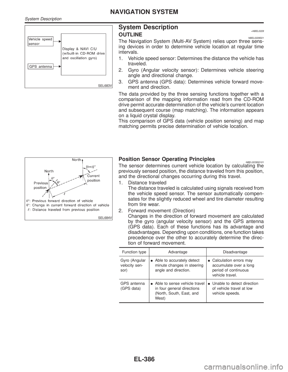
System Description=NBEL0228OUTLINENBEL0228S01The Navigation System (Multi-AV System) relies upon three sens-
ing devices in order to determine vehicle location at regular time
intervals.
1. Vehicle speed sensor: Determines the distance the vehicle has
traveled.
2. Gyro (Angular velocity sensor): Determines vehicle steering
angle and directional change.
3. GPS antenna (GPS data): Determines vehicle forward move-
ment and direction.
The data provided by the three sensing functions together with a
comparison of the mapping information read from the CD-ROM
drive permit accurate determination of the vehicle's current location
and subsequent course (map matching). The information appears
on a liquid crystal display.
This comparison of GPS data (vehicle position sensing) and map
matching permits precise determination of vehicle location.
SEL684V
Position Sensor Operating PrinciplesNBEL0228S0101The sensor determines current vehicle location by calculating the
previously sensed position, the distance traveled from this position,
and the directional changes occurring during this travel.
1. Distance traveled
The distance traveled is calculated using signals received from
the vehicle speed sensor. The sensor automatically compen-
sates for the slightly reduced wheel and tire diameter resulting
from tire wear.
2. Forward movement (Direction)
Changes in the direction of forward movement are calculated
by the gyro (angular velocity sensor) and the GPS antenna
(GPS data). Each of these functions has its advantage and
disadvantages. Depending upon conditions, one function takes
precedence over the other to accurately determine the direc-
tion of forward movement.
Function type Advantage Disadvantage
Gyro (Angular
velocity sen-
sor)IAble to accurately detect
minute changes in steering
angle and direction.ICalculation errors may
accumulate over a long
period of continuous
vehicle travel.
GPS antenna
(GPS data)IAble to sense vehicle travel
in four general directions
(North, South, East, and
West)IUnable to detect direction
of vehicle travel at low
vehicle speeds.
NAVIGATION SYSTEM
System Description
EL-386
Page 1573 of 2395
for example, when the vehicle is in a tunnel, in a parking lot
inside building, under an elevated superhighway or near strong
power lines, the location may not be detected. Turbulent/
electric weather conditions may also affect positioning perfor-
mance. If something is placed on the antenna, the radio wave
from GPS satellites may not be received.
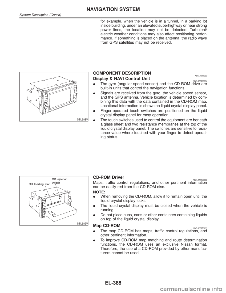
SEL688V
COMPONENT DESCRIPTIONNBEL0228S02Display & NAVI Control UnitNBEL0228S0201IThe gyro (angular speed sensor) and the CD-ROM drive are
built-in units that control the navigation functions.
ISignals are received from the gyro, the vehicle speed sensor,
and the GPS antenna. Vehicle location is determined by com-
bining this data with the data contained in the CD-ROM map.
Locational information is shown on liquid crystal display panel.
IFinger-operated touch switches are positioned on the liquid
crystal display panel for easy operation.
IThe touch switches used to control the equipment are beneath
a glass sheet and two resistance membranes at the top of the
liquid crystal display panel. The switches are sensitive to resis-
tance value where touched with your finger to detect operat-
ing status.
SEL689V
CD-ROM DriverNBEL0228S0202Maps, traffic control regulations, and other pertinent information
can be easily red from the CD-ROM disc.
NOTE:
IWhen removing the CD-ROM, allow it to remain open until the
liquid crystal display locks.
IThe liquid crystal display must be closed when the vehicle is
running.
IDo not place cups, cans or other containers containing liquids
on top of the liquid crystal display.
Map CD-ROMNBEL0228S0203IThe map CD-ROM has maps, traffic control regulations, and
other pertinent information.
ITo improve CD-ROM map matching and route determination
functions, the CD-ROM uses an exclusive Nissan format.
Therefore, the use of a CD-ROM provided by other manufac-
turers cannot be used.
NAVIGATION SYSTEM
System Description (Cont'd)
EL-388
Page 1574 of 2395
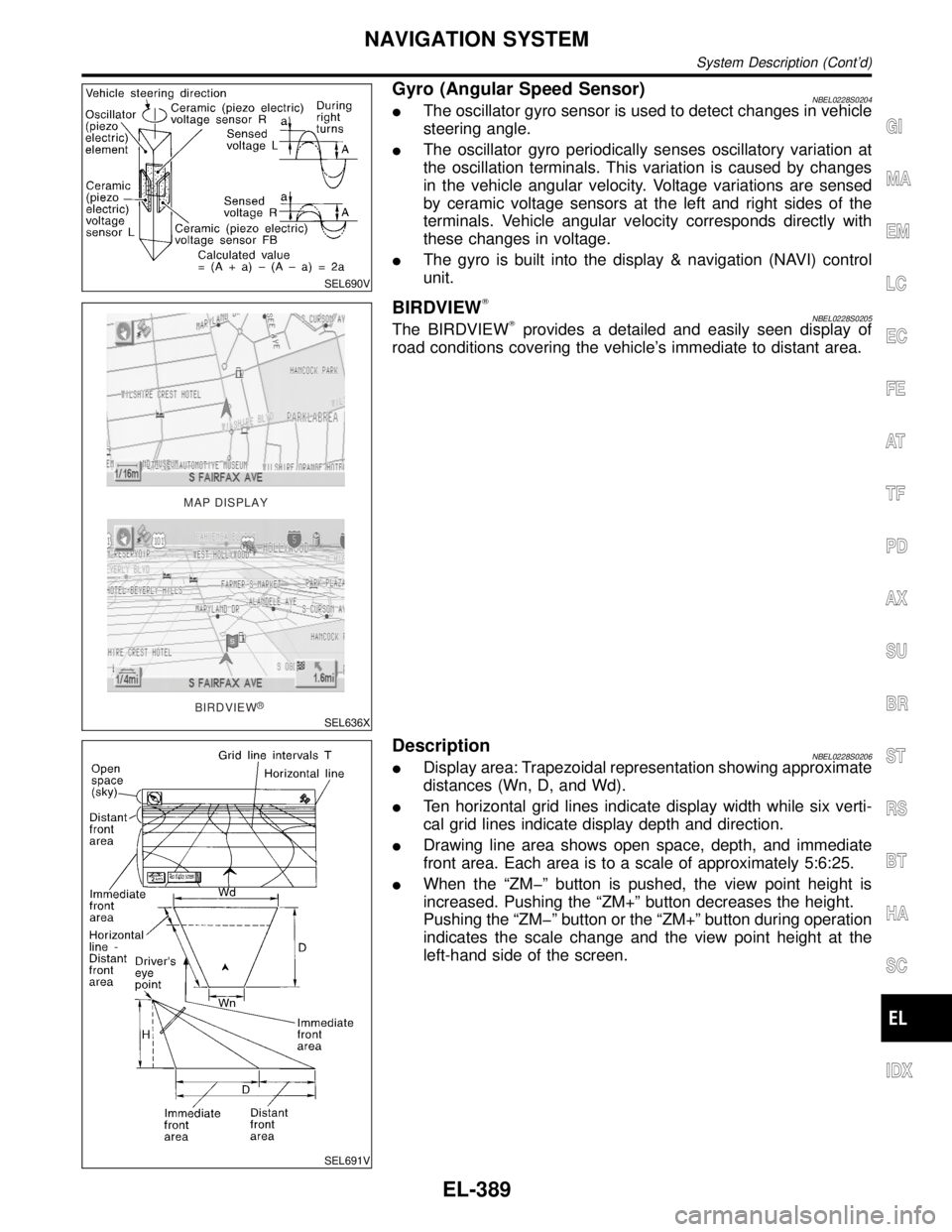
SEL690V
Gyro (Angular Speed Sensor)NBEL0228S0204IThe oscillator gyro sensor is used to detect changes in vehicle
steering angle.
IThe oscillator gyro periodically senses oscillatory variation at
the oscillation terminals. This variation is caused by changes
in the vehicle angular velocity. Voltage variations are sensed
by ceramic voltage sensors at the left and right sides of the
terminals. Vehicle angular velocity corresponds directly with
these changes in voltage.
IThe gyro is built into the display & navigation (NAVI) control
unit.
MAP DISPLAY
BIRDVIEW
R
SEL636X
BIRDVIEWTNBEL0228S0205The BIRDVIEWTprovides a detailed and easily seen display of
road conditions covering the vehicle's immediate to distant area.
SEL691V
DescriptionNBEL0228S0206IDisplay area: Trapezoidal representation showing approximate
distances (Wn, D, and Wd).
ITen horizontal grid lines indicate display width while six verti-
cal grid lines indicate display depth and direction.
IDrawing line area shows open space, depth, and immediate
front area. Each area is to a scale of approximately 5:6:25.
IWhen the ªZMþº button is pushed, the view point height is
increased. Pushing the ªZM+º button decreases the height.
Pushing the ªZMþº button or the ªZM+º button during operation
indicates the scale change and the view point height at the
left-hand side of the screen.
GI
MA
EM
LC
EC
FE
AT
TF
PD
AX
SU
BR
ST
RS
BT
HA
SC
IDX
NAVIGATION SYSTEM
System Description (Cont'd)
EL-389
Page 1587 of 2395
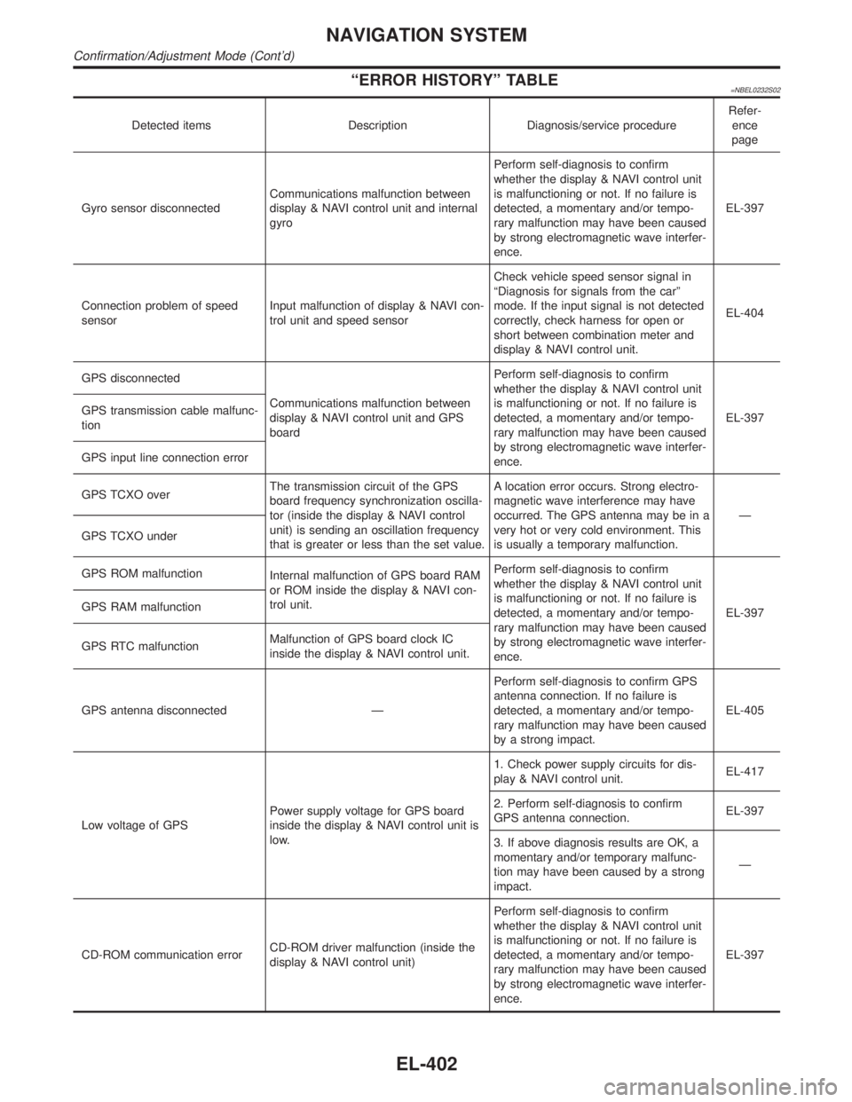
ªERROR HISTORYº TABLE=NBEL0232S02
Detected items Description Diagnosis/service procedureRefer-
ence
page
Gyro sensor disconnectedCommunications malfunction between
display & NAVI control unit and internal
gyroPerform self-diagnosis to confirm
whether the display & NAVI control unit
is malfunctioning or not. If no failure is
detected, a momentary and/or tempo-
rary malfunction may have been caused
by strong electromagnetic wave interfer-
ence.EL-397
Connection problem of speed
sensorInput malfunction of display & NAVI con-
trol unit and speed sensorCheck vehicle speed sensor signal in
ªDiagnosis for signals from the carº
mode. If the input signal is not detected
correctly, check harness for open or
short between combination meter and
display & NAVI control unit.EL-404
GPS disconnected
Communications malfunction between
display & NAVI control unit and GPS
boardPerform self-diagnosis to confirm
whether the display & NAVI control unit
is malfunctioning or not. If no failure is
detected, a momentary and/or tempo-
rary malfunction may have been caused
by strong electromagnetic wave interfer-
ence.EL-397 GPS transmission cable malfunc-
tion
GPS input line connection error
GPS TCXO overThe transmission circuit of the GPS
board frequency synchronization oscilla-
tor (inside the display & NAVI control
unit) is sending an oscillation frequency
that is greater or less than the set value.A location error occurs. Strong electro-
magnetic wave interference may have
occurred. The GPS antenna may be in a
very hot or very cold environment. This
is usually a temporary malfunction.Ð
GPS TCXO under
GPS ROM malfunction
Internal malfunction of GPS board RAM
or ROM inside the display & NAVI con-
trol unit.Perform self-diagnosis to confirm
whether the display & NAVI control unit
is malfunctioning or not. If no failure is
detected, a momentary and/or tempo-
rary malfunction may have been caused
by strong electromagnetic wave interfer-
ence.EL-397 GPS RAM malfunction
GPS RTC malfunctionMalfunction of GPS board clock IC
inside the display & NAVI control unit.
GPS antenna disconnected ÐPerform self-diagnosis to confirm GPS
antenna connection. If no failure is
detected, a momentary and/or tempo-
rary malfunction may have been caused
by a strong impact.EL-405
Low voltage of GPSPower supply voltage for GPS board
inside the display & NAVI control unit is
low.1. Check power supply circuits for dis-
play & NAVI control unit.EL-417
2. Perform self-diagnosis to confirm
GPS antenna connection.EL-397
3. If above diagnosis results are OK, a
momentary and/or temporary malfunc-
tion may have been caused by a strong
impact.Ð
CD-ROM communication errorCD-ROM driver malfunction (inside the
display & NAVI control unit)Perform self-diagnosis to confirm
whether the display & NAVI control unit
is malfunctioning or not. If no failure is
detected, a momentary and/or tempo-
rary malfunction may have been caused
by strong electromagnetic wave interfer-
ence.EL-397
NAVIGATION SYSTEM
Confirmation/Adjustment Mode (Cont'd)
EL-402