2001 INFINITI QX4 02 sensor
[x] Cancel search: 02 sensorPage 1748 of 2395
PrecautionsNBGI0001Observe the following precautions to ensure safe and proper
servicing. These precautions are not described in each indi-
vidual section.
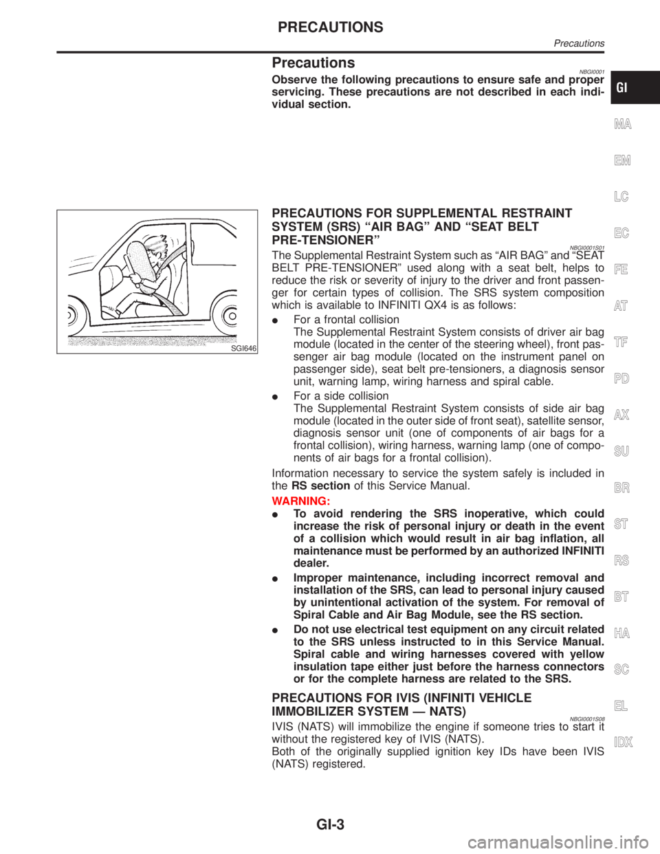
SGI646
PRECAUTIONS FOR SUPPLEMENTAL RESTRAINT
SYSTEM (SRS) ªAIR BAGº AND ªSEAT BELT
PRE-TENSIONERº
NBGI0001S01The Supplemental Restraint System such as ªAIR BAGº and ªSEAT
BELT PRE-TENSIONERº used along with a seat belt, helps to
reduce the risk or severity of injury to the driver and front passen-
ger for certain types of collision. The SRS system composition
which is available to INFINITI QX4 is as follows:
IFor a frontal collision
The Supplemental Restraint System consists of driver air bag
module (located in the center of the steering wheel), front pas-
senger air bag module (located on the instrument panel on
passenger side), seat belt pre-tensioners, a diagnosis sensor
unit, warning lamp, wiring harness and spiral cable.
IFor a side collision
The Supplemental Restraint System consists of side air bag
module (located in the outer side of front seat), satellite sensor,
diagnosis sensor unit (one of components of air bags for a
frontal collision), wiring harness, warning lamp (one of compo-
nents of air bags for a frontal collision).
Information necessary to service the system safely is included in
theRS sectionof this Service Manual.
WARNING:
ITo avoid rendering the SRS inoperative, which could
increase the risk of personal injury or death in the event
of a collision which would result in air bag inflation, all
maintenance must be performed by an authorized INFINITI
dealer.
IImproper maintenance, including incorrect removal and
installation of the SRS, can lead to personal injury caused
by unintentional activation of the system. For removal of
Spiral Cable and Air Bag Module, see the RS section.
IDo not use electrical test equipment on any circuit related
to the SRS unless instructed to in this Service Manual.
Spiral cable and wiring harnesses covered with yellow
insulation tape either just before the harness connectors
or for the complete harness are related to the SRS.
PRECAUTIONS FOR IVIS (INFINITI VEHICLE
IMMOBILIZER SYSTEM Ð NATS)
NBGI0001S08IVIS (NATS) will immobilize the engine if someone tries to start it
without the registered key of IVIS (NATS).
Both of the originally supplied ignition key IDs have been IVIS
(NATS) registered.
MA
EM
LC
EC
FE
AT
TF
PD
AX
SU
BR
ST
RS
BT
HA
SC
EL
IDX
PRECAUTIONS
Precautions
GI-3
Page 1751 of 2395
IClean all disassembled parts in the designated liquid or solvent
prior to inspection or assembly.
IReplace oil seals, gaskets, packings, O-rings, locking washers,
cotter pins, self-locking nuts, etc. with new ones.
IReplace inner and outer races of tapered roller bearings and
needle bearings as a set.
IArrange the disassembled parts in accordance with their
assembled locations and sequence.
IDo not touch the terminals of electrical components which use
microcomputers (such as ECMs).
Static electricity may damage internal electronic components.
IAfter disconnecting vacuum or air hoses, attach a tag to indi-
cate the proper connection.
IUse only the fluids and lubricants specified in this manual.
IUse approved bonding agent, sealants or their equivalents
when required.
IUse tools and recommended special tools where specified for
safe and efficient service repairs.
IWhen repairing the fuel, oil, water, vacuum or exhaust
systems, check all affected lines for leaks.
IDispose of drained oil or the solvent used for cleaning parts in
an appropriate manner.
WARNING:
To prevent ECM from storing the diagnostic trouble codes, do
not carelessly disconnect the harness connectors which are
related to the engine control system and TCM (Transmission
Control Module) system. The connectors should be discon-
nected only when working according to the WORK FLOW of
TROUBLE DIAGNOSES in EC and AT sections.
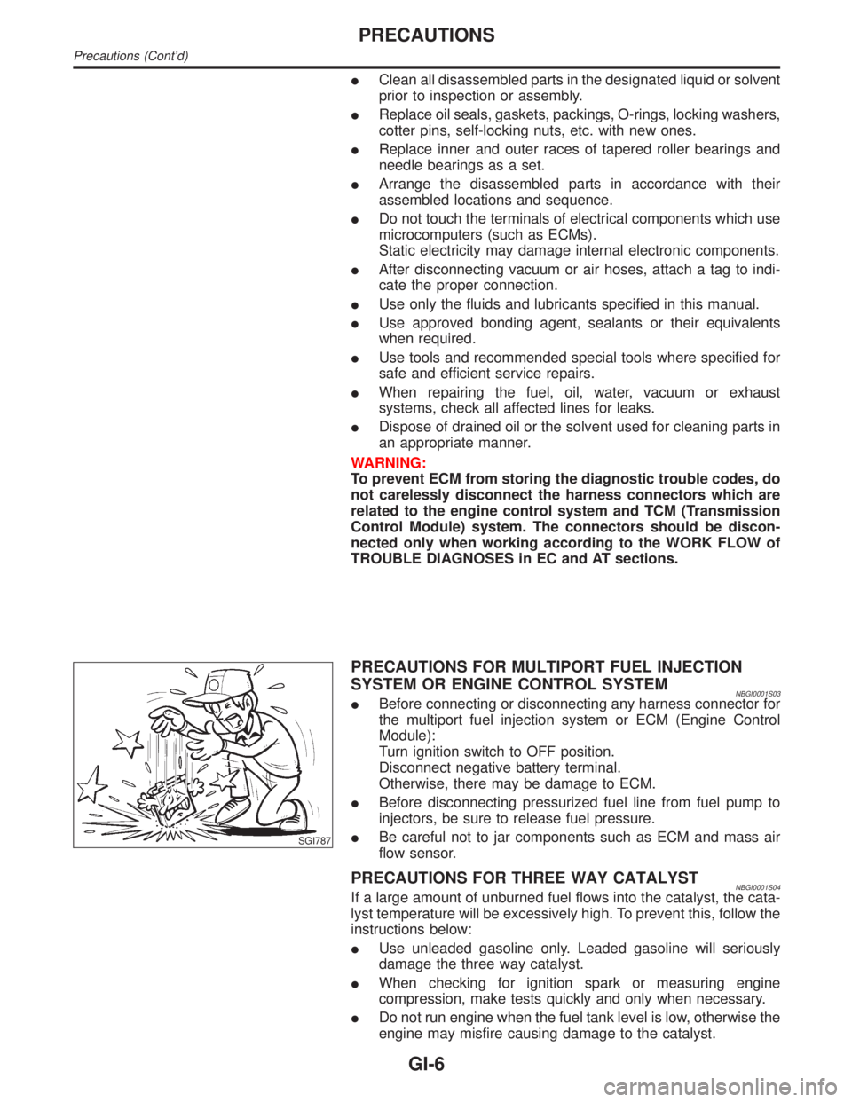
SGI787
PRECAUTIONS FOR MULTIPORT FUEL INJECTION
SYSTEM OR ENGINE CONTROL SYSTEM
NBGI0001S03IBefore connecting or disconnecting any harness connector for
the multiport fuel injection system or ECM (Engine Control
Module):
Turn ignition switch to OFF position.
Disconnect negative battery terminal.
Otherwise, there may be damage to ECM.
IBefore disconnecting pressurized fuel line from fuel pump to
injectors, be sure to release fuel pressure.
IBe careful not to jar components such as ECM and mass air
flow sensor.
PRECAUTIONS FOR THREE WAY CATALYSTNBGI0001S04If a large amount of unburned fuel flows into the catalyst, the cata-
lyst temperature will be excessively high. To prevent this, follow the
instructions below:
IUse unleaded gasoline only. Leaded gasoline will seriously
damage the three way catalyst.
IWhen checking for ignition spark or measuring engine
compression, make tests quickly and only when necessary.
IDo not run engine when the fuel tank level is low, otherwise the
engine may misfire causing damage to the catalyst.
PRECAUTIONS
Precautions (Cont'd)
GI-6
Page 1770 of 2395
Incident Simulation TestsNBGI0004S02INTRODUCTIONNBGI0004S0201Sometimes the symptom is not present when the vehicle is brought
in for service. If possible, re-create the conditions present at the
time of the incident. Doing so may help avoid a No Trouble Found
Diagnosis. The following section illustrates ways to simulate the
conditions/environment under which the owner experiences an
electrical incident.
The section is broken into the six following topics:
IVehicle vibration
IHeat sensitive
IFreezing
IWater intrusion
IElectrical load
ICold or hot start up
Get a thorough description of the incident from the customer. It is
important for simulating the conditions of the problem.
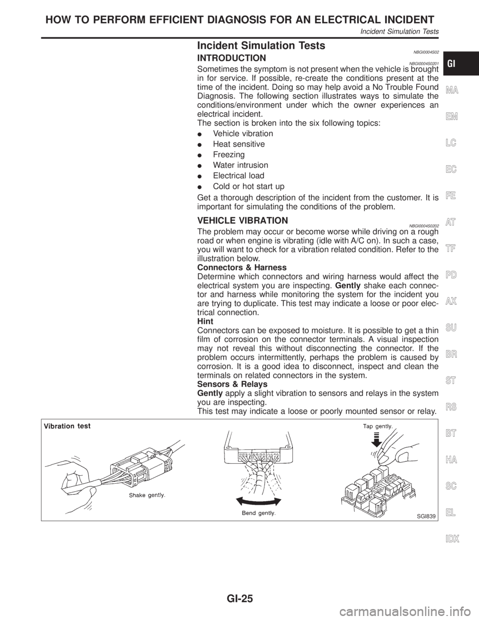
VEHICLE VIBRATIONNBGI0004S0202The problem may occur or become worse while driving on a rough
road or when engine is vibrating (idle with A/C on). In such a case,
you will want to check for a vibration related condition. Refer to the
illustration below.
Connectors & Harness
Determine which connectors and wiring harness would affect the
electrical system you are inspecting.Gentlyshake each connec-
tor and harness while monitoring the system for the incident you
are trying to duplicate. This test may indicate a loose or poor elec-
trical connection.
Hint
Connectors can be exposed to moisture. It is possible to get a thin
film of corrosion on the connector terminals. A visual inspection
may not reveal this without disconnecting the connector. If the
problem occurs intermittently, perhaps the problem is caused by
corrosion. It is a good idea to disconnect, inspect and clean the
terminals on related connectors in the system.
Sensors & Relays
Gentlyapply a slight vibration to sensors and relays in the system
you are inspecting.
This test may indicate a loose or poorly mounted sensor or relay.
SGI839
MA
EM
LC
EC
FE
AT
TF
PD
AX
SU
BR
ST
RS
BT
HA
SC
EL
IDX
HOW TO PERFORM EFFICIENT DIAGNOSIS FOR AN ELECTRICAL INCIDENT
Incident Simulation Tests
GI-25
Page 1796 of 2395
NBGI0010
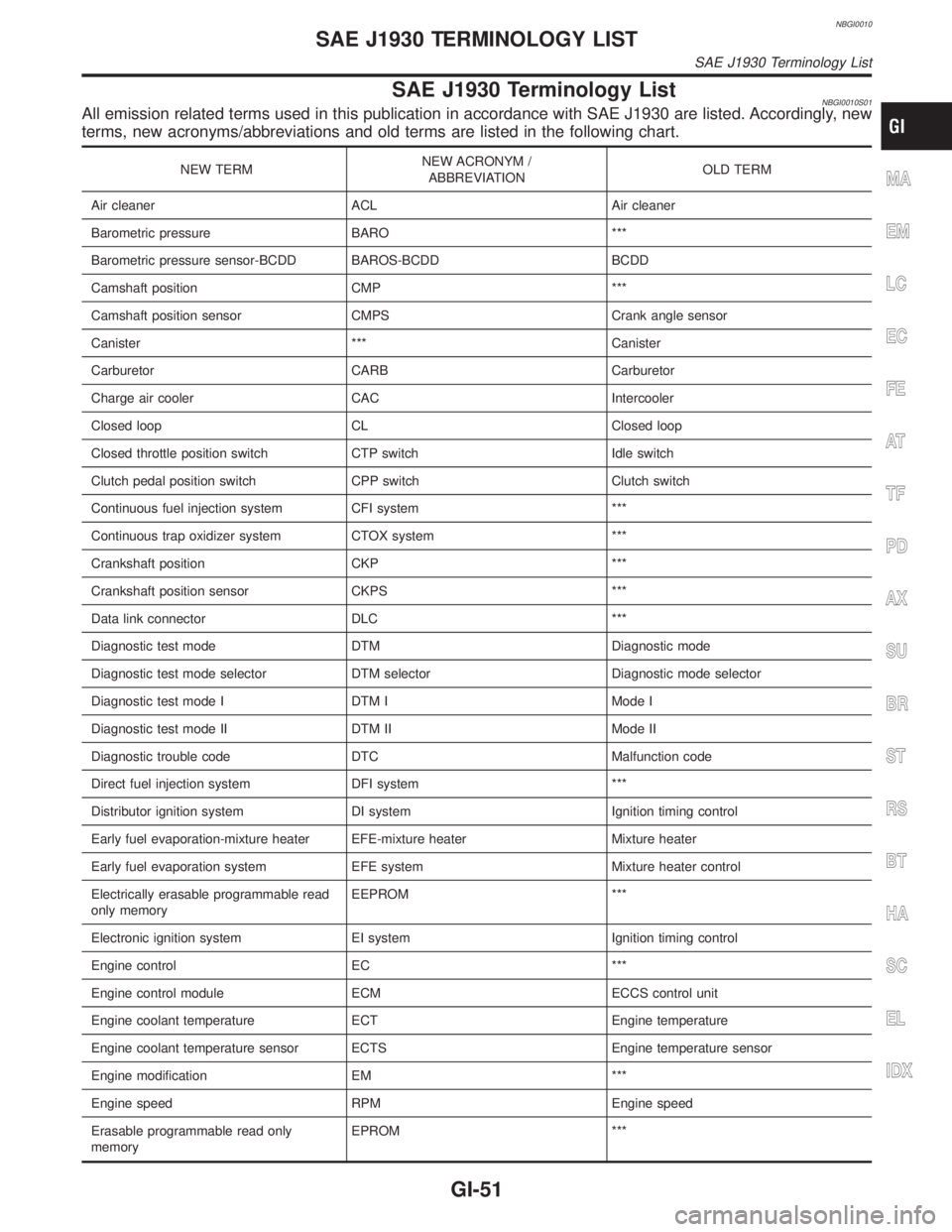
SAE J1930 Terminology ListNBGI0010S01All emission related terms used in this publication in accordance with SAE J1930 are listed. Accordingly, new
terms, new acronyms/abbreviations and old terms are listed in the following chart.
NEW TERMNEW ACRONYM /
ABBREVIATIONOLD TERM
Air cleaner ACL Air cleaner
Barometric pressure BARO ***
Barometric pressure sensor-BCDD BAROS-BCDD BCDD
Camshaft position CMP ***
Camshaft position sensor CMPS Crank angle sensor
Canister *** Canister
Carburetor CARB Carburetor
Charge air cooler CAC Intercooler
Closed loop CL Closed loop
Closed throttle position switch CTP switch Idle switch
Clutch pedal position switch CPP switch Clutch switch
Continuous fuel injection system CFI system ***
Continuous trap oxidizer system CTOX system ***
Crankshaft position CKP ***
Crankshaft position sensor CKPS ***
Data link connector DLC ***
Diagnostic test mode DTM Diagnostic mode
Diagnostic test mode selector DTM selector Diagnostic mode selector
Diagnostic test mode I DTM I Mode I
Diagnostic test mode II DTM II Mode II
Diagnostic trouble code DTC Malfunction code
Direct fuel injection system DFI system ***
Distributor ignition system DI system Ignition timing control
Early fuel evaporation-mixture heater EFE-mixture heater Mixture heater
Early fuel evaporation system EFE system Mixture heater control
Electrically erasable programmable read
only memoryEEPROM ***
Electronic ignition system EI system Ignition timing control
Engine control EC ***
Engine control module ECM ECCS control unit
Engine coolant temperature ECT Engine temperature
Engine coolant temperature sensor ECTS Engine temperature sensor
Engine modification EM ***
Engine speed RPM Engine speed
Erasable programmable read only
memoryEPROM ***MA
EM
LC
EC
FE
AT
TF
PD
AX
SU
BR
ST
RS
BT
HA
SC
EL
IDX
SAE J1930 TERMINOLOGY LIST
SAE J1930 Terminology List
GI-51
Page 1797 of 2395
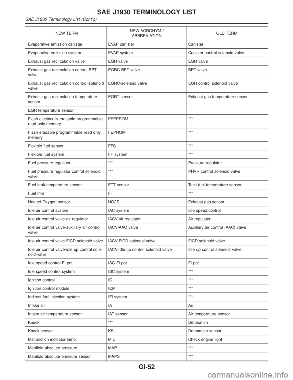
NEW TERMNEW ACRONYM /
ABBREVIATIONOLD TERM
Evaporative emission canister EVAP canister Canister
Evaporative emission system EVAP system Canister control solenoid valve
Exhaust gas recirculation valve EGR valve EGR valve
Exhaust gas recirculation control-BPT
valveEGRC-BPT valve BPT valve
Exhaust gas recirculation control-solenoid
valveEGRC-solenoid valve EGR control solenoid valve
Exhaust gas recirculation temperature
sensorEGRT sensor Exhaust gas temperature sensor
EGR temperature sensor
Flash electrically erasable programmable
read only memoryFEEPROM ***
Flash erasable programmable read only
memoryFEPROM ***
Flexible fuel sensor FFS ***
Flexible fuel system FF system ***
Fuel pressure regulator *** Pressure regulator
Fuel pressure regulator control solenoid
valve*** PRVR control solenoid valve
Fuel tank temperature sensor FTT sensor Tank fuel temperature sensor
Fuel trim FT ***
Heated Oxygen sensor HO2S Exhaust gas sensor
Idle air control system IAC system Idle speed control
Idle air control valve-air regulator IACV-air regulator Air regulator
Idle air control valve-auxiliary air control
valveIACV-AAC valve Auxiliary air control (AAC) valve
Idle air control valve-FICD solenoid valve IACV-FICD solenoid valve FICD solenoid valve
Idle air control valve-idle up control sole-
noid valveIACV-idle up control solenoid valve Idle up control solenoid valve
Idle speed control-FI pot ISC-FI pot FI pot
Idle speed control system ISC system ***
Ignition control IC ***
Ignition control module ICM ***
Indirect fuel injection system IFI system ***
Intake air IA Air
Intake air temperature sensor IAT sensor Air temperature sensor
Knock *** Detonation
Knock sensor KS Detonation sensor
Malfunction indicator lamp MIL Check engine light
Manifold absolute pressure MAP ***
Manifold absolute pressure sensor MAPS ***
SAE J1930 TERMINOLOGY LIST
SAE J1930 Terminology List (Cont'd)
GI-52
Page 1798 of 2395
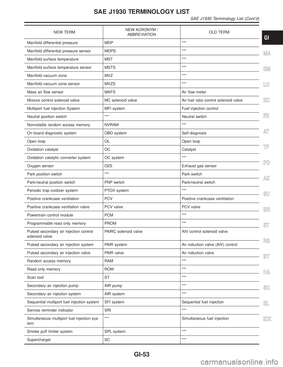
NEW TERMNEW ACRONYM /
ABBREVIATIONOLD TERM
Manifold differential pressure MDP ***
Manifold differential pressure sensor MDPS ***
Manifold surface temperature MST ***
Manifold surface temperature sensor MSTS ***
Manifold vacuum zone MVZ ***
Manifold vacuum zone sensor MVZS ***
Mass air flow sensor MAFS Air flow meter
Mixture control solenoid valve MC solenoid valve Air-fuel ratio control solenoid valve
Multiport fuel injection System MFI system Fuel injection control
Neutral position switch *** Neutral switch
Nonvolatile random access memory NVRAM ***
On board diagnostic system OBD system Self-diagnosis
Open loop OL Open loop
Oxidation catalyst OC Catalyst
Oxidation catalytic converter system OC system ***
Oxygen sensor O2S Exhaust gas sensor
Park position switch *** Park switch
Park/neutral position switch PNP switch Park/neutral switch
Periodic trap oxidizer system PTOX system ***
Positive crankcase ventilation PCV Positive crankcase ventilation
Positive crankcase ventilation valve PCV valve PCV valve
Powertrain control module PCM ***
Programmable read only memory PROM ***
Pulsed secondary air injection control
solenoid valvePAIRC solenoid valve AIV control solenoid valve
Pulsed secondary air injection system PAIR system Air induction valve (AIV) control
Pulsed secondary air injection valve PAIR valve Air induction valve
Random access memory RAM ***
Read only memory ROM ***
Scan tool ST ***
Secondary air injection pump AIR pump ***
Secondary air injection system AIR system ***
Sequential multiport fuel injection system SFI system Sequential fuel injection
Service reminder indicator SRI ***
Simultaneous multiport fuel injection sys-
tem*** Simultaneous fuel injection
Smoke puff limiter system SPL system ***
Supercharger SC ***
MA
EM
LC
EC
FE
AT
TF
PD
AX
SU
BR
ST
RS
BT
HA
SC
EL
IDX
SAE J1930 TERMINOLOGY LIST
SAE J1930 Terminology List (Cont'd)
GI-53
Page 1799 of 2395
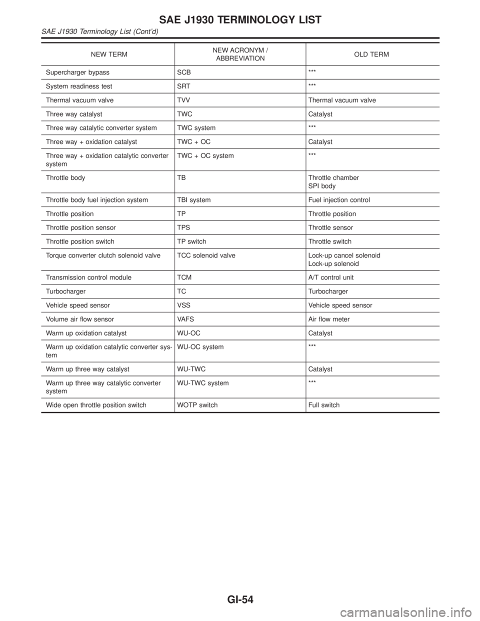
NEW TERMNEW ACRONYM /
ABBREVIATIONOLD TERM
Supercharger bypass SCB ***
System readiness test SRT ***
Thermal vacuum valve TVV Thermal vacuum valve
Three way catalyst TWC Catalyst
Three way catalytic converter system TWC system ***
Three way + oxidation catalyst TWC + OC Catalyst
Three way + oxidation catalytic converter
systemTWC + OC system ***
Throttle body TB Throttle chamber
SPI body
Throttle body fuel injection system TBI system Fuel injection control
Throttle position TP Throttle position
Throttle position sensor TPS Throttle sensor
Throttle position switch TP switch Throttle switch
Torque converter clutch solenoid valve TCC solenoid valve Lock-up cancel solenoid
Lock-up solenoid
Transmission control module TCM A/T control unit
Turbocharger TC Turbocharger
Vehicle speed sensor VSS Vehicle speed sensor
Volume air flow sensor VAFS Air flow meter
Warm up oxidation catalyst WU-OC Catalyst
Warm up oxidation catalytic converter sys-
temWU-OC system ***
Warm up three way catalyst WU-TWC Catalyst
Warm up three way catalytic converter
systemWU-TWC system ***
Wide open throttle position switch WOTP switch Full switch
SAE J1930 TERMINOLOGY LIST
SAE J1930 Terminology List (Cont'd)
GI-54
Page 1800 of 2395

HEATER &
AIR CONDITIONER
SECTION
HA
CONTENTS
PRECAUTIONS...............................................................2
Supplemental Restraint System (SRS)²AIR
BAG²and²SEAT BELT PRE-TENSIONER²...............2
Precautions for Working with HFC-134a (R-134a) .....2
General Refrigerant Precautions .................................3
Precautions for Leak Detection Dye............................3
Identification .................................................................4
Precautions for Refrigerant Connection ......................4
Precautions for Servicing Compressor ........................6
Precautions for Service Equipment .............................7
Wiring Diagrams and Trouble Diagnoses....................9
PREPARATION.............................................................10
Special Service Tools ................................................10
HFC-134a (R-134a) Service Tools and
Equipment .................................................................. 11
DESCRIPTION...............................................................14
Refrigeration System .................................................14
V-6 Variable Displacement Compressor....................15
Component Layout ....................................................19
Introduction ................................................................20
Features .....................................................................20
Overview of Control System ......................................23
Control Operation ......................................................23
Discharge Air Flow.....................................................25
System Description ....................................................26
TROUBLE DIAGNOSES................................................27
Component Location..................................................27
Circuit Diagram (Without Navigation System) ...........30
Wiring Diagram - A/C, A - (Without Navigation
System) ......................................................................31
Circuit Diagram (With Navigation System) ................35
Wiring Diagram - A/C, A - (With Navigation
System) ......................................................................36
Auto Amp. Terminals and Reference Value...............40
Self-diagnosis ............................................................44
How to Perform Trouble Diagnoses for Quick
and Accurate Repair ..................................................65Operational Check .....................................................66
A/C System ................................................................71
Mode Door Motor.......................................................75
Air Mix Door Motor ....................................................82
Intake Door Motor ......................................................87
Blower Motor..............................................................95
Magnet Clutch..........................................................104
Insufficient Cooling .................................................. 112
Insufficient Heating ..................................................121
Noise ........................................................................123
Self-diagnosis ..........................................................124
Memory Function .....................................................126
ECON (ECONOMY) Mode ......................................128
Ambient Sensor Circuit ............................................129
In-vehicle Sensor Circuit..........................................132
Sunload Sensor Circuit ............................................135
Intake Sensor Circuit ...............................................139
Air Mix Door Motor PBR Circuit ..............................141
Multiplex Communication Circuit .............................142
SERVICE PROCEDURE..............................................144
HFC-134a (R-134a) Service Procedure ..................144
Maintenance of Lubricant Quantity in
Compressor .............................................................146
Compressor .............................................................149
Compressor Clutch ..................................................150
Refrigerant Lines .....................................................154
Belt ...........................................................................159
Ventilation Air Filter ..................................................159
SERVICE DATA AND SPECIFICATIONS (SDS).......160
Compressor .............................................................160
Lubricant ..................................................................160
Refrigerant ...............................................................160
Engine Idling Speed (When A/C is ON) ..................160
Belt Tension .............................................................160
GI
MA
EM
LC
EC
FE
AT
TF
PD
AX
SU
BR
ST
RS
BT
SC
EL
IDX