2001 INFINITI QX4 02 sensor
[x] Cancel search: 02 sensorPage 1801 of 2395
Supplemental Restraint System (SRS) ªAIR
BAGº and ªSEAT BELT PRE-TENSIONERº
NBHA0001The Supplemental Restraint System such as ªAIR BAGº and ªSEAT BELT PRE-TENSIONERº used along with
a seat belt, helps to reduce the risk or severity of injury to the driver and front passenger for certain types of
collision. The SRS system composition which is available to INFINITI QX4 is as follows:
IFor a frontal collision
The Supplemental Restraint System consists of driver air bag module (located in the center of the steer-
ing wheel), front passenger air bag module (located on the instrument panel on passenger side), seat belt
pre-tensioners, a diagnosis sensor unit, warning lamp, wiring harness and spiral cable.
IFor a side collision
The Supplemental Restraint System consists of front side air bag module (located in the outer side of front
seat), satellite sensor, diagnosis sensor unit (one of components of air bags for a frontal collision), wiring
harness, warning lamp (one of components of air bags for a frontal collision).
Information necessary to service the system safely is included in theRS sectionof this Service Manual.
WARNING:
ITo avoid rendering the SRS inoperative, which could increase the risk of personal injury or death
in the event of a collision which would result in air bag inflation, all maintenance must be performed
by an authorized INFINITI dealer.
IImproper maintenance, including incorrect removal and installation of the SRS, can lead to per-
sonal injury caused by unintentional activation of the system. For removal of Spiral Cable and Air
Bag Module, see the RS section.
IDo not use electrical test equipment on any circuit related to the SRS unless instructed to in this
Service Manual. Spiral cable and wiring harnesses covered with yellow insulation tape either just
before the harness connectors or for the complete harness are related to the SRS.
Precautions for Working with HFC-134a
(R-134a)
NBHA0002WARNING:
ICFC-12 (R-12) refrigerant and HFC-134a (R-134a) refrigerant are not compatible. If the refrigerants
are mixed and compressor failure is likely to occur, refer to ªCONTAMINATED REFRIGERANTº
below. To determine the purity of HFC-134a (R-134a) in the vehicle and recovery tank, use Refrig-
erant Recovery/Recycling Recharging equipment (ACR4) (J-39500-INF) and Refrigerant Identifier.
IUse only specified lubricant for the HFC-134a (R-134a) A/C system and HFC-134a (R-134a) compo-
nents. If lubricant other than that specified is used, compressor failure is likely to occur.
IThe specified HFC-134a (R-134a) lubricant rapidly absorbs moisture from the atmosphere. The fol-
lowing handling precautions must be observed:
a) When removing refrigerant components from a vehicle, immediately cap (seal) the component to
minimize the entry of moisture from the atmosphere.
b) When installing refrigerant components to a vehicle, do not remove the caps (unseal) until just
before connecting the components. Connect all refrigerant loop components as quickly as pos-
sible to minimize the entry of moisture into system.
c) Only use the specified lubricant from a sealed container. Immediately reseal containers of lubri-
cant. Without proper sealing, lubricant will become moisture saturated and should not be used.
d) Avoid breathing A/C refrigerant and lubricant vapor or mist. Exposure may irritate eyes, nose and
throat. Remove R-134a from the A/C system, using certified service equipment meeting require-
ments of SAE J2210 (R-134a recycling equipment), or J2209 (R-134a recovery equipment). If acci-
dental system discharge occurs, ventilate work area before resuming service. Additional health and
safety information may be obtained from refrigerant and lubricant manufacturers.
e) Do not allow lubricant (Nissan A/C System Oil Type S) to come in contact with styrofoam parts.
Damage may result.
CONTAMINATED REFRIGERANTNBHA0002S01If a refrigerant other than pure R-134a is identified in a vehicle, your options are:
IExplain to the customer that environmental regulations prohibit the release of contaminated refrigerant into
the atmosphere.
IExplain that recovery of the contaminated refrigerant could damage your service equipment and refriger-
ant supply.
PRECAUTIONS
Supplemental Restraint System (SRS) ªAIR BAGº and ªSEAT BELT PRE-TENSIONERº
HA-2
Page 1813 of 2395
Refrigeration System
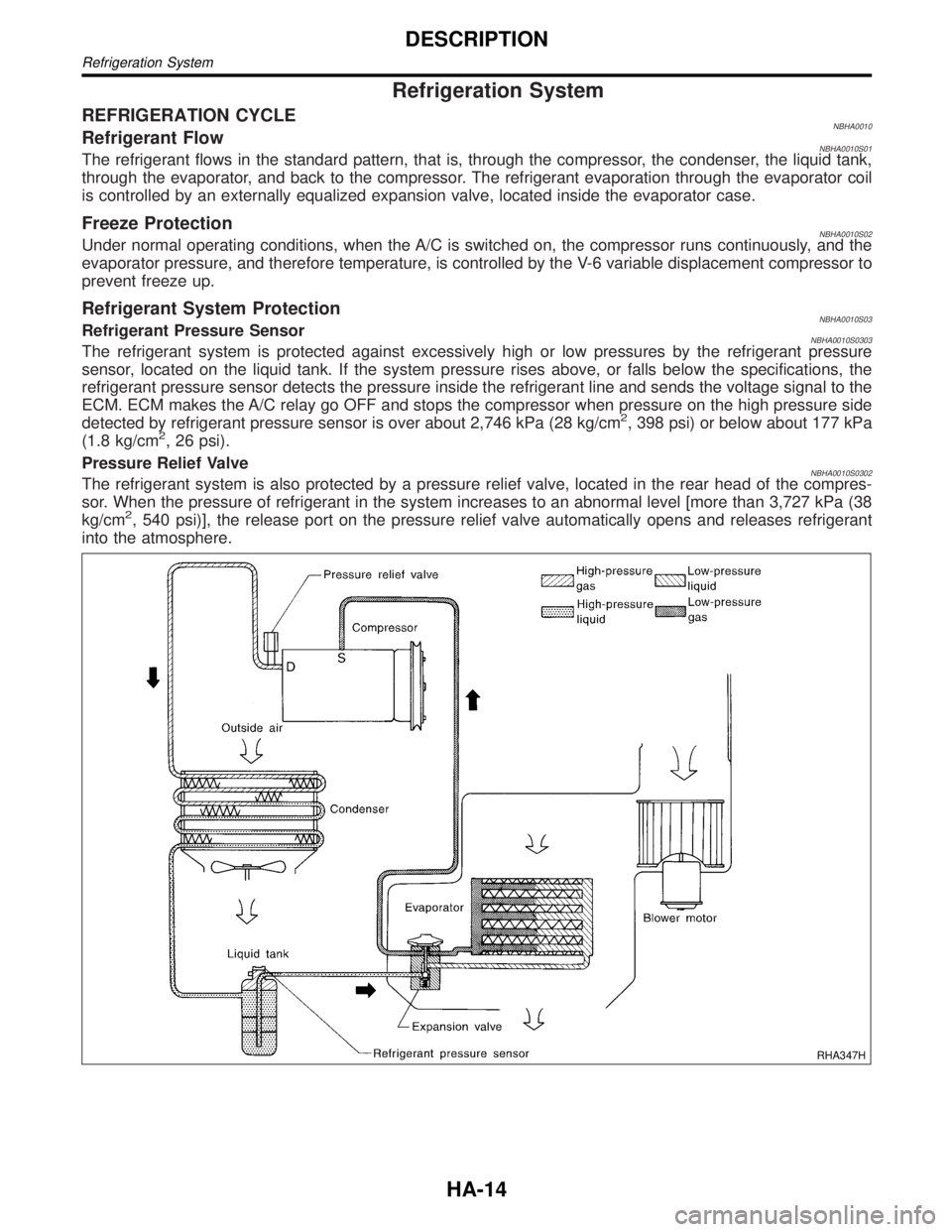
REFRIGERATION CYCLENBHA0010Refrigerant FlowNBHA0010S01The refrigerant flows in the standard pattern, that is, through the compressor, the condenser, the liquid tank,
through the evaporator, and back to the compressor. The refrigerant evaporation through the evaporator coil
is controlled by an externally equalized expansion valve, located inside the evaporator case.
Freeze ProtectionNBHA0010S02Under normal operating conditions, when the A/C is switched on, the compressor runs continuously, and the
evaporator pressure, and therefore temperature, is controlled by the V-6 variable displacement compressor to
prevent freeze up.
Refrigerant System ProtectionNBHA0010S03Refrigerant Pressure SensorNBHA0010S0303The refrigerant system is protected against excessively high or low pressures by the refrigerant pressure
sensor, located on the liquid tank. If the system pressure rises above, or falls below the specifications, the
refrigerant pressure sensor detects the pressure inside the refrigerant line and sends the voltage signal to the
ECM. ECM makes the A/C relay go OFF and stops the compressor when pressure on the high pressure side
detected by refrigerant pressure sensor is over about 2,746 kPa (28 kg/cm
2, 398 psi) or below about 177 kPa
(1.8 kg/cm2, 26 psi).
Pressure Relief Valve
NBHA0010S0302The refrigerant system is also protected by a pressure relief valve, located in the rear head of the compres-
sor. When the pressure of refrigerant in the system increases to an abnormal level [more than 3,727 kPa (38
kg/cm
2, 540 psi)], the release port on the pressure relief valve automatically opens and releases refrigerant
into the atmosphere.
RHA347H
DESCRIPTION
Refrigeration System
HA-14
Page 1819 of 2395
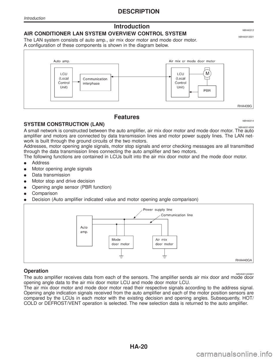
IntroductionNBHA0013AIR CONDITIONER LAN SYSTEM OVERVIEW CONTROL SYSTEMNBHA0013S01The LAN system consists of auto amp., air mix door motor and mode door motor.
A configuration of these components is shown in the diagram below.
RHA439G
FeaturesNBHA0014SYSTEM CONSTRUCTION (LAN)NBHA0014S08A small network is constructed between the auto amplifier, air mix door motor and mode door motor. The auto
amplifier and motors are connected by data transmission lines and motor power supply lines. The LAN net-
work is built through the ground circuits of the two motors.
Addresses, motor opening angle signals, motor stop signals and error checking messages are all transmitted
through the data transmission lines connecting the auto amplifier and two motors.
The following functions are contained in LCUs built into the air mix door motor and the mode door motor.
IAddress
IMotor opening angle signals
IData transmission
IMotor stop and drive decision
IOpening angle sensor (PBR function)
IComparison
IDecision (Auto amplifier indicated value and motor opening angle comparison)
RHA440GA
OperationNBHA0014S0801The auto amplifier receives data from each of the sensors. The amplifier sends air mix door and mode door
opening angle data to the air mix door motor LCU and mode door motor LCU.
The air mix door motor and mode door motor read their respective signals according to the address signal.
Opening angle indication signals received from the auto amplifier and each of the motor position sensors are
compared by the LCUs in each motor with the existing decision and opening angles. Subsequently, HOT/
COLD or DEFROST/VENT operation is selected. The new selection data is returned to the auto amplifier.
DESCRIPTION
Introduction
HA-20
Page 1821 of 2395
Fan Speed ControlNBHA0014S0804Blower speed is automatically controlled based on temperature setting, ambient temperature, in-vehicle
temperature, intake temperature, amount of sunload and air mix door position.
With FAN switch set to ªAUTOº, the blower motor starts to gradually increase air flow volume.
When engine coolant temperature is low, the blower motor operation is delayed to prevent cool air from flow-
ing.
Intake Door ControlNBHA0014S0805The intake doors are automatically controlled by: The temperature setting, ambient temperature, in-vehicle
temperature, intake temperature, amount of sunload and ON-OFF operation of the compressor.
Outlet Door ControlNBHA0014S0806The outlet door is automatically controlled by: The temperature setting, ambient temperature, in-vehicle
temperature, intake temperature and amount of sunload.
Magnet Clutch ControlNBHA0014S0807The ECM controls compressor operation using input signals from the throttle position sensor and auto ampli-
fier.
Self-diagnostic SystemNBHA0014S0808The self-diagnostic system is built into the auto amplifier (LCU) to quickly locate the cause of problems.
DESCRIPTION
Features (Cont'd)
HA-22
Page 1822 of 2395

Overview of Control System=NBHA0015The control system consists of input sensors, switches, the automatic amplifier (microcomputer) and outputs.
The relationship of these components is shown in the diagram below:
RHA856H
Control OperationNBHA0016
RHA452GA
GI
MA
EM
LC
EC
FE
AT
TF
PD
AX
SU
BR
ST
RS
BT
SC
EL
IDX
DESCRIPTION
Overview of Control System
HA-23
Page 1839 of 2395

RHA464GA
RHA858H
Auto Amp. Terminals and Reference ValueNBHA0036INSPECTION OF AUTO AMP.NBHA0036S01IMeasure voltage between each terminal and body ground by
following ªAUTO AMP. INSPECTION TABLEº.
IPin connector terminal layout
RHA839H
AUTO AMP. INSPECTION TABLENBHA0036S02Without Navigation SystemNBHA0036S0201
TERMINAL
NO.ITEM CONDITIONVoltage
V
1 Intake sensor Ð Ð
2 Ambient sensor Ð Ð
3 In-vehicle sensor Ð Ð
6 ECM signal
Compressor: ON Approximately 0
Ccompressor: OFF Approximately 4.6
8 Intake door position switch Intake door positionFRESH Approximately 0
RECIRCULATION or 20%
FRESHApproximately 4.6
11 Sensor ground Ð Approximately 0
12 Sunload sensor Ð Ð
TROUBLE DIAGNOSES
Auto Amp. Terminals and Reference Value
HA-40
Page 1840 of 2395
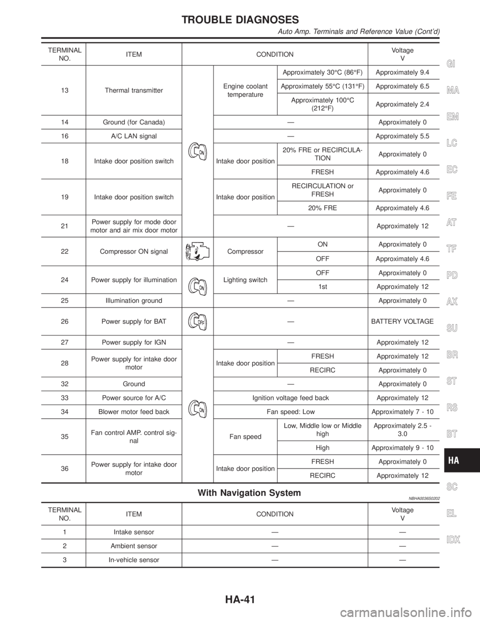
TERMINAL
NO.ITEM CONDITIONVoltage
V
13 Thermal transmitter
Engine coolant
temperatureApproximately 30ÉC (86ÉF) Approximately 9.4
Approximately 55ÉC (131ÉF) Approximately 6.5
Approximately 100ÉC
(212ÉF)Approximately 2.4
14 Ground (for Canada) Ð Approximately 0
16 A/C LAN signal Ð Approximately 5.5
18 Intake door position switch Intake door position20% FRE or RECIRCULA-
TIONApproximately 0
FRESH Approximately 4.6
19 Intake door position switch Intake door positionRECIRCULATION or
FRESHApproximately 0
20% FRE Approximately 4.6
21Power supply for mode door
motor and air mix door motorÐ Approximately 12
22 Compressor ON signal
CompressorON Approximately 0
OFF Approximately 4.6
24 Power supply for illumination
Lighting switchOFF Approximately 0
1st Approximately 12
25 Illumination ground Ð Approximately 0
26 Power supply for BAT
Ð BATTERY VOLTAGE
27 Power supply for IGN
Ð Approximately 12
28Power supply for intake door
motorIntake door positionFRESH Approximately 12
RECIRC Approximately 0
32 Ground Ð Approximately 0
33 Power source for A/C Ignition voltage feed back Approximately 12
34 Blower motor feed back Fan speed: Low Approximately7-10
35Fan control AMP. control sig-
nalFan speedLow, Middle low or Middle
highApproximately 2.5 -
3.0
High Approximately9-10
36Power supply for intake door
motorIntake door positionFRESH Approximately 0
RECIRC Approximately 12
With Navigation SystemNBHA0036S0202
TERMINAL
NO.ITEM CONDITIONVoltage
V
1 Intake sensor Ð Ð
2 Ambient sensor Ð Ð
3 In-vehicle sensor Ð Ð
GI
MA
EM
LC
EC
FE
AT
TF
PD
AX
SU
BR
ST
RS
BT
SC
EL
IDX
TROUBLE DIAGNOSES
Auto Amp. Terminals and Reference Value (Cont'd)
HA-41
Page 1841 of 2395
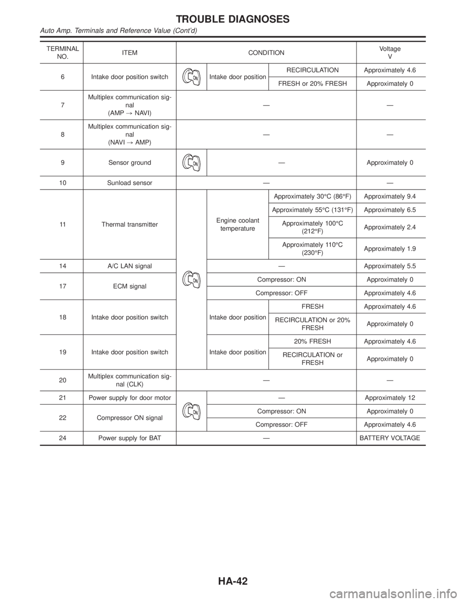
TERMINAL
NO.ITEM CONDITIONVoltage
V
6 Intake door position switch
Intake door positionRECIRCULATION Approximately 4.6
FRESH or 20% FRESH Approximately 0
7Multiplex communication sig-
nal
(AMP,NAVI)ÐÐ
8Multiplex communication sig-
nal
(NAVI,AMP)ÐÐ
9 Sensor ground
Ð Approximately 0
10 Sunload sensor Ð Ð
11 Thermal transmitter
Engine coolant
temperatureApproximately 30ÉC (86ÉF) Approximately 9.4
Approximately 55ÉC (131ÉF) Approximately 6.5
Approximately 100ÉC
(212ÉF)Approximately 2.4
Approximately 110ÉC
(230ÉF)Approximately 1.9
14 A/C LAN signal Ð Approximately 5.5
17 ECM signalCompressor: ON Approximately 0
Compressor: OFF Approximately 4.6
18 Intake door position switch Intake door positionFRESH Approximately 4.6
RECIRCULATION or 20%
FRESHApproximately 0
19 Intake door position switch Intake door position20% FRESH Approximately 4.6
RECIRCULATION or
FRESHApproximately 0
20Multiplex communication sig-
nal (CLK)ÐÐ
21 Power supply for door motor
Ð Approximately 12
22 Compressor ON signalCompressor: ON Approximately 0
Compressor: OFF Approximately 4.6
24 Power supply for BAT Ð BATTERY VOLTAGE
TROUBLE DIAGNOSES
Auto Amp. Terminals and Reference Value (Cont'd)
HA-42