Page 1934 of 2395

RHA060GB
COMPONENT INSPECTIONNBHA0045In-vehicle SensorNBHA0045S01After disconnecting in-vehicle sensor harness connector, measure
resistance between terminals 1 and 2 at sensor harness side, using
the table below.
Temperature ÉC (ÉF) Resistance kW
þ15 (5) 12.73
þ10 (14) 9.92
þ5 (23) 7.80
0 (32) 6.19
5 (41) 4.95
10 (50) 3.99
15 (59) 3.24
20 (68) 2.65
25 (77) 2.19
30 (86) 1.81
35 (95) 1.51
40 (104) 1.27
45 (113) 1.07
If NG, replace in-vehicle sensor.
RHA639F
Sunload Sensor Circuit
COMPONENT DESCRIPTIONNBHA0046The sunload sensor is located on the right defroster grille. It detects
sunload entering through windshield by means of a photo diode.
The sensor converts the sunload into a current value which is then
input into the auto amplifier.
SUNLOAD INPUT PROCESSNBHA0047The auto amp. also includes a processing circuit which ªaverageº
the variations in detected sunload over a period of time. This pre-
vents drastic swings in the ATC system operation due to small or
quick variations in detected sunload.
For example, consider driving along a road bordered by an occa-
sional group of large trees. The sunload detected by the sunload
sensor will vary whenever the trees obstruct the sunlight. The pro-
cessing circuit averages the detected sunload over a period of
time, so that the (insignificant) effect of the trees momentarily
GI
MA
EM
LC
EC
FE
AT
TF
PD
AX
SU
BR
ST
RS
BT
SC
EL
IDX
TROUBLE DIAGNOSES
In-vehicle Sensor Circuit (Cont'd)
HA-135
Page 1935 of 2395
obstructing the sunlight does not cause any change in the ATC
system operation. On the other hand, shortly after entering a long
tunnel, the system will recognize the change in sunload, and the
system will react accordingly.
SHA301FA
DIAGNOSTIC PROCEDURENBHA0048SYMPTOM: Sunload sensor circuit is open or shorted. (or
þ
is indicated on the display as a result of conducting Self-
diagnosis STEP 2.)
1 CHECK SUNLOAD SENSOR CIRCUIT BETWEEN SUNLOAD SENSOR AND BODY GROUND
Disconnect sunload sensor harness connector.
Do approx. 5 volts exist between sunload sensor harness terminal No. 1 and body ground?
RHA062G
YesorNo
Ye s©GO TO 2.
No©GO TO 4.
TROUBLE DIAGNOSES
Sunload Sensor Circuit (Cont'd)
HA-136
Page 1936 of 2395
2 CHECK SUNLOAD SENSOR CIRCUIT BETWEEN SUNLOAD SENSOR AND AUTO AMP. (LCU)
1. Disconnect auto amp. (LCU) harness connector.
2. Check circuit continuity between sunload sensor harness terminal No. 2 and auto amp. (LCU) harness terminal No. 11
or 9.
RHA833H
Continuity should exist.
If OK, check harness for short.
OK or NG
OK©GO TO 3.
NG©Repair harness or connector.
3 CHECK SUNLOAD SENSOR.
Refer to HA-138.
OK or NG
OK©1. Replace auto amp. (LCU).
2. Go to self-diagnosis step-by-step procedure (HA-45) and perform self-diagnosis STEP
2.
Confirm that code No. 20 is displayed.
NG©1. Replace sunload sensor.
2. Go to self-diagnosis step-by-step procedure (HA-45) and perform self-diagnosis STEP
2.
Confirm that code No. 20 is displayed.
GI
MA
EM
LC
EC
FE
AT
TF
PD
AX
SU
BR
ST
RS
BT
SC
EL
IDX
TROUBLE DIAGNOSES
Sunload Sensor Circuit (Cont'd)
HA-137
Page 1937 of 2395
4 CHECK SUNLOAD SENSOR CIRCUIT BETWEEN SUNLOAD SENSOR AND AUTO AMP. (LCU)
1. Disconnect auto amp. (LCU) harness connector.
2. Check circuit continuity between sunload sensor harness terminal No. 1 and auto amp. (LCU) harness terminal No. 12
or 10.
RHA834H
Continuity should exist.
If OK, check harness for short.
OK or NG
OK©1. Replace auto amp.
2. Go to self-diagnosis step-by-step procedure (HA-45) and perform self-diagnosis STEP
2.
Confirm that code No. 20 is displayed.
NG©Repair harness or connector.
RHA835H
COMPONENT INSPECTIONNBHA0049Sunload SensorNBHA0049S01Measure voltage between auto amp. terminal 12 (10) and body
ground.
If NG, replace sunload sensor.
IWhen checking sunload sensor, select a place where sun
shines directly on it.
TROUBLE DIAGNOSES
Sunload Sensor Circuit (Cont'd)
HA-138
Page 1938 of 2395
SHA930E
RHA584E
Intake Sensor Circuit
COMPONENT DESCRIPTIONNBHA0105Intake SensorNBHA0105S01The intake sensor is located on the cooling unit. It converts tem-
perature of air after it passes through the evaporator into a resis-
tance value which is then input to the auto amp.
After disconnecting intake sensor harness connector, measure
resistance between terminals 1 and 2 at sensor harness side, using
the table below.
Temperature ÉC (ÉF) Resistance kW
þ15 (5) 12.73
þ10 (14) 9.92
þ5 (23) 7.80
0 (32) 6.19
5 (41) 4.95
10 (50) 3.99
15 (59) 3.24
20 (68) 2.65
25 (77) 2.19
30 (86) 1.81
35 (95) 1.51
40 (104) 1.27
45 (113) 1.07
If NG, replace intake sensor.
GI
MA
EM
LC
EC
FE
AT
TF
PD
AX
SU
BR
ST
RS
BT
SC
EL
IDX
TROUBLE DIAGNOSES
Sunload Sensor Circuit (Cont'd)
HA-139
Page 1939 of 2395
RHA056GI
DIAGNOSTIC PROCEDURENBHA0106SYMPTOM: Intake sensor circuit is open or shorted. (or
þ
is indicated on the display as a result of conducting
Self-diagnosis STEP 2.)
1 CHECK INTAKE SENSOR CIRCUIT BETWEEN INTAKE SENSOR AND BODY GROUND
Disconnect intake sensor harness connector.
Do approx. 5 volts exist between intake sensor harness terminal No. 2 and body ground?
RHA495G
YesorNo
Ye s©GO TO 2.
No©GO TO 4.
2 CHECK INTAKE SENSOR CIRCUIT BETWEEN INTAKE SENSOR AND AUTO AMP. (LCU)
1. Disconnect auto amp. (LCU) harness connector.
2. Check circuit continuity between intake sensor harness terminal No. 2 and auto amp. (LCU) harness terminal No. 11 or
9.
RHA836H
Continuity should exist.
If OK, check harness for short.
OK or NG
OK©GO TO 3.
NG©Repair harness or connector.
TROUBLE DIAGNOSES
Intake Sensor Circuit (Cont'd)
HA-140
Page 1940 of 2395

3 CHECK INTAKE SENSOR
Refer to HA-139.
OK or NG
OK©1. Replace auto amp.
2. Go to self-diagnosis step-by-step procedure (HA-45) and perform self-diagnosis STEP
2.
Confirm that code No. 20 is displayed.
NG©1. Replace intake sensor.
2. Go to self-diagnosis step-by-step procedure (HA-45) and perform self-diagnosis STEP
2.
Confirm that code No. 20 is displayed.
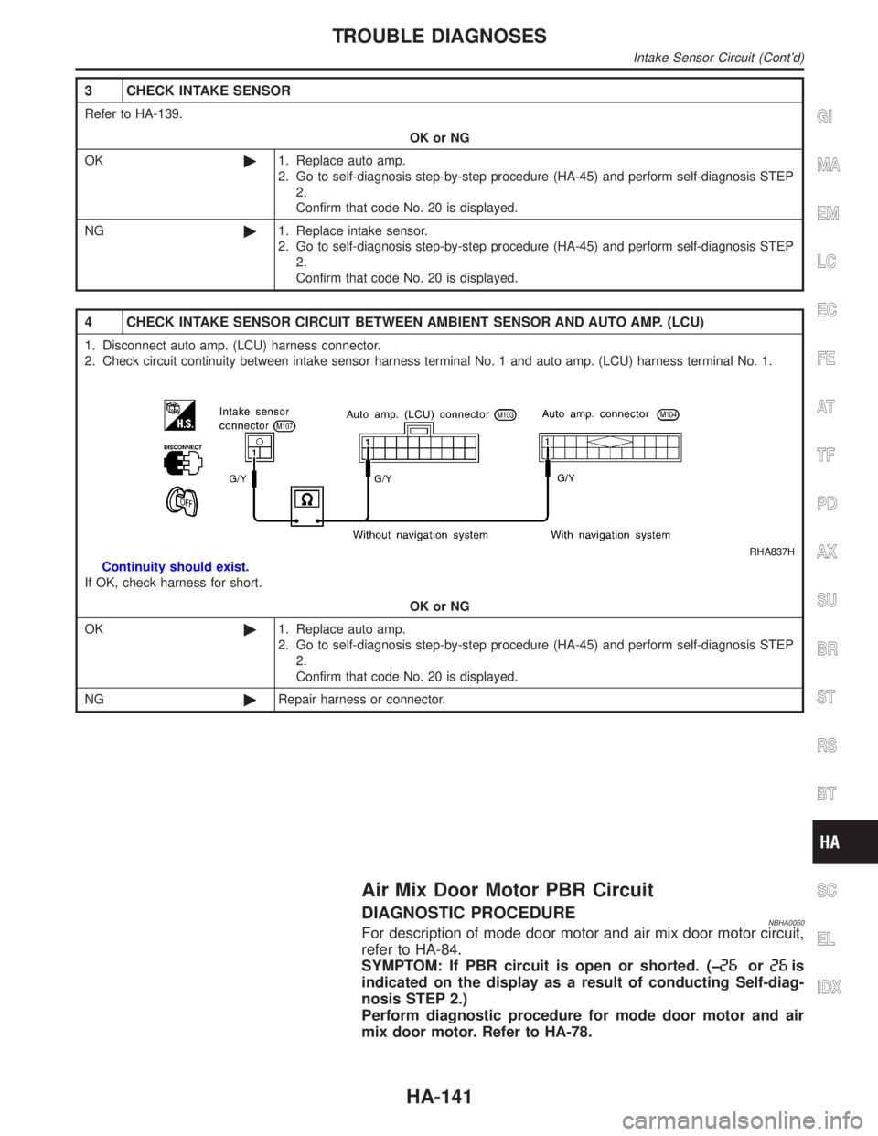
4 CHECK INTAKE SENSOR CIRCUIT BETWEEN AMBIENT SENSOR AND AUTO AMP. (LCU)
1. Disconnect auto amp. (LCU) harness connector.
2. Check circuit continuity between intake sensor harness terminal No. 1 and auto amp. (LCU) harness terminal No. 1.
RHA837H
Continuity should exist.
If OK, check harness for short.
OK or NG
OK©1. Replace auto amp.
2. Go to self-diagnosis step-by-step procedure (HA-45) and perform self-diagnosis STEP
2.
Confirm that code No. 20 is displayed.
NG©Repair harness or connector.
Air Mix Door Motor PBR Circuit
DIAGNOSTIC PROCEDURENBHA0050For description of mode door motor and air mix door motor circuit,
refer to HA-84.
SYMPTOM: If PBR circuit is open or shorted. (þ
oris
indicated on the display as a result of conducting Self-diag-
nosis STEP 2.)
Perform diagnostic procedure for mode door motor and air
mix door motor. Refer to HA-78.
GI
MA
EM
LC
EC
FE
AT
TF
PD
AX
SU
BR
ST
RS
BT
SC
EL
IDX
TROUBLE DIAGNOSES
Intake Sensor Circuit (Cont'd)
HA-141
Page 1954 of 2395

CHECKING FOR REFRIGERANT LEAKS=NBHA0078IPerform a visual inspection of all refrigeration parts, fittings,
hoses and components for signs of A/C lubricant leakage,
damage and corrosion. A/C lubricant leakage may indicate an
area of refrigerant leakage. Allow extra inspection time in these
areas when using either an electronic refrigerant leak detector
or fluorescent dye leak detector.
IIf dye is observed, confirm the leak with an electronic refriger-
ant leak detector. It is possible a prior leak was repaired and
not properly cleaned.
IWhen searching for leaks, do not stop when one leak is found
but continue to check for additional leaks at all system compo-
nents and connections.
IWhen searching for refrigerant leaks using an electronic leak
detector, move the probe along the suspected leak area at 1
to 2 inches per second and no further than 1/4 inch from the
component.
NOTE:
Moving the electronic leak detector probe slower and closer to
the suspected leak area will improve the chances of finding a
leak.
CHECKING SYSTEM FOR LEAKS USING THE
FLUORESCENT LEAK DETECTOR
NBHA01161. Check A/C system for leaks using the UV lamp and safety
glasses (J-42220) in a low sunlight area (area without windows
preferable). Illuminate all components, fittings and lines. The
dye will appear as a bright green/yellow area at the point of
leakage. Fluorescent dye observed at the evaporator drain
opening indicates an evaporator core assembly (tubes, core or
TXV) leak.
2. If the suspected area is difficult to see, use an adjustable mir-
ror or wipe the area with a clean shop rag or cloth, then check
the cloth with the UV lamp for dye residue.
3. After the leak is repaired, remove any residual dye using dye
cleaner (J-43872) to prevent future misdiagnosis.
4. Perform a system performance check and verify the leak repair
with an approved electronic refrigerant leak detector.
NOTE:
IOther gases in the work area or substances on the A/C
components, for example, anti-freeze, windshield washer
fluid, solvents and lubricants, may falsely trigger the leak
detector. Make sure the surfaces to be checked are clean.
Clean with a dry cloth or blow off with shop air.
IDo not allow the sensor tip of the detector to contact with
any substance. This can also cause false readings and
may damage the detector.
DYE INJECTIONNBHA0117(This procedure is only necessary when re-charging the system or
when the compressor has seized and was replaced.)
1. Check A/C system static (at rest) Pressure. Pressure must be
at least 345 kPa (50 psi).
2. Pour one bottle (1/4 ounce /7.4 cc) of the A/C refrigerant dye
into the injector tool (J-41459).
3. Connect the injector tool to the A/C LOW PRESSURE side
service fitting.
4. Start engine and switch A/C ON.
GI
MA
EM
LC
EC
FE
AT
TF
PD
AX
SU
BR
ST
RS
BT
SC
EL
IDX
SERVICE PROCEDURE
Refrigerant Lines (Cont'd)
HA-155