Page 1098 of 2395

SEF355X
Overall Function CheckNBEC0336Use this procedure to check the overall monitoring function of the
EVAP control system purge flow monitoring. During this check, a
1st trip DTC might not be confirmed.
WITH GSTNBEC0336S011) Lift up drive wheels.
2) Start engine (TCS switch ªOFFº) and warm it up to normal
operating temperature.
3) Turn ignition switch ªOFFº, wait at least 10 seconds.
4) Start engine and wait at least 70 seconds.
5) Set voltmeter probes to ECM terminals 84 (EVAP control sys-
tem pressure sensor signal) and ground.
6) Check EVAP control system pressure sensor value at idle
speed and note it.
7) Establish and maintain the following conditions for at least 1
minute.
Air conditioner switch ON
Steering wheel Fully turned
Headlamp switch ON
Rear window defogger switch ON
Engine speed Approx. 3,000 rpm
Gear position Any position other than ªPº, ªNº or ªRº
8) Verify that EVAP control system pressure sensor value stays
0.1V less than the value at idle speed (measured at step 6) for
at least 1 second.
9) If NG, go to ªDiagnostic Procedureº, EC-564.
GI
MA
EM
LC
FE
AT
TF
PD
AX
SU
BR
ST
RS
BT
HA
SC
EL
IDX
DTC P1447 EVAPORATIVE EMISSION (EVAP) CONTROL SYSTEM PURGE
FLOW MONITORING
Overall Function Check
EC-563
Page 1099 of 2395
Diagnostic Procedure=NBEC0337
1 CHECK EVAP CANISTER
1. Turn ignition switch ªOFFº.
2. Check EVAP canister for cracks.
OK or NG
OK (With CONSULT-II)©GO TO 2.
OK (Without CONSULT-
II)©GO TO 3.
NG©Replace EVAP canister.
2 CHECK PURGE FLOW
With CONSULT-II
1. Disconnect vacuum hose connected to EVAP canister purge volume control solenoid valve at EVAP service port and
install vacuum gauge.
SEF983Y
2. Start engine and let it idle.
3. Select ªPURG VOL CONT/Vº in ªACTIVE TESTº mode with CONSULT-II.
4. Rev engine up to 2,000 rpm.
5. Touch ªQdº and ªQuº on CONSULT-II screen to adjust ªPURG VOL CONT/Vº opening and check vacuum existence.
SEF012Z
OK or NG
OK©GO TO 7.
NG©GO TO 4.
DTC P1447 EVAPORATIVE EMISSION (EVAP) CONTROL SYSTEM PURGE
FLOW MONITORING
Diagnostic Procedure
EC-564
Page 1100 of 2395
3 CHECK PURGE FLOW
Without CONSULT-II
1. Start engine and warm it up to normal operating temperature.
2. Stop engine.
3. Disconnect vacuum hose connected to EVAP canister purge volume control solenoid valve at EVAP service port and
install vacuum gauge.
SEF983Y
4. Start engine and let it idle for at least 80 seconds.
5. Check vacuum gauge indication when revving engine up to 2,000 rpm.
Vacuum should exist.
6. Release the accelerator pedal fully and let idle.
Vacuum should not exist.
OK or NG
OK©GO TO 7.
NG©GO TO 4.
4 CHECK EVAP PURGE LINE
1. Turn ignition switch ªOFFº.
2. Check EVAP purge line for improper connection or disconnection.
Refer to ªEVAPORATIVE EMISSION LINE DRAWINGº, EC-36.
OK or NG
OK (With CONSULT-II)©GO TO 5.
OK (Without CONSULT-
II)©GO TO 6.
NG©Repair it.
GI
MA
EM
LC
FE
AT
TF
PD
AX
SU
BR
ST
RS
BT
HA
SC
EL
IDX
DTC P1447 EVAPORATIVE EMISSION (EVAP) CONTROL SYSTEM PURGE
FLOW MONITORING
Diagnostic Procedure (Cont'd)
EC-565
Page 1101 of 2395
5 CHECK EVAP PURGE HOSE AND PURGE PORT
1. Disconnect purge hoses connected to EVAP service portAand EVAP canister purge volume control solenoid valveB.
SEF367U
2. Blow air into each hose and EVAP purge portC.
3. Check that air flows freely.
SEF368U
OK or NG
OK©GO TO 6.
NG©Repair or clean hoses and/or purge port.
6 CHECK EVAP CANISTER PURGE VOLUME CONTROL SOLENOID VALVE
With CONSULT-II
1. Start engine.
2. Perform ªPURG VOL CONT/Vº in ªACTIVE TESTº mode with CONSULT-II. Check that engine speed varies according
to the valve opening.
SEF985Y
OK or NG
OK©GO TO 8.
NG©GO TO 7.
DTC P1447 EVAPORATIVE EMISSION (EVAP) CONTROL SYSTEM PURGE
FLOW MONITORING
Diagnostic Procedure (Cont'd)
EC-566
Page 1105 of 2395
15 CHECK THROTTLE POSITION SWITCH
With CONSULT-II
1. Install all removed parts.
2. Start engine and warm it up to normal operating temperature.
3. Turn ignition switch ªOFFº.
4. Remove vacuum hose connected to throttle opener.
5. Connect suitable vacuum hose to vacuum pump and the throttle opener.
6. Apply vacuum [more than þ40.0 kPa (þ300 mmHg, þ11.81 inHg)] until the throttle drum becomes free from the rod of
the throttle opener.
SEF793W
7. Turn ignition switch ªONº.
8. Select ªDATA MONITORº mode with CONSULT-II.
9. Check indication of ªCLSD THL/P SWº under the following conditions.
Measurement must be made with throttle position switch installed in vehicle.
MTBL0355
OK or NG
OK©GO TO 18.
NG©GO TO 17.
DTC P1447 EVAPORATIVE EMISSION (EVAP) CONTROL SYSTEM PURGE
FLOW MONITORING
Diagnostic Procedure (Cont'd)
EC-570
Page 1106 of 2395

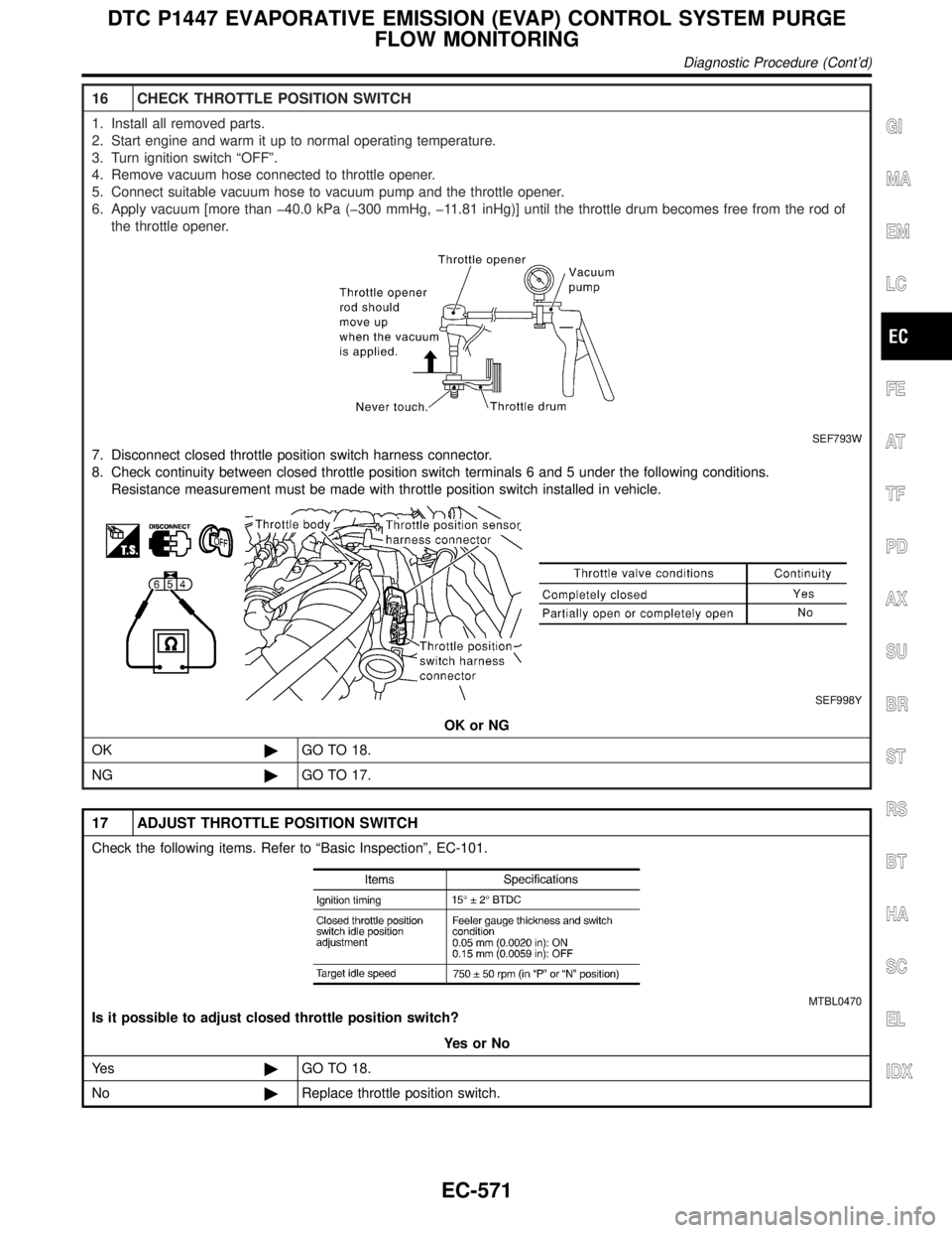
16 CHECK THROTTLE POSITION SWITCH
1. Install all removed parts.
2. Start engine and warm it up to normal operating temperature.
3. Turn ignition switch ªOFFº.
4. Remove vacuum hose connected to throttle opener.
5. Connect suitable vacuum hose to vacuum pump and the throttle opener.
6. Apply vacuum [more than þ40.0 kPa (þ300 mmHg, þ11.81 inHg)] until the throttle drum becomes free from the rod of
the throttle opener.
SEF793W
7. Disconnect closed throttle position switch harness connector.
8. Check continuity between closed throttle position switch terminals 6 and 5 under the following conditions.
Resistance measurement must be made with throttle position switch installed in vehicle.
SEF998Y
OK or NG
OK©GO TO 18.
NG©GO TO 17.
17 ADJUST THROTTLE POSITION SWITCH
Check the following items. Refer to ªBasic Inspectionº, EC-101.
MTBL0470
Is it possible to adjust closed throttle position switch?
YesorNo
Ye s©GO TO 18.
No©Replace throttle position switch.
GI
MA
EM
LC
FE
AT
TF
PD
AX
SU
BR
ST
RS
BT
HA
SC
EL
IDX
DTC P1447 EVAPORATIVE EMISSION (EVAP) CONTROL SYSTEM PURGE
FLOW MONITORING
Diagnostic Procedure (Cont'd)
EC-571
Page 1109 of 2395

Possible CauseNBEC0591IEVAP canister vent control valve
IEVAP control system pressure sensor and circuit
IBlocked rubber tube to EVAP canister vent control valve
IWater separator
IEVAP canister is saturated with water.
IVacuum cut valve
DTC Confirmation ProcedureNBEC0342NOTE:
IIf DTC P1448 is displayed with P0440 or P1440, perform
trouble diagnosis for DTC P1448 first.
IIf ªDTC Confirmation Procedureº has been previously
conducted, always turn ignition switch ªOFFº and wait at least
10 seconds before conducting the next test.
SEF565X
SEF566X
SEF567X
WITH CONSULT-IINBEC0342S01TESTING CONDITION:
IPerform ªDTC WORK SUPPORTº when the fuel level is
between 1/4 to 3/4 full and vehicle is placed on flat level
surface.
IOpen engine hood before conducting the following proce-
dure.
1) Turn ignition switch ªONº.
2) Turn ignition switch ªOFFº and wait at least 10 seconds.
3) Turn ignition switch ªONº and select ªDATA MONITORº mode
with CONSULT-II.
4) Make sure that the following conditions are met.
COOLAN TEMP/S 0 - 70ÉC (32 - 158ÉF)
INT/A TEMP SE 0 - 30ÉC (32 - 86ÉF)
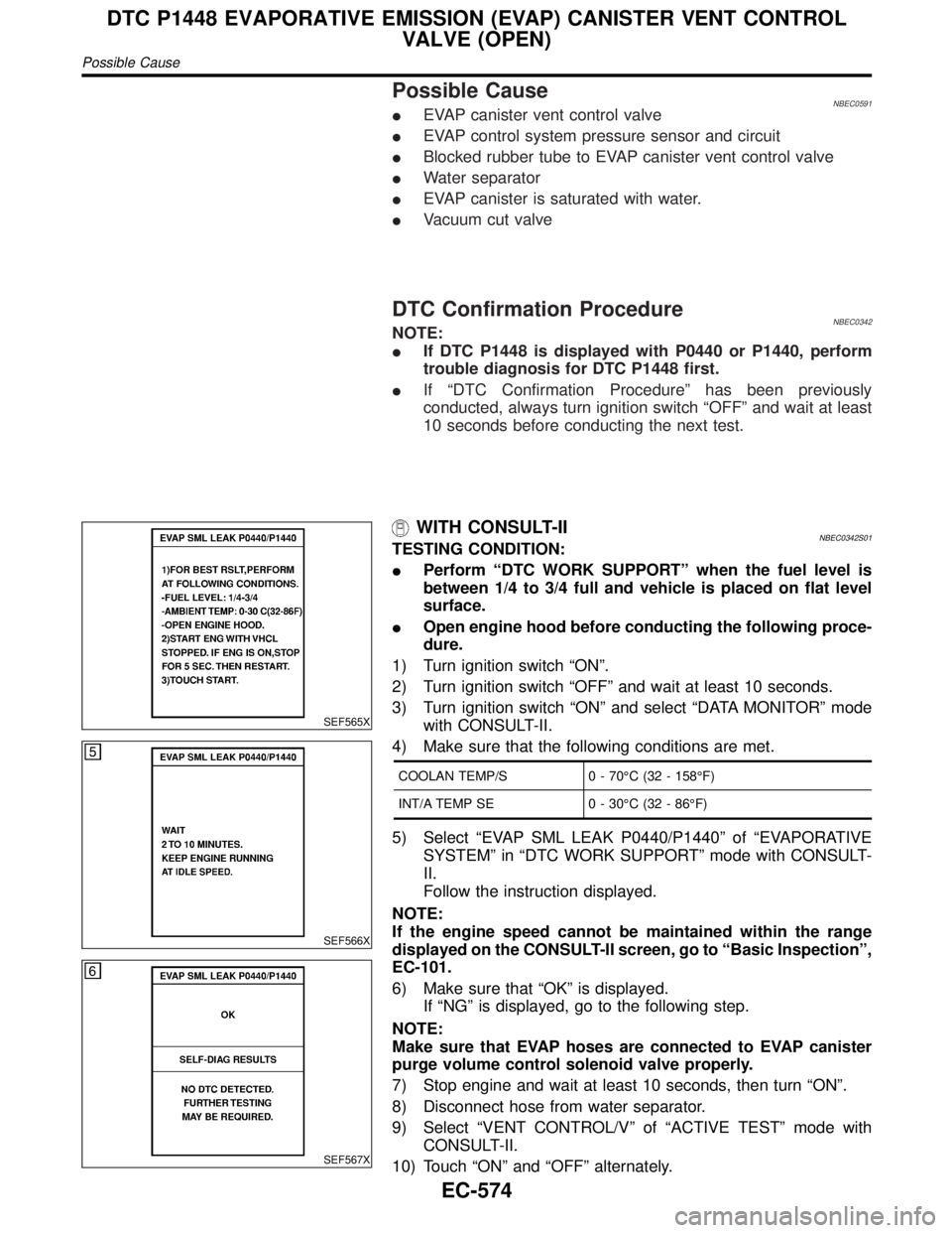
5) Select ªEVAP SML LEAK P0440/P1440º of ªEVAPORATIVE
SYSTEMº in ªDTC WORK SUPPORTº mode with CONSULT-
II.
Follow the instruction displayed.
NOTE:
If the engine speed cannot be maintained within the range
displayed on the CONSULT-II screen, go to ªBasic Inspectionº,
EC-101.
6) Make sure that ªOKº is displayed.
If ªNGº is displayed, go to the following step.
NOTE:
Make sure that EVAP hoses are connected to EVAP canister
purge volume control solenoid valve properly.
7) Stop engine and wait at least 10 seconds, then turn ªONº.
8) Disconnect hose from water separator.
9) Select ªVENT CONTROL/Vº of ªACTIVE TESTº mode with
CONSULT-II.
10) Touch ªONº and ªOFFº alternately.
DTC P1448 EVAPORATIVE EMISSION (EVAP) CANISTER VENT CONTROL
VALVE (OPEN)
Possible Cause
EC-574
Page 1121 of 2395
On Board Diagnosis LogicNBEC0349Malfunction is detected when an improper voltage signal is sent to
ECM through vacuum cut valve bypass valve.
Possible CauseNBEC0592IHarness or connectors
(The vacuum cut valve bypass valve circuit is open or shorted.)
IVacuum cut valve bypass valve
DTC Confirmation ProcedureNBEC0350NOTE:
If ªDTC Confirmation Procedureº has been previously conducted,
always turn ignition switch ªOFFº and wait at least 10 seconds
before conducting the next test.
TESTING CONDITION:
Before performing the following procedure, confirm that bat-
tery voltage is more than 11V at idle speed.
SEF058Y
WITH CONSULT-IINBEC0350S011) Turn ignition switch ªONº.
2) Select ªDATA MONITORº mode with CONSULT-II.
3) Start engine and wait at least 5 seconds.
4) If 1st trip DTC is detected, go to ªDiagnostic Procedureº,
EC-588.
WITH GSTNBEC0350S02Follow the procedure ªWITH CONSULT-IIº above.
DTC P1490 VACUUM CUT VALVE BYPASS VALVE (CIRCUIT)
On Board Diagnosis Logic
EC-586