Page 1031 of 2395
Diagnostic ProcedureNBEC0539
1 CHECK HOSES
1. Turn ignition switch ªOFFº.
2. Check hose for clogging or improper connection.
SEF109L
OK or NG
OK©GO TO 2.
NG©Repair or reconnect the hose.
2 CHECK SWIRL CONTROL VALVE CONTROL VACUUM CHECK SWITCH GROUND CIRCUIT FOR OPEN
AND SHORT
1. Disconnect swirl control valve control vacuum check switch harness connector.
SEF999Y
2. Check harness continuity between terminal 2 and ground. Refer to Wiring Diagram.
Continuity should exist.
3. Also check harness for short to power.
OK or NG
OK©GO TO 4.
NG©GO TO 3.
3 DETECT MALFUNCTIONING PART
Check the following.
IHarness connectors E1, M1 and M92, F27
IHarness for open between swirl control valve control vacuum check switch and engine ground
©Repair open circuit or short to power in harness connectors.
DTC P1165 SWIRL CONTROL VALVE CONTROL VACUUM CHECK SWITCH
Diagnostic Procedure
EC-496
Page 1033 of 2395

6 CHECK SWIRL CONTROL VALVE CONTROL SOLENOID VALVE
With CONSULT-II
1. Reconnect the disconnected harness connectors.
2. Start engine and let it idle.
3. Remove vacuum hose connected to swirl control valve actuator.
4. Select ªSWIRL CONT SOL/Vº in ªACTIVE TESTº mode with CONSULT-II.
5. Touch ªONº and ªOFFº on CONSULT-II screen.
6. Check vacuum existence and operation delay time under the following conditions.
SEF004Z
Without CONSULT-II
1. Reconnect ECM harness connector.
2. Remove vacuum hose connected to swirl control valve actuator.
3. Start engine and let it idle.
4. Apply 12V of direct current between swirl control valve control solenoid valve terminals and 2.
5. Check vacuum existence and operation delay time under the following conditions.
SEF005Z
OK or NG
OK©GO TO 7.
NG©Replace intake manifold collector assembly.
7 CHECK INTERMITTENT INCIDENT
Perform ªTROUBLE DIAGNOSIS FOR INTERMITTENT INCIDENTº, EC-140.
©INSPECTION END
DTC P1165 SWIRL CONTROL VALVE CONTROL VACUUM CHECK SWITCH
Diagnostic Procedure (Cont'd)
EC-498
Page 1034 of 2395

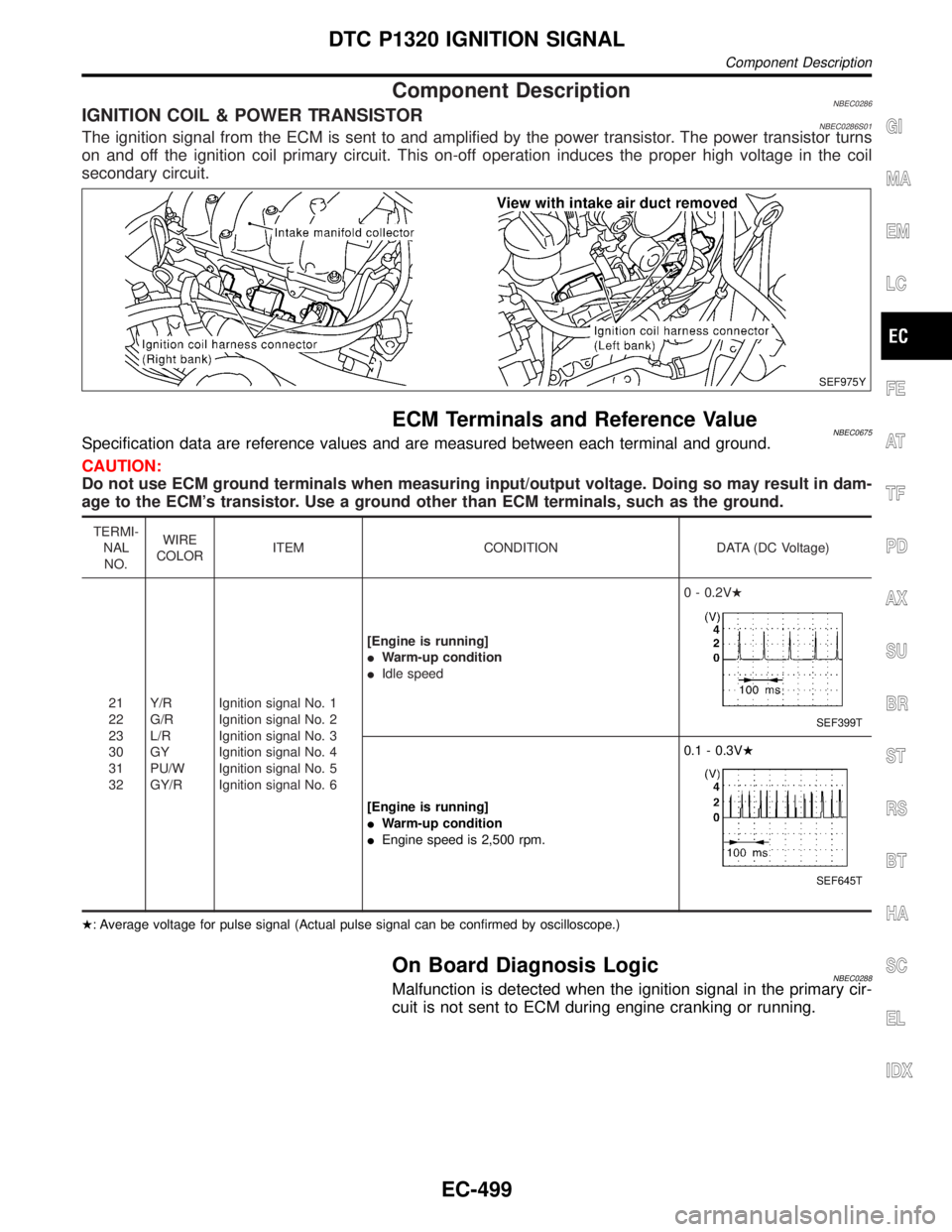
Component DescriptionNBEC0286IGNITION COIL & POWER TRANSISTORNBEC0286S01The ignition signal from the ECM is sent to and amplified by the power transistor. The power transistor turns
on and off the ignition coil primary circuit. This on-off operation induces the proper high voltage in the coil
secondary circuit.
SEF975Y
ECM Terminals and Reference ValueNBEC0675Specification data are reference values and are measured between each terminal and ground.
CAUTION:
Do not use ECM ground terminals when measuring input/output voltage. Doing so may result in dam-
age to the ECM's transistor. Use a ground other than ECM terminals, such as the ground.
TERMI-
NAL
NO.WIRE
COLORITEM CONDITION DATA (DC Voltage)
21
22
23
30
31
32Y/R
G/R
L/R
GY
PU/W
GY/RIgnition signal No. 1
Ignition signal No. 2
Ignition signal No. 3
Ignition signal No. 4
Ignition signal No. 5
Ignition signal No. 6[Engine is running]
IWarm-up condition
IIdle speed0 - 0.2VH
SEF399T
[Engine is running]
IWarm-up condition
IEngine speed is 2,500 rpm.0.1 - 0.3VH
SEF645T
H: Average voltage for pulse signal (Actual pulse signal can be confirmed by oscilloscope.)
On Board Diagnosis LogicNBEC0288Malfunction is detected when the ignition signal in the primary cir-
cuit is not sent to ECM during engine cranking or running.
GI
MA
EM
LC
FE
AT
TF
PD
AX
SU
BR
ST
RS
BT
HA
SC
EL
IDX
DTC P1320 IGNITION SIGNAL
Component Description
EC-499
Page 1035 of 2395

Possible CauseNBEC0572IHarness or connectors (The ignition primary circuit is open or
shorted.)
IPower transistor unit built into ignition coil
ICondenser
ICrankshaft position sensor (REF)
ICrankshaft position sensor (REF) circuit
SEF058Y
DTC Confirmation ProcedureNBEC0289NOTE:
IIf ªDTC Confirmation Procedureº has been previously
conducted, always turn ignition switch ªOFFº and wait at least
10 seconds before conducting the next test.
IIf DTC P1320 is displayed with DTC P0335, P0340, P1335
or P1336, perform trouble diagnosis for DTC P0335,
P0340, P1335 or P1336 first. Refer to EC-334, EC-342,
EC-510 or EC-517.
WITH CONSULT-IINBEC0289S011) Turn ignition switch ªONº.
2) Select ªDATA MONITORº mode with CONSULT-II.
3) Start engine. (If engine does not run, turn ignition switch to
ªSTARTº for at least 5 seconds.)
4) If 1st trip DTC is detected, go to ªDiagnostic Procedureº,
EC-504.
WITH GSTNBEC0289S02Follow the procedure ªWITH CONSULT-IIº above.
DTC P1320 IGNITION SIGNAL
Possible Cause
EC-500
Page 1039 of 2395
Diagnostic ProcedureNBEC0291
1 CHECK ENGINE START
Turn ignition switch ªOFFº, and restart engine.
Is engine running?
YesorNo
Yes (With CONSULT-II)©GO TO 2.
Yes (Without CONSULT-
II)©GO TO 12.
No©GO TO 3.
2 SEARCH FOR MALFUNCTIONING CIRCUIT
With CONSULT-II
1. Perform ªPOWER BALANCEº in ªACTIVE TESTº mode with CONSULT-II.
2. Search for circuit which does not produce a momentary engine speed drop.
SEF190Y
©GO TO 12.
3 CHECK IGNITION COIL POWER SUPPLY CIRCUIT-I
1. Turn ignition switch ON.
2. Check voltage between ECM terminals 110, 112 and ground with CONSULT-II or tester.
SEF366X
OK or NG
OK©GO TO 4.
NG©Go to TROUBLE DIAGNOSIS FOR POWER SUPPLY, EC-142.
DTC P1320 IGNITION SIGNAL
Diagnostic Procedure
EC-504
Page 1042 of 2395
10 CHECK CONDENSER GROUND CIRCUIT FOR OPEN AND SHORT
1. Turn ignition switch OFF.
2. Check harness continuity between condenser terminal 2 and engine ground. Refer to Wiring Diagram.
Continuity should exist.
3. Also check harness for short to power.
OK or NG
OK©GO TO 11.
NG©Repair open circuit or short to power in harness or connectors.
11 CHECK CONDENSER
Check resistance between condenser terminals 1 and 2.
SEF369X
OK or NG
OK©GO TO 12.
NG©Replace condenser.
GI
MA
EM
LC
FE
AT
TF
PD
AX
SU
BR
ST
RS
BT
HA
SC
EL
IDX
DTC P1320 IGNITION SIGNAL
Diagnostic Procedure (Cont'd)
EC-507
Page 1043 of 2395
12 CHECK IGNITION COIL POWER SUPPLY CIRCUIT-V
1. Turn ignition switch OFF.
2. Reconnect harness connectors disconnected.
3. Disconnect ignition coil harness connector.
SEF975Y
4. Turn ignition switch ON.
5. Check voltage between ignition coil terminal 3 and ground with CONSULT-II or tester.
SEF370X
OK or NG
OK©GO TO 14.
NG©GO TO 13.
13 DETECT MALFUNCTIONING PART
Check the harness for open or short between ignition coil and harness connector F22.
©Repair or replace harness or connectors.
14 CHECK IGNITION COIL GROUND CIRCUIT FOR OPEN AND SHORT
1. Turn ignition switch OFF.
2. Check harness continuity between ignition coil terminal 2 and engine ground. Refer to Wiring Diagram.
Continuity should exist.
3. Also check harness for short to power.
OK or NG
OK©GO TO 15.
NG©Repair open circuit or short to power in harness or connectors.
DTC P1320 IGNITION SIGNAL
Diagnostic Procedure (Cont'd)
EC-508
Page 1045 of 2395

SEF253P
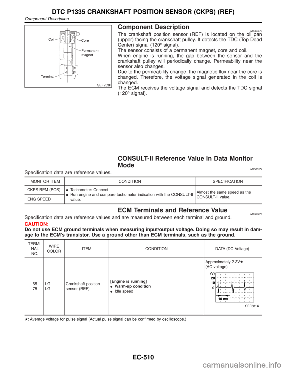
Component DescriptionNBEC0573The crankshaft position sensor (REF) is located on the oil pan
(upper) facing the crankshaft pulley. It detects the TDC (Top Dead
Center) signal (120É signal).
The sensor consists of a permanent magnet, core and coil.
When engine is running, the gap between the sensor and the
crankshaft pulley will periodically change. Permeability near the
sensor also changes.
Due to the permeability change, the magnetic flux near the core is
changed. Therefore, the voltage signal generated in the coil is
changed.
The ECM receives the voltage signal and detects the TDC signal
(120É signal).
CONSULT-II Reference Value in Data Monitor
Mode
NBEC0574Specification data are reference values.
MONITOR ITEM CONDITION SPECIFICATION
CKPS´RPM (POS)ITachometer: Connect
IRun engine and compare tachometer indication with the CONSULT-II
value.Almost the same speed as the
CONSULT-II value.
ENG SPEED
ECM Terminals and Reference ValueNBEC0676Specification data are reference values and are measured between each terminal and ground.
CAUTION:
Do not use ECM ground terminals when measuring input/output voltage. Doing so may result in dam-
age to the ECM's transistor. Use a ground other than ECM terminals, such as the ground.
TERMI-
NAL
NO.WIRE
COLORITEM CONDITION DATA (DC Voltage)
65
75LG
LGCrankshaft position
sensor (REF)[Engine is running]
IWarm-up condition
IIdle speedApproximately 2.3VH
(AC voltage)
SEF581X
H: Average voltage for pulse signal (Actual pulse signal can be confirmed by oscilloscope.)
DTC P1335 CRANKSHAFT POSITION SENSOR (CKPS) (REF)
Component Description
EC-510