2001 INFINITI QX4 engine
[x] Cancel search: enginePage 1185 of 2395
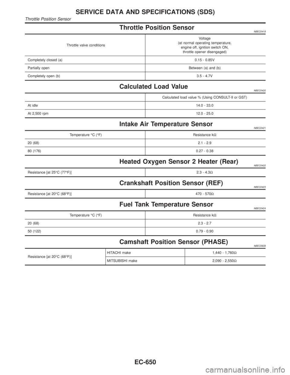
Throttle Position SensorNBEC0419
Throttle valve conditionsVoltage
(at normal operating temperature,
engine off, ignition switch ON,
throttle opener disengaged)
Completely closed (a)0.15 - 0.85V
Partially openBetween (a) and (b)
Completely open (b)3.5 - 4.7V
Calculated Load ValueNBEC0420
Calculated load value % (Using CONSULT-II or GST)
At idle14.0 - 33.0
At 2,500 rpm12.0 - 25.0
Intake Air Temperature SensorNBEC0421
Temperature ÉC (ÉF) Resistance kW
20 (68)2.1 - 2.9
80 (176)0.27 - 0.38
Heated Oxygen Sensor 2 Heater (Rear)NBEC0422
Resistance [at 25ÉC (77ÉF)]2.3 - 4.3W
Crankshaft Position Sensor (REF)NBEC0423
Resistance [at 20ÉC (68ÉF)]470 - 570W
Fuel Tank Temperature SensorNBEC0424
Temperature ÉC (ÉF) Resistance kW
20 (68)2.3 - 2.7
50 (122)0.79 - 0.90
Camshaft Position Sensor (PHASE)NBEC0639
Resistance [at 20ÉC (68ÉF)]HITACHI make 1,440 - 1,760W
MITSUBISHI make 2,090 - 2,550W
SERVICE DATA AND SPECIFICATIONS (SDS)
Throttle Position Sensor
EC-650
Page 1188 of 2395
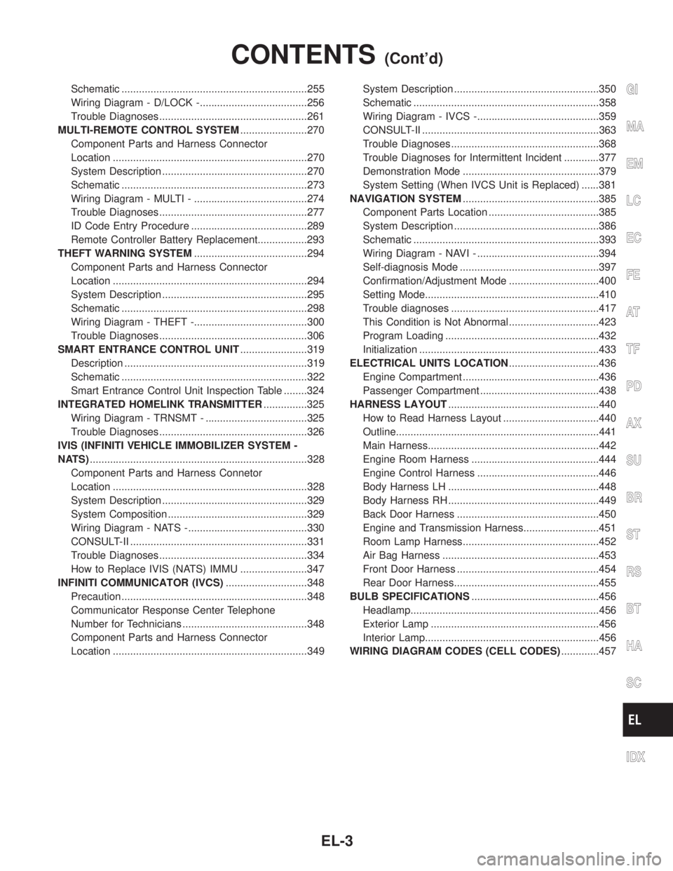
Schematic ................................................................255
Wiring Diagram - D/LOCK -.....................................256
Trouble Diagnoses...................................................261
MULTI-REMOTE CONTROL SYSTEM.......................270
Component Parts and Harness Connector
Location ...................................................................270
System Description ..................................................270
Schematic ................................................................273
Wiring Diagram - MULTI - .......................................274
Trouble Diagnoses...................................................277
ID Code Entry Procedure ........................................289
Remote Controller Battery Replacement.................293
THEFT WARNING SYSTEM.......................................294
Component Parts and Harness Connector
Location ...................................................................294
System Description ..................................................295
Schematic ................................................................298
Wiring Diagram - THEFT -.......................................300
Trouble Diagnoses...................................................306
SMART ENTRANCE CONTROL UNIT.......................319
Description ...............................................................319
Schematic ................................................................322
Smart Entrance Control Unit Inspection Table ........324
INTEGRATED HOMELINK TRANSMITTER...............325
Wiring Diagram - TRNSMT - ...................................325
Trouble Diagnoses...................................................326
IVIS (INFINITI VEHICLE IMMOBILIZER SYSTEM -
NATS)...........................................................................328
Component Parts and Harness Connetor
Location ...................................................................328
System Description ..................................................329
System Composition ................................................329
Wiring Diagram - NATS -.........................................330
CONSULT-II .............................................................331
Trouble Diagnoses...................................................334
How to Replace IVIS (NATS) IMMU .......................347
INFINITI COMMUNICATOR (IVCS)............................348
Precaution ................................................................348
Communicator Response Center Telephone
Number for Technicians ...........................................348
Component Parts and Harness Connector
Location ...................................................................349System Description ..................................................350
Schematic ................................................................358
Wiring Diagram - IVCS -..........................................359
CONSULT-II .............................................................363
Trouble Diagnoses...................................................368
Trouble Diagnoses for Intermittent Incident ............377
Demonstration Mode ...............................................379
System Setting (When IVCS Unit is Replaced) ......381
NAVIGATION SYSTEM...............................................385
Component Parts Location ......................................385
System Description ..................................................386
Schematic ................................................................393
Wiring Diagram - NAVI - ..........................................394
Self-diagnosis Mode ................................................397
Confirmation/Adjustment Mode ...............................400
Setting Mode............................................................410
Trouble diagnoses ...................................................417
This Condition is Not Abnormal ...............................423
Program Loading .....................................................432
Initialization ..............................................................433
ELECTRICAL UNITS LOCATION...............................436
Engine Compartment ...............................................436
Passenger Compartment .........................................438
HARNESS LAYOUT....................................................440
How to Read Harness Layout .................................440
Outline......................................................................441
Main Harness...........................................................442
Engine Room Harness ............................................444
Engine Control Harness ..........................................446
Body Harness LH ....................................................448
Body Harness RH ....................................................449
Back Door Harness .................................................450
Engine and Transmission Harness..........................451
Room Lamp Harness...............................................452
Air Bag Harness ......................................................453
Front Door Harness .................................................454
Rear Door Harness..................................................455
BULB SPECIFICATIONS............................................456
Headlamp.................................................................456
Exterior Lamp ..........................................................456
Interior Lamp............................................................456
WIRING DIAGRAM CODES (CELL CODES).............457GI
MA
EM
LC
EC
FE
AT
TF
PD
AX
SU
BR
ST
RS
BT
HA
SC
IDX
CONTENTS(Cont'd)
EL-3
Page 1205 of 2395

ENGINE ROOM HARNESSNBEL0008S02
MEL418N
GROUND
Ground Distribution (Cont'd)
EL-20
Page 1207 of 2395

ENGINE CONTROL HARNESSNBEL0008S03
MEL147M
GROUND
Ground Distribution (Cont'd)
EL-22
Page 1231 of 2395

Component Parts and Harness Connector
Location
NBEL0161
SEL460X
System DescriptionNBEL0192The headlamp system for Canada vehicles contains a daytime light control unit that activates the high beam
headlamps at approximately half illumination whenever the engine is running. If the parking brake is applied
before the engine is started the daytime lights will not be illuminated. The daytime lights will illuminate once
the parking brake is released. Thereafter, the daytime lights will continue to operate when the parking brake
is applied.
And battery saver system is controlled by the headlamp battery saver control unit and smart entrance control
unit.
Power is supplied at all times
Ito headlamp LH relay terminals 1 and 3
Ithrough 15A fuse (No. 60, located in the fuse and fusible link box), and
Ito headlamp LH relay terminal 6
Ithrough 20A fuse (No. 32, located in the fuse and fusible link box), and
Ito headlamp RH relay terminals 1 and 3
Ithrough 15A fuse (No. 59, located in the fuse and fusible link box), and
Ito headlamp RH relay terminal 6
Ithrough 20A fuse (No. 31, located in the fuse and fusible link box), and
Ito headlamp battery saver control unit terminal 7, and
Ito smart entrance control unit terminal 10
Ithrough 7.5A fuse [No. 24, located in the fuse block (J/B)].
Ground is supplied
Ito daytime light control unit terminal 16,
Ito auto light control unit terminal 5 and
Ito headlamp battery saver control unit terminals 4 and 11.
When the ignition switch is in the ON or START position, power is also supplied
HEADLAMP (FOR CANADA) Ð DAYTIME LIGHT SYSTEM Ð
Component Parts and Harness Connector Location
EL-46
Page 1233 of 2395
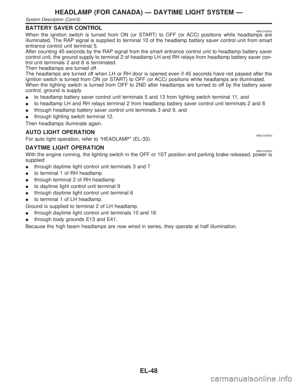
BATTERY SAVER CONTROLNBEL0192S02When the ignition switch is turned from ON (or START) to OFF (or ACC) positions while headlamps are
illuminated, The RAP signal is supplied to terminal 10 of the headlamp battery saver control unit from smart
entrance control unit terminal 5.
After counting 45 seconds by the RAP signal from the smart entrance control unit to headlamp battery saver
control unit, the ground supply to terminal 2 of headlamp LH and RH relays from headlamp battery saver con-
trol unit terminals 2 and 8 is terminated.
Then headlamps are turned off.
The headlamps are turned off when LH or RH door is opened even if 45 seconds have not passed after the
ignition switch is turned from ON (or START) to OFF (or ACC) positions while headlamps are illuminated.
When the lighting switch is turned from OFF to 2ND after headlamps are turned to off by the battery saver
control, ground is supply
Ito headlamp battery saver control unit terminals 5 and 13 from lighting switch terminal 11, and
Ito headlamp LH and RH relays terminal 2 from headlamp battery saver control unit terminals 2 and 8
Ithrough headlamp battery saver control unit terminals 3 and 9, and
Ithrough lighting switch terminal 12.
Then headlamps illuminate again.
AUTO LIGHT OPERATIONNBEL0192S03For auto light operation, refer to ªHEADLAMPº (EL-33).
DAYTIME LIGHT OPERATIONNBEL0192S04With the engine running, the lighting switch in the OFF or 1ST position and parking brake released, power is
supplied
Ithrough daytime light control unit terminals 3 and 7
Ito terminal 1 of RH headlamp
Ithrough terminal 2 of RH headlamp
Ito daytime light control unit terminal 9
Ithrough daytime light control unit terminal 6
Ito terminal 1 of LH headlamp.
Ground is supplied to terminal 2 of LH headlamp.
Ithrough daytime light control unit terminals 10 and 16
Ithrough body grounds E13 and E41.
Because the high beam headlamps are now wired in series, they operate at half illumination.
HEADLAMP (FOR CANADA) Ð DAYTIME LIGHT SYSTEM Ð
System Description (Cont'd)
EL-48
Page 1234 of 2395
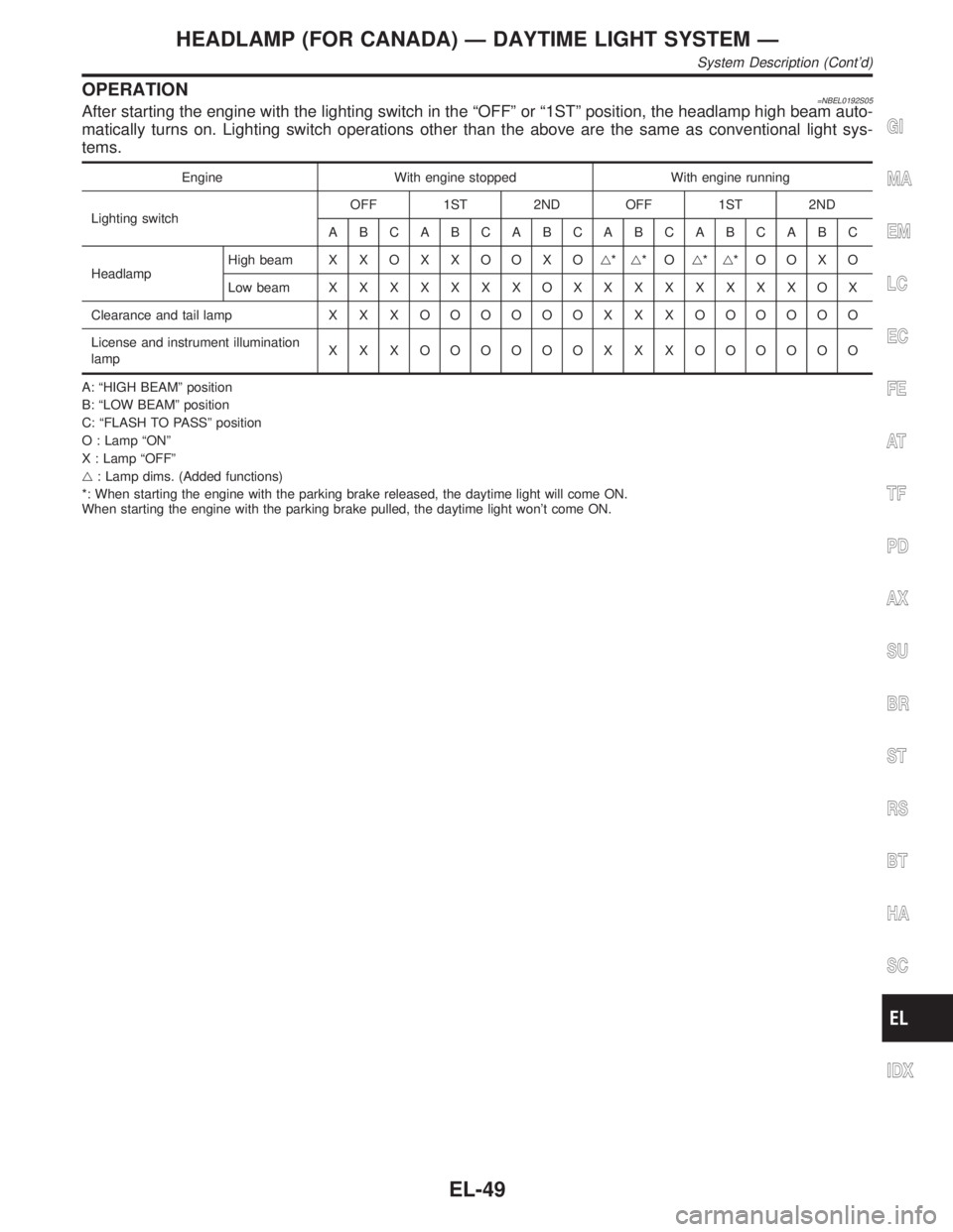
OPERATION=NBEL0192S05After starting the engine with the lighting switch in the ªOFFº or ª1STº position, the headlamp high beam auto-
matically turns on. Lighting switch operations other than the above are the same as conventional light sys-
tems.
Engine With engine stopped With engine running
Lighting switchOFF 1ST 2ND OFF 1ST 2ND
ABCABCABCABCABCABC
HeadlampHigh beam X X O X X O O X Og*g*Og*g*OOXO
Low beamXXXXXXXOXXXXXXXXOX
Clearance and tail lamp X X XOOOOOO X X X OOOOOO
License and instrument illumination
lampX X X OOOOOO X X X OOOOOO
A: ªHIGH BEAMº position
B: ªLOW BEAMº position
C: ªFLASH TO PASSº position
O : Lamp ªONº
X : Lamp ªOFFº
g: Lamp dims. (Added functions)
*: When starting the engine with the parking brake released, the daytime light will come ON.
When starting the engine with the parking brake pulled, the daytime light won't come ON.
GI
MA
EM
LC
EC
FE
AT
TF
PD
AX
SU
BR
ST
RS
BT
HA
SC
IDX
HEADLAMP (FOR CANADA) Ð DAYTIME LIGHT SYSTEM Ð
System Description (Cont'd)
EL-49
Page 1241 of 2395
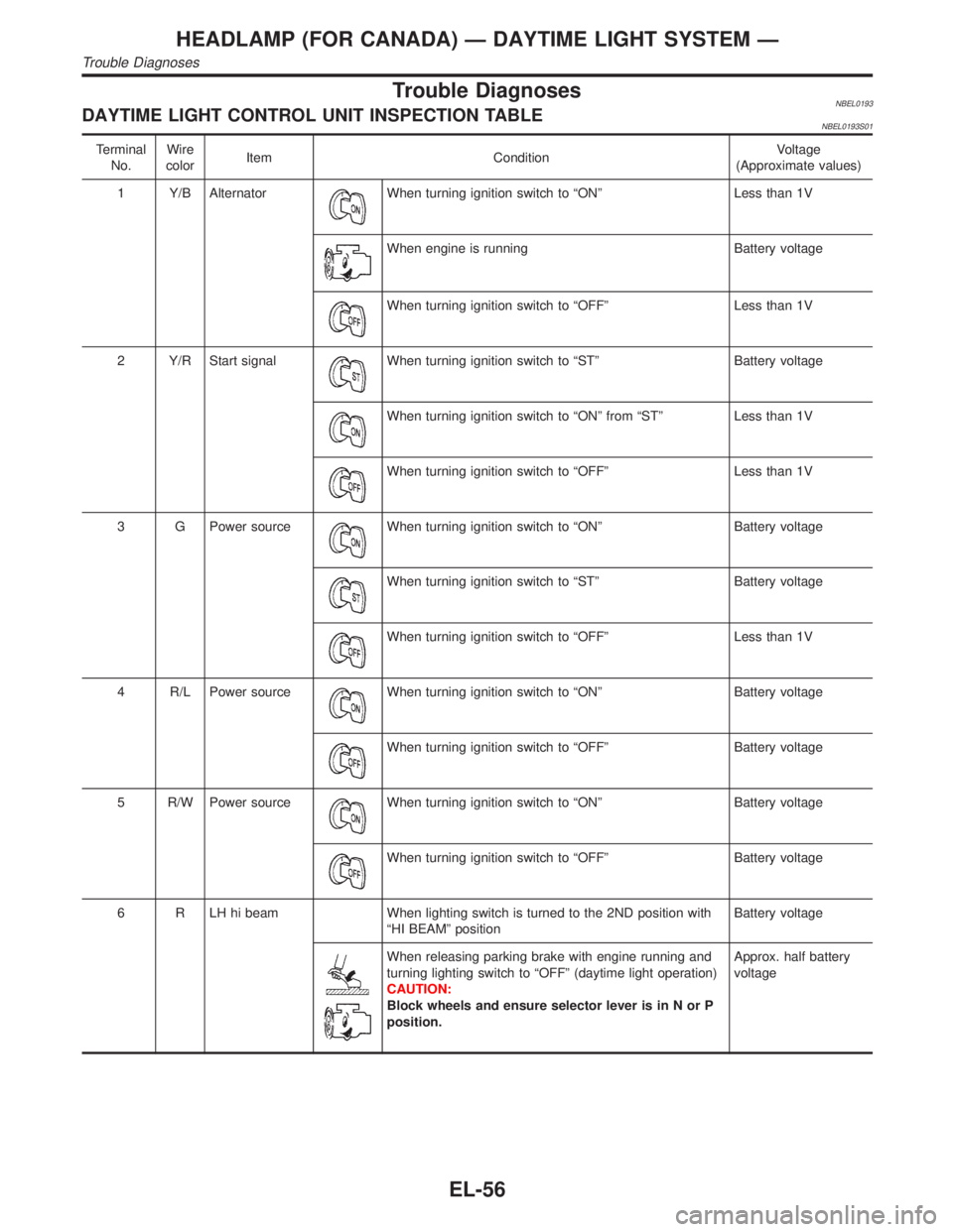
Trouble DiagnosesNBEL0193DAYTIME LIGHT CONTROL UNIT INSPECTION TABLENBEL0193S01
Terminal
No.Wire
colorItem ConditionVoltage
(Approximate values)
1 Y/B Alternator
When turning ignition switch to ªONº Less than 1V
When engine is running Battery voltage
When turning ignition switch to ªOFFº Less than 1V
2 Y/R Start signal
When turning ignition switch to ªSTº Battery voltage
When turning ignition switch to ªONº from ªSTº Less than 1V
When turning ignition switch to ªOFFº Less than 1V
3 G Power source
When turning ignition switch to ªONº Battery voltage
When turning ignition switch to ªSTº Battery voltage
When turning ignition switch to ªOFFº Less than 1V
4 R/L Power source
When turning ignition switch to ªONº Battery voltage
When turning ignition switch to ªOFFº Battery voltage
5 R/W Power source
When turning ignition switch to ªONº Battery voltage
When turning ignition switch to ªOFFº Battery voltage
6 R LH hi beam When lighting switch is turned to the 2ND position with
ªHI BEAMº positionBattery voltage
When releasing parking brake with engine running and
turning lighting switch to ªOFFº (daytime light operation)
CAUTION:
Block wheels and ensure selector lever is in N or P
position.Approx. half battery
voltage
HEADLAMP (FOR CANADA) Ð DAYTIME LIGHT SYSTEM Ð
Trouble Diagnoses
EL-56