2001 INFINITI QX4 change time
[x] Cancel search: change timePage 1097 of 2395
IEVAP canister vent control valve
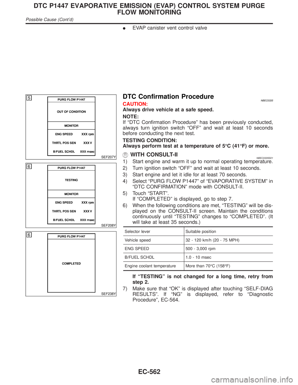
SEF207Y
SEF208Y
SEF238Y
DTC Confirmation ProcedureNBEC0335CAUTION:
Always drive vehicle at a safe speed.
NOTE:
If ªDTC Confirmation Procedureº has been previously conducted,
always turn ignition switch ªOFFº and wait at least 10 seconds
before conducting the next test.
TESTING CONDITION:
Always perform test at a temperature of 5ÉC (41ÉF) or more.
WITH CONSULT-IINBEC0335S011) Start engine and warm it up to normal operating temperature.
2) Turn ignition switch ªOFFº and wait at least 10 seconds.
3) Start engine and let it idle for at least 70 seconds.
4) Select ªPURG FLOW P1447º of ªEVAPORATIVE SYSTEMº in
ªDTC CONFIRMATIONº mode with CONSULT-II.
5) Touch ªSTARTº.
If ªCOMPLETEDº is displayed, go to step 7.
6) When the following conditions are met, ªTESTINGº will be dis-
played on the CONSULT-II screen. Maintain the conditions
continuously until ªTESTINGº changes to ªCOMPLETEDº. (It
will take at least 35 seconds.)
Selector lever Suitable position
Vehicle speed 32 - 120 km/h (20 - 75 MPH)
ENG SPEED 500 - 3,000 rpm
B/FUEL SCHDL 1.0 - 10 msec
Engine coolant temperature More than 70ÉC (158ÉF)
If ªTESTINGº is not changed for a long time, retry from
step 2.
7) Make sure that ªOKº is displayed after touching ªSELF-DIAG
RESULTSº. If ªNGº is displayed, refer to ªDiagnostic
Procedureº, EC-564.
DTC P1447 EVAPORATIVE EMISSION (EVAP) CONTROL SYSTEM PURGE
FLOW MONITORING
Possible Cause (Cont'd)
EC-562
Page 1218 of 2395

Ito headlamp battery saver control unit terminals 5 and 13 from lighting switch terminal 11, and
Ito headlamp LH and RH relays terminal 2 from headlamp battery saver control unit terminals 2 and 8
Ithrough headlamp battery saver control unit terminals 3 and 9, and
Ithrough lighting switch terminal 12.
Then headlamps illuminate again.
AUTO LIGHT OPERATIONNBEL0188S05When lighting switch is in ªAUTOº position, ground is supplied
Ito auto light control unit terminal 10
Ifrom lighting switch terminal 42.
When ignition switch is turn to ªONº or ªSTARTº position and outside brightness is darker than prescribed level.
Ground is supplied
Ito headlamp relay LH and RH terminals 2
Ithrough battery saver control unit
Ifrom auto light control unit terminal 6, and
Ito tail lamp relay terminal 1
Ithrough battery saver control unit
Ifrom auto light control unit terminal 7.
Then both headlamp relays and tail lamp relay are energized, headlamps (low or high) and tail lamps are illu-
minate according to switch position.
Auto light operation allows headlamps and tail lamps to go off when
IIgnition switch is turned to ªOFFº position or
IOutside brightness is brighter than prescribed level.
NOTE:
The delay time is varies up to maximum of 20 seconds as the outside brightness changes.
For parking, license and tail lamp auto operation, refer to ªPARKING, LICENSE AND TAIL LAMPSº.
THEFT WARNING SYSTEMNBEL0188S06The theft warning system will flash the low beams if the system is triggered. Refer to ªTHEFT WARNING
SYSTEMº (EL-296).
GI
MA
EM
LC
EC
FE
AT
TF
PD
AX
SU
BR
ST
RS
BT
HA
SC
IDX
HEADLAMP (FOR USA) Ð XENON TYPE Ð
System Description (Cont'd)
EL-33
Page 1285 of 2395
Meter/Gauge Operation and Odo/Trip Meter
Segment Check in Diagnosis Mode
NBEL0200DIAGNOSIS FUNCTIONNBEL0200S01IOdo/trip meter segment can be checked in diagnosis mode.
IMeters/gauges can be checked in diagnosis mode.
HOW TO ALTERNATE DIAGNOSIS MODENBEL0200S021. Turn ignition switch to ON and change odo/trip meter to ªTRIP
Aº or ªTRIP Bº.
2. Turn ignition switch to OFF.
3. Turn ignition switch to ON when pushing odo/trip meter switch.
4. Push odo/trip meter switch 1 second.
5. Release odo/trip meter switch.
6. Push odo/trip meter switch more than three times within 7
seconds.
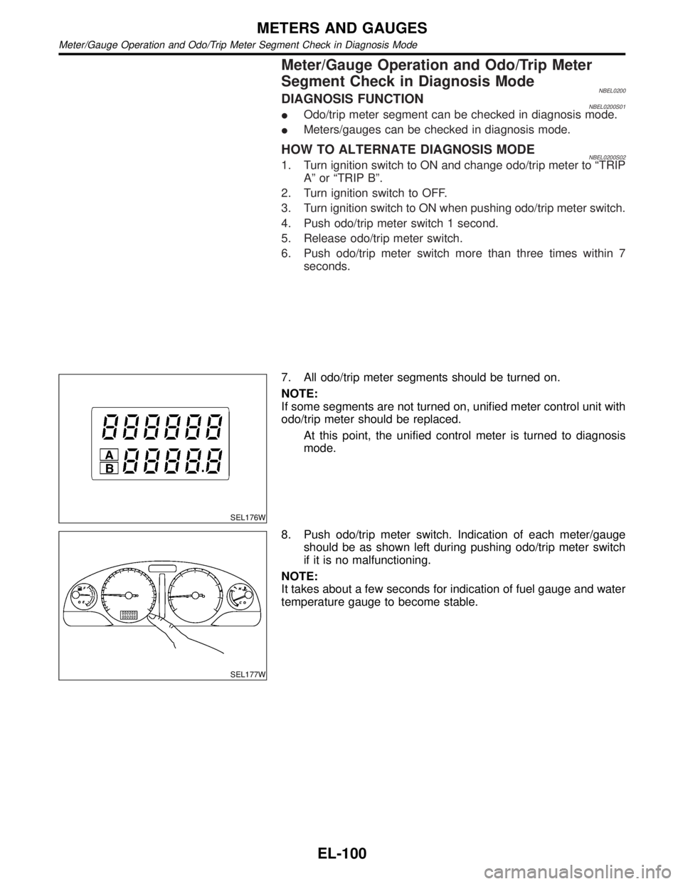
SEL176W
7. All odo/trip meter segments should be turned on.
NOTE:
If some segments are not turned on, unified meter control unit with
odo/trip meter should be replaced.
At this point, the unified control meter is turned to diagnosis
mode.
SEL177W
8. Push odo/trip meter switch. Indication of each meter/gauge
should be as shown left during pushing odo/trip meter switch
if it is no malfunctioning.
NOTE:
It takes about a few seconds for indication of fuel gauge and water
temperature gauge to become stable.
METERS AND GAUGES
Meter/Gauge Operation and Odo/Trip Meter Segment Check in Diagnosis Mode
EL-100
Page 1456 of 2395
When the front door switch LH is OPEN, ground is supplied
Ito smart entrance control unit terminal 29
Ithrough front door switch LH terminal 1
Ito front door switch LH terminal 2
Ithrough body grounds B11, B22 and D210.
When the front door switch RH is OPEN, ground is supplied
Ito smart entrance control unit terminal 40
Ithrough front door switch RH body ground.
When the other door switches are OPEN, ground is supplied
Ito smart entrance control unit terminal 28
Ithrough other door switches body grounds.
Remote controller signal is inputted to smart entrance control unit (The antenna of the system is combined
with smart entrance control unit).
OPERATIONNBEL0112S03The multi-remote control system controls operation of the
Ipower door lock
Iinterior lamp
Ipanic alarm
Ihazard and horn reminder
OPERATED PROCEDURENBEL0112S02Power Door Lock OperationNBEL0112S0201Smart entrance control unit receives a LOCK signal from remote controller. Smart entrance control unit locks
all doors with input of LOCK signal from remote controller.
When an UNLOCK signal is sent from remote controller once, driver's door will be unlocked.
Then, if an UNLOCK signal is sent from remote controller again within 5 seconds, all other door will be
unlocked.
Hazard and Horn ReminderNBEL0112S0204When smart entrance control unit receives LOCK or UNLOCK signal from remote controller with all doors
closed, ground is supplied
Ito multi-remote control relay terminal 2
Ithrough smart entrance control unit terminal 7, and
Ito horn relay terminal 2
Ithrough smart entrance control unit terminal 19
Multi-remote control relay and horn relay are now energized, and hazard warning lamp flashes and horn
sounds as a reminder.
The hazard and horn reminder has a horn chirp mode (C mode) and a non-horn chirp mode (S mode).
Operating function of hazard and horn reminder
Horn chirp mode (C mode) Non-horn chirp mode (S mode)
Hazard warning lamp
flashHorn soundHazard warning lamp
flashHorn sound
Lock Twice Once Twice Ð
Unlock Once Ð Ð Ð
How to change hazard and horn reminder mode
When LOCK and UNLOCK signals are sent from the remote controller for more than 2 seconds at the same
time, the hazard and horn reminder mode is changed and hazard warning lamp flashes and horn sounds as
follows:
GI
MA
EM
LC
EC
FE
AT
TF
PD
AX
SU
BR
ST
RS
BT
HA
SC
IDX
MULTI-REMOTE CONTROL SYSTEM
System Description (Cont'd)
EL-271
Page 1533 of 2395
PrecautionNBEL0177CAUTION:
IUse CONSULT-II to set the system ªDemonstration modeº if INFINITI Communicator needs to be
activated during service procedures. (For details of the demonstration mode, refer to EL-379.)
IMake sure to turn the demonstration mode OFF before returning the vehicle to the owner.
IIn the demonstration mode, no service from the Communicator Response Center is available.
Therefore, even if the customer encounters an emergency, no service will be dispatched.
IIf the theft warning system is activated for more than 7 seconds, INFINITI Communicator will dial
to the Communicator Response Center automatically. The operator will contact the customer to
confirm whether the vehicle has been stolen or not.
IWhen ªMaydayº emergency dialing is activated (if the system is not in the demonstration mode),
the Communicator Response Center operator will come online. If there is no emergency, the
operator will ask the occupant for the user password (option). Failure to provide the correct pass-
word results in a police response.
IIVCS unit memory includes VIN (Vehicle Identification Number) and other such vehicle specific
data. Therefore, the IVCS unit cannot be transferred to another vehicle. When the IVCS unit is
replaced, the new unit must be set up and programmed. The INFINITI Communicator system auto-
matically contacts the Communicator Response Center the first time the vehicle is started after a
phone number has been changed or a module (IVCS unit) is replaced. The VIN will be written in
the memory of the new unit by transmitting data from the Communicator Response Center. For
details, refer to ªSystem Settingº, EL-381.
IBefore servicing the vehicle, confirm that the VIN memorized by the IVCS unit is the same as the
VIN on the vehicle's identification plate.
Communicator Response Center Telephone
Number for Technicians
NBEL0178The Communicator Response Center telephone number for technicians is1-888-427-4812.
Whenever an INFINITI dealer technician dials the above number, the following information will be required by
the Communicator Response Center operator.
ICustomer name
IUnit ID number of old IVCS unit (For details, refer to EL-367.)
IUnit ID number of new IVCS unit
IVIN
IDealer name and code (For security purposes)
IDealer contact person (technician)
IDealer phone and fax numbers
INFINITI COMMUNICATOR (IVCS)
Precaution
EL-348
Page 1536 of 2395
SYSTEM LIMITATIONSNBEL0180S03Service AreaNBEL0180S0301Depending on the cellular provider chosen, service is provided in
the 48 contiguous states. Service is not available in Alaska, Hawaii,
Canada, or Mexico. The Communicator Response Center will not
be able to locate the customer's vehicle outside of the continental
United States.
Inoperative if Cellular Phone is Inactive or InoperativeNBEL0180S0302INFINITI Communicator will be inoperative if the customer does not
have an active account with cellular provider, since INFINITI Com-
municator relies on the cellular network. When the INFINITI Com-
municator system is outside of cellular service, the ªNO SERVICEº
indicator will illuminate. If you try to activate INFINITI
Communicator, the REQUEST will be cancelled. Cellular phone
transmission may become temporarily disabled, or interrupted by
environmental factors like tunnels, bridges, or tall buildings. In such
cases, INFINITI Communicator will re-dial up to four times. After
several failed attempts, the system will quit dialing and return to
normal mode.
Inoperative if The System is in The Demonstraiton
Mode
NBEL0180S0303The INFINITI Communicator system remains in the demonstration
mode until the setup procedures are completed. If the system is
activated in this mode, the Communicator Response Center will
recognize this operation as a demonstration and will not provide
any service. The system can be changed to the demonstration
mode by using CONSULT-II to check the system operation. Do not
forget to turn off the demonstration mode after confirmation.
BatteryNBEL0180S0304Since INFINITI Communicator is powered by the vehicle's battery,
if the battery is removed, damaged or discharged, the system will
not work.
Inopertive if Cellular System is BusyNBEL0180S0305When INFINITI Communicator tries to contact the Communicator
Response Center, but the cellular network is busy, the system
attempts to re-dial for up to two hours. This time varies greatly
depending on the cellular network and cellular signal strength. The
system resets to ready when the system completes the re-dialing
attempts.
RoamingNBEL0180S0306If the customer's cellular provider does not have a roaming agree-
ment with the provider where the vehicle locates, it may not be
possible to use the lines of a different cellular provider. Therefore,
it is impossible that INFINITI Communicator will contact the Com-
municator Response Center.
Special Cellular FeaturesNBEL0180S0307Some cellular carriers offer custom phone numbers that are
assigned a Personal Identification Number (PIN). The cellular
phone user is required to enter the PIN anytime a phone call is
made. The INFINITI Communicator system is not compatible with
the PIN feature. A PIN requirement on the cellular phone will cause
the INFINITI Communicator system to be inoperative.
Other special features such as call waiting, voice mail, call
forwarding, etc. can interfere with INFINITI Communicator system
operation.
GI
MA
EM
LC
EC
FE
AT
TF
PD
AX
SU
BR
ST
RS
BT
HA
SC
IDX
INFINITI COMMUNICATOR (IVCS)
System Description (Cont'd)
EL-351
Page 1540 of 2395
greatly depending on the cellular network and cellular signal
strength. The system resets to ready when the system com-
pletes the dialing attempts. The vehicle owner can press the
button again if he or she still needs to contact the Communi-
cator Response Center.
IINFINITI Communicator automatically redials if communication
between the vehicle owner and Communicator Response Cen-
ter is lost for some reason.
IThe only way for a transmission to be officially terminated is for
the Communicator Response Center to send an end transmis-
sion signal, which turns off the indicator in the switch. (Com-
munication with Communicator Response Center can not be
terminated by the occupant.)
IIf the vehicle owner start the engine during a call, the conver-
sation may be interrupted. When this happens the system may
try to resume transmission once after the engine has been
started.
SEL526V
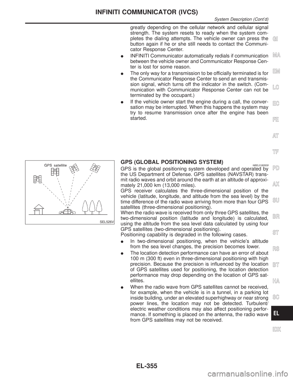
GPS (GLOBAL POSITIONING SYSTEM)NBEL0180S09GPS is the global positioning system developed and operated by
the US Department of Defense. GPS satellites (NAVSTAR) trans-
mit radio waves and orbit around the earth at an altitude of approxi-
mately 21,000 km (13,000 miles).
GPS receiver calculates the three-dimensional position of the
vehicle (latitude, longitude, and altitude from the sea level) by the
time difference of the radio wave arriving from more than four GPS
satellites (three-dimensional positioning).
When the radio wave is received from only three GPS satellites, the
two-dimensional position (latitude and longitude) is calculated,
using the altitude from the sea level data calculated by using four
GPS satellites (two-dimensional positioning).
Positioning capability is degraded in the following cases.
IIn two-dimensional positioning, when the vehicle's altitude
from the sea level changes, the precision becomes lower.
IThe location detection performance can have an error of about
100 m (300 ft) even in three-dimensional positioning with high
precision. Because the precision is influenced by the location
of GPS satellites used for positioning, the location detection
performance may drop depending on the location of GPS sat-
ellites.
IWhen the radio wave from GPS satellites cannot be received,
for example, when the vehicle is in a tunnel, in a parking lot
inside building, under an elevated superhighway or near strong
power lines, the location may not be detected. Turbulent/
electric weather conditions may also affect positioning perfor-
mance. If something is placed on the antenna, the radio wave
from GPS satellites may not be received.
GI
MA
EM
LC
EC
FE
AT
TF
PD
AX
SU
BR
ST
RS
BT
HA
SC
IDX
INFINITI COMMUNICATOR (IVCS)
System Description (Cont'd)
EL-355
Page 1571 of 2395
SEL683V
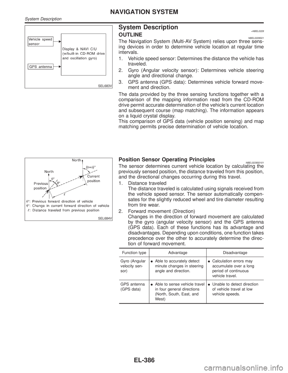
System Description=NBEL0228OUTLINENBEL0228S01The Navigation System (Multi-AV System) relies upon three sens-
ing devices in order to determine vehicle location at regular time
intervals.
1. Vehicle speed sensor: Determines the distance the vehicle has
traveled.
2. Gyro (Angular velocity sensor): Determines vehicle steering
angle and directional change.
3. GPS antenna (GPS data): Determines vehicle forward move-
ment and direction.
The data provided by the three sensing functions together with a
comparison of the mapping information read from the CD-ROM
drive permit accurate determination of the vehicle's current location
and subsequent course (map matching). The information appears
on a liquid crystal display.
This comparison of GPS data (vehicle position sensing) and map
matching permits precise determination of vehicle location.
SEL684V
Position Sensor Operating PrinciplesNBEL0228S0101The sensor determines current vehicle location by calculating the
previously sensed position, the distance traveled from this position,
and the directional changes occurring during this travel.
1. Distance traveled
The distance traveled is calculated using signals received from
the vehicle speed sensor. The sensor automatically compen-
sates for the slightly reduced wheel and tire diameter resulting
from tire wear.
2. Forward movement (Direction)
Changes in the direction of forward movement are calculated
by the gyro (angular velocity sensor) and the GPS antenna
(GPS data). Each of these functions has its advantage and
disadvantages. Depending upon conditions, one function takes
precedence over the other to accurately determine the direc-
tion of forward movement.
Function type Advantage Disadvantage
Gyro (Angular
velocity sen-
sor)IAble to accurately detect
minute changes in steering
angle and direction.ICalculation errors may
accumulate over a long
period of continuous
vehicle travel.
GPS antenna
(GPS data)IAble to sense vehicle travel
in four general directions
(North, South, East, and
West)IUnable to detect direction
of vehicle travel at low
vehicle speeds.
NAVIGATION SYSTEM
System Description
EL-386