2001 INFINITI QX4 change time
[x] Cancel search: change timePage 1866 of 2395

RHA865H
RHA330HA
3. Check Discharge AirNBHA0019S02031. Press MODE switch four times and D/F button.
2. Each position indicator should change shape.
RHA654F
3. Confirm that discharge air comes out according to the air dis-
tribution table at left.
Refer to ªDischarge Air Flowº (HA-25).
NOTE:
Confirm that the compressor clutch is engaged (visual inspection)
and intake door position is at FRESH when the DEF
is
selected.
Intake door position is checked in the next step.
If NG, go to trouble diagnosis procedure for mode door motor
(HA-75).
If OK, continue with next check.
GI
MA
EM
LC
EC
FE
AT
TF
PD
AX
SU
BR
ST
RS
BT
SC
EL
IDX
TROUBLE DIAGNOSES
Operational Check (Cont'd)
HA-67
Page 1916 of 2395
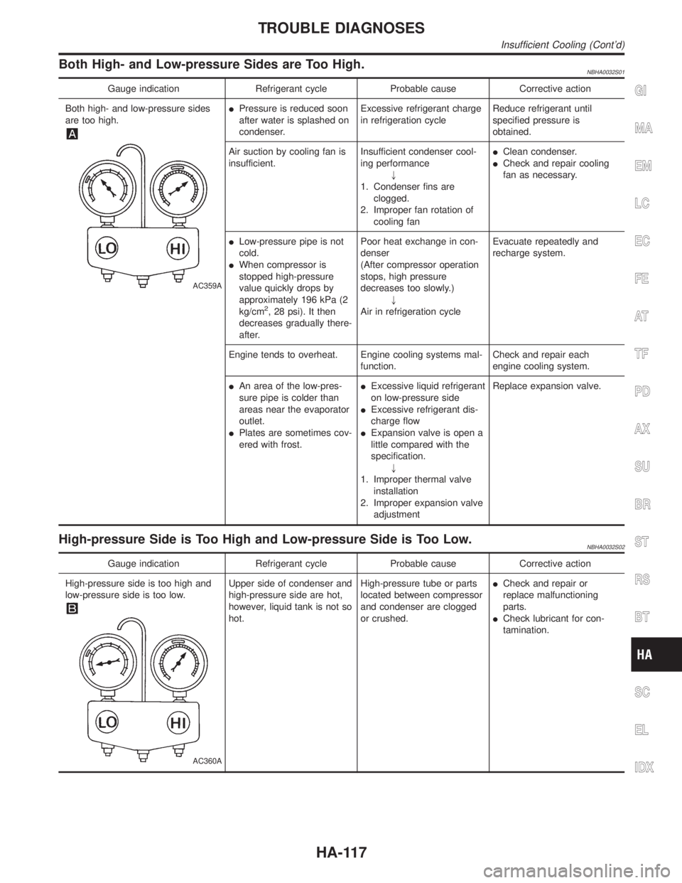
Both High- and Low-pressure Sides are Too High.NBHA0032S01
Gauge indication Refrigerant cycle Probable cause Corrective action
Both high- and low-pressure sides
are too high.
AC359A
IPressure is reduced soon
after water is splashed on
condenser.Excessive refrigerant charge
in refrigeration cycleReduce refrigerant until
specified pressure is
obtained.
Air suction by cooling fan is
insufficient.Insufficient condenser cool-
ing performance
"
1. Condenser fins are
clogged.
2. Improper fan rotation of
cooling fanIClean condenser.
ICheck and repair cooling
fan as necessary.
ILow-pressure pipe is not
cold.
IWhen compressor is
stopped high-pressure
value quickly drops by
approximately 196 kPa (2
kg/cm
2, 28 psi). It then
decreases gradually there-
after.Poor heat exchange in con-
denser
(After compressor operation
stops, high pressure
decreases too slowly.)
"
Air in refrigeration cycleEvacuate repeatedly and
recharge system.
Engine tends to overheat. Engine cooling systems mal-
function.Check and repair each
engine cooling system.
IAn area of the low-pres-
sure pipe is colder than
areas near the evaporator
outlet.
IPlates are sometimes cov-
ered with frost.IExcessive liquid refrigerant
on low-pressure side
IExcessive refrigerant dis-
charge flow
IExpansion valve is open a
little compared with the
specification.
"
1. Improper thermal valve
installation
2. Improper expansion valve
adjustmentReplace expansion valve.
High-pressure Side is Too High and Low-pressure Side is Too Low.NBHA0032S02
Gauge indication Refrigerant cycle Probable cause Corrective action
High-pressure side is too high and
low-pressure side is too low.
AC360A
Upper side of condenser and
high-pressure side are hot,
however, liquid tank is not so
hot.High-pressure tube or parts
located between compressor
and condenser are clogged
or crushed.ICheck and repair or
replace malfunctioning
parts.
ICheck lubricant for con-
tamination.
GI
MA
EM
LC
EC
FE
AT
TF
PD
AX
SU
BR
ST
RS
BT
SC
EL
IDX
TROUBLE DIAGNOSES
Insufficient Cooling (Cont'd)
HA-117
Page 1962 of 2395
Brake fluid change ...........................................BR-7
Brake fluid level .............................................MA-25
Brake fluid level and line check .......................BR-7
Brake hydraulic line ..........................................BR-9
Brake inspection ............................................MA-25
Brake lines and cables inspection .................MA-25
Brake lining wear temporary checking ..........MA-26
Brake master cylinder ....................................BR-16
Brake pedal ....................................................BR-14
Bulb specifications ........................................EL-456
Bumper, front ..................................................BT-12
Bumper, rear ...................................................BT-15
BYPS/V - Wiring diagram ....................EC-587, 594
C
Camshaft inspection ......................................EM-42
Camshaft position sensor (PHASE) .............EC-342
Canister-See EVAP canister ..........................EC-32
Center bearing assembly (propeller
shaft) .............................................................PD-9
Center bearing disassembly (propeller
shaft) .............................................................PD-7
Center case (Transfer) ..................................TF-123
CHARGE - Wiring diagram ............................SC-20
Charging system ............................................SC-19
Chassis and body maintenance ....................MA-21
CHIME - Wiring diagram...............................EL-127
CIGAR - Wiring diagram ...............................EL-148
Cigarette lighter.............................................EL-148
Circuit breaker.................................................EL-16
CKPS - Wiring diagram ................................EC-334
Closed loop control (Left bank) ....................EC-491
Closed loop control (Right bank) .................EC-491
Closed throttle position switch .....................EC-431
Clutch drum (Transfer) ..................................TF-125
Clutch force release limit adjustment .............TF-39
Clutch pressure switch (Transfer) .................TF-111
Coil spring (front)..............................................SU-8
Coil spring (rear) ............................................SU-18
Collision diagnosis..........................................RS-59
Combination lamp, front, removal and
installation ...................................................BT-12
Combination lamp, rear, removal and
installation ...................................................BT-35
Combination meter..........................................EL-94
Combination meter removal and instal-
lation - See Instrument panel ......................BT-21
Combination switch .........................................EL-28
COMPAS - Wiring diagram ...........................EL-111
Compass .......................................................EL-110
Component Location (auto A/C).....................HA-27
Compression pressure ...................................EM-14
Compressor clutch removal and
installation .................................................HA-150
Compressor precaution ....................................HA-6
Compressor special service tool ....................HA-10
Connecting rod...............................................EM-65
Connecting rod bearing clearance.................EM-69
Connecting rod bushing clearance ................EM-70Connector inspection .......................................GI-21
Console box - See Instrument panel ..............BT-21
CONSULT for ABS .........................................BR-43
CONSULT for all-mode 4WD ..........................TF-30
CONSULT for engine .....................................EC-81
CONSULT-II general information .....................GI-38
Control valve (A/T) ........................................AT-301
Control valve (Transfer) ................................TF-128
Converter housing installation .......................AT-278
Coolant mixture ratio......................................MA-12
Coolant replacement ......................................MA-14
Cooling circuit (engine) ...................................LC-10
``Crankcase emission control system -
See positive crankcase ventilation''............EC-38
Crankshaft ......................................................EM-67
Crankshaft position sensor (POS) ...............EC-334
Crankshaft position sensor (POS)
chipping ....................................................EC-517
Crankshaft position sensor (REF) ................EC-510
Cruise control - See ASCD ...........................EL-221
Cylinder block ................................................EM-61
Cylinder head .................................................EM-38
Cylinder head bolt tightening .........................EM-49
D
Data link connector for Consult......................EC-81
Daytime light system.......................................EL-46
Daytime running light - See Daytime
light system .................................................EL-46
DEF - Wiring diagram ...................................EL-153
Detonation sensor - See Knock sensor .......EC-328
Diagnostic trouble code (DTC) for OBD
system ....................................................EC-8, 60
Diagnostic trouble code (DTC) inspec-
tion priority chart .......................................EC-116
Differential carrier assembly.....................PD-30, 57
Differential carrier disassembly ......................PD-44
Differential gear oil replacement ....................MA-24
Dimensions ......................................................GI-43
D/LOCK - Wiring diagram .............................EL-256
Dome light - See Interior lamp .......................EL-88
Door glass .......................................................BT-18
Door lock .........................................................BT-18
Door mirror ......................................................BT-56
Door trim .........................................................BT-30
Door, front .......................................................BT-18
Door, rear ........................................................BT-20
Drive belt inspection ......................................MA-13
Drive chain (Transfer) ...................................TF-125
Drive pinion diff. inspection ......................PD-23, 47
Drive pinion height ...................................PD-25, 53
Drive plate runout ..........................................EM-70
Drive shaft (front)............................................AX-10
Dropping resistor (A/T) ..................................AT-167
DTC work support ..........................................EC-93
DTRL - Wiring diagram ...................................EL-51
GI
MA
EM
LC
EC
FE
AT
TF
PD
AX
SU
BR
ST
RS
BT
HA
SC
EL
ALPHABETICAL INDEX
IDX-3
Page 1999 of 2395

NBMA0003
General maintenance includes those items which should be checked during the normal day-to-day operation
of the vehicle. They are essential if the vehicle is to continue operating properly. The owners can perform
checks and inspections themselves or they can have their INFINITI dealers do them.
OUTSIDE THE VEHICLE
The maintenance items listed here should be performed from time to time, unless otherwise specified.
ItemReference page
TiresCheck the pressure with a gauge periodically when at a service station,
including the spare, and adjust to the specified pressure if necessary. Check
carefully for damage, cuts or excessive wear.Ð
Wheel nutsWhen checking the tires, make sure no nuts are missing, and check for any
loose nuts. Tighten if necessary.Ð
Tire rotationTires should be rotated every 12,000 km (7,500 miles). MA-24
Wheel alignment and
balanceIf the vehicle pulls to either side while driving on a straight and level road, or
if you detect uneven or abnormal tire wear, there may be a need for wheel
alignment. If the steering wheel or seat vibrates at normal highway speeds,
wheel balancing may be needed.MA-24, SU-6, ªFront
Wheel Alignmentº
Windshield wiper
bladesCheck for cracks or wear if they do not wipe properly. Ð
Doors and engine
hoodCheck that all doors and the engine hood operate smoothly as well as the
trunk lid and back hatch. Also make sure that all latches lock securely. Lubri-
cate if necessary. Make sure that the secondary latch keeps the hood from
opening when the primary latch is released.
When driving in areas using road salt or other corrosive materials, check
lubrication frequently.MA-27
INSIDE THE VEHICLE
The maintenance items listed here should be checked on a regular basis, such as when performing periodic maintenance, cleaning the
vehicle, etc.
ItemReference page
LampsMake sure that the headlamps, stop lamps, tail lamps, turn signal lamps, and
other lamps are all operating properly and installed securely. Also check
headlamp aim.Ð
Warning lamps and
buzzers/chimesMake sure that all warning lamps and buzzers/chimes are operating properly. Ð
Windshield wiper
and washerCheck that the wipers and washer operate properly and that the wipers do
not streak.Ð
Windshield defrosterCheck that the air comes out of the defroster outlets properly and in sufficient
quantity when operating the heater or air conditioning.Ð
Steering wheelCheck that it has the specified play. Be sure to check for changes in the
steering condition, such as excessive play, hard steering or strange noises.
Free play: Less than 35 mm (1.38 in)Ð
SeatsCheck seat position controls such as seat adjusters, seatback recliner, etc. to
make sure they operate smoothly and that all latches lock securely in every
position. Check that the head restrains move up and down smoothly and that
the locks (if equipped) hold securely in all latched positions. Check that the
latches lock securely for folding-down rear seatbacks.Ð
Seat beltsCheck that all parts of the seat belt system (e.g. buckles, anchors, adjusters
and retractors) operate properly and smoothly and are installed securely.
Check the belt webbing for cuts, fraying, wear or damage.MA-28, RS-7, ªSeat Belt
Inspectionº
BrakesCheck that the brake does not pull the vehicle to one side when applied. Ð
GENERAL MAINTENANCE
MA-4
Page 2013 of 2395
SMA096D
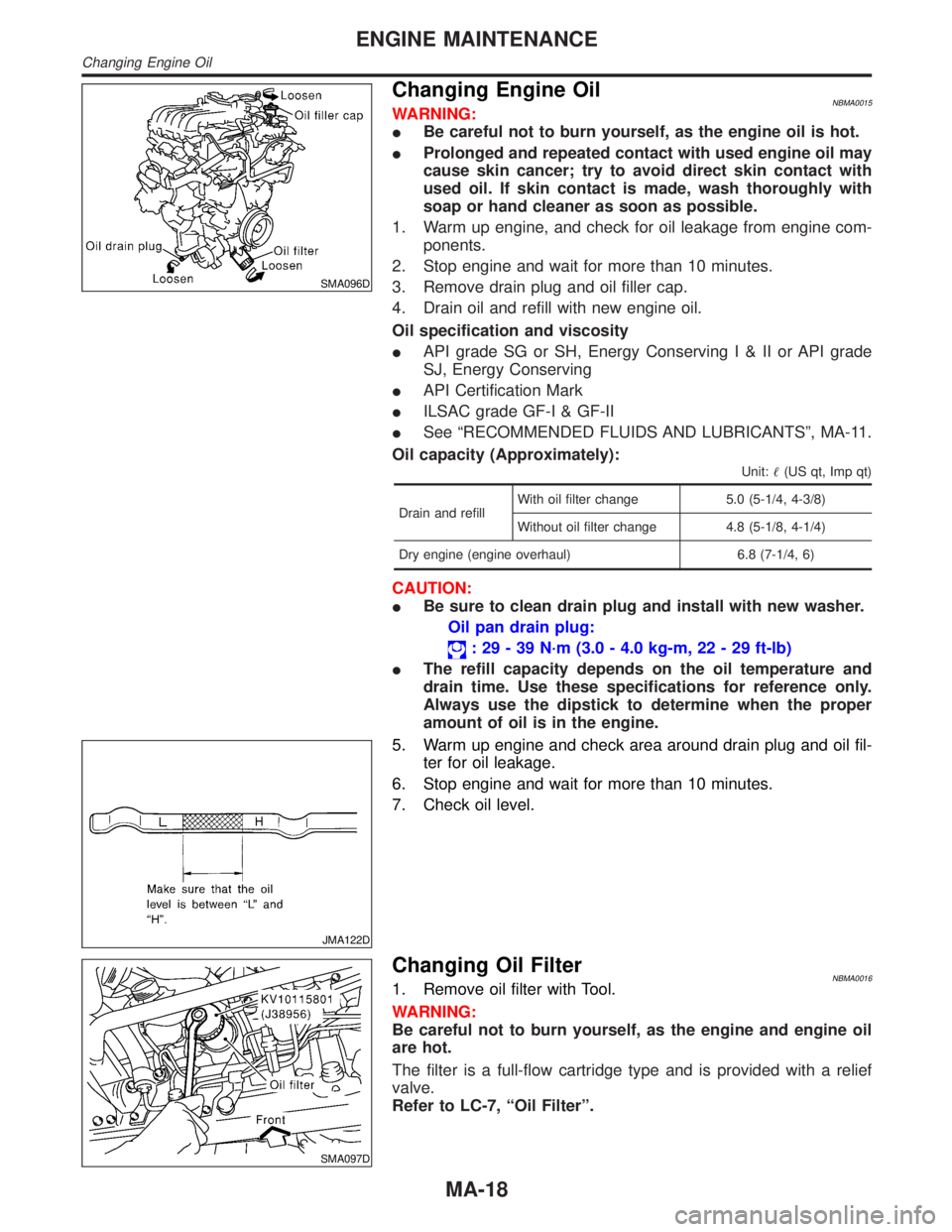
Changing Engine OilNBMA0015WARNING:
IBe careful not to burn yourself, as the engine oil is hot.
IProlonged and repeated contact with used engine oil may
cause skin cancer; try to avoid direct skin contact with
used oil. If skin contact is made, wash thoroughly with
soap or hand cleaner as soon as possible.
1. Warm up engine, and check for oil leakage from engine com-
ponents.
2. Stop engine and wait for more than 10 minutes.
3. Remove drain plug and oil filler cap.
4. Drain oil and refill with new engine oil.
Oil specification and viscosity
IAPI grade SG or SH, Energy ConservingI&IIorAPIgrade
SJ, Energy Conserving
IAPI Certification Mark
IILSAC grade GF-I & GF-II
ISee ªRECOMMENDED FLUIDS AND LUBRICANTSº, MA-11.
Oil capacity (Approximately):
Unit:(US qt, Imp qt)
Drain and refillWith oil filter change 5.0 (5-1/4, 4-3/8)
Without oil filter change 4.8 (5-1/8, 4-1/4)
Dry engine (engine overhaul) 6.8 (7-1/4, 6)
CAUTION:
IBe sure to clean drain plug and install with new washer.
Oil pan drain plug:
: 29 - 39 N´m (3.0 - 4.0 kg-m, 22 - 29 ft-lb)
IThe refill capacity depends on the oil temperature and
drain time. Use these specifications for reference only.
Always use the dipstick to determine when the proper
amount of oil is in the engine.
JMA122D
5. Warm up engine and check area around drain plug and oil fil-
ter for oil leakage.
6. Stop engine and wait for more than 10 minutes.
7. Check oil level.
SMA097D
Changing Oil FilterNBMA00161. Remove oil filter with Tool.
WARNING:
Be careful not to burn yourself, as the engine and engine oil
are hot.
The filter is a full-flow cartridge type and is provided with a relief
valve.
Refer to LC-7, ªOil Filterº.
ENGINE MAINTENANCE
Changing Engine Oil
MA-18
Page 2015 of 2395
: 20 - 29 N´m (2.0 - 3.0 kg-m, 14 - 22 ft-lb)
Use standard type spark plug for normal condition.
The hot type spark plug is suitable when fouling may occur with the
standard type spark plug such as:
Ifrequent engine starts
Ilow ambient temperatures
The cold type spark plug is suitable when spark knock may occur
with the standard type spark plug such as:
Iextended highway driving
Ifrequent high engine revolution
SMA773C
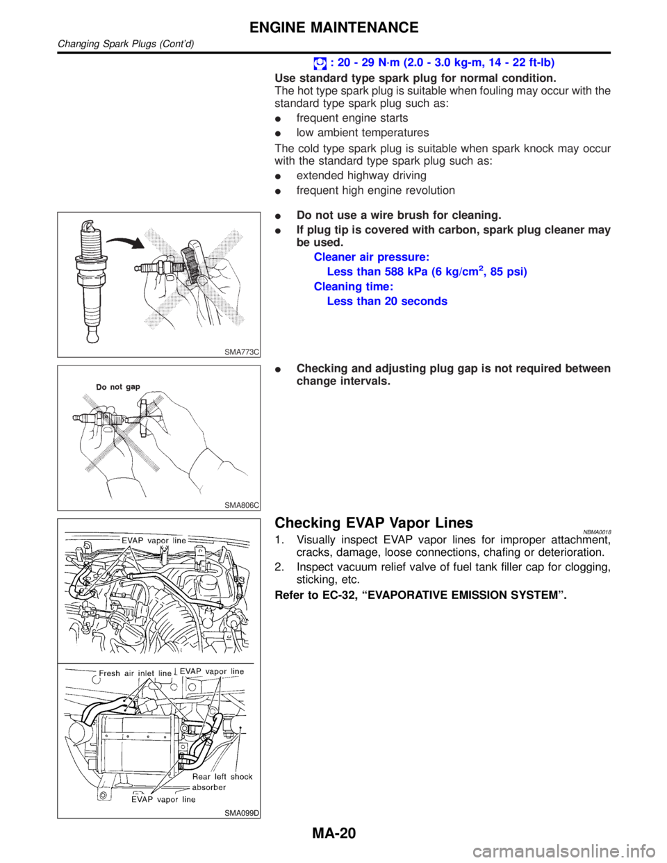
IDo not use a wire brush for cleaning.
IIf plug tip is covered with carbon, spark plug cleaner may
be used.
Cleaner air pressure:
Less than 588 kPa (6 kg/cm
2, 85 psi)
Cleaning time:
Less than 20 seconds
SMA806C
IChecking and adjusting plug gap is not required between
change intervals.
SMA099D
Checking EVAP Vapor LinesNBMA00181. Visually inspect EVAP vapor lines for improper attachment,
cracks, damage, loose connections, chafing or deterioration.
2. Inspect vacuum relief valve of fuel tank filler cap for clogging,
sticking, etc.
Refer to EC-32, ªEVAPORATIVE EMISSION SYSTEMº.
ENGINE MAINTENANCE
Changing Spark Plugs (Cont'd)
MA-20
Page 2060 of 2395
SPD560
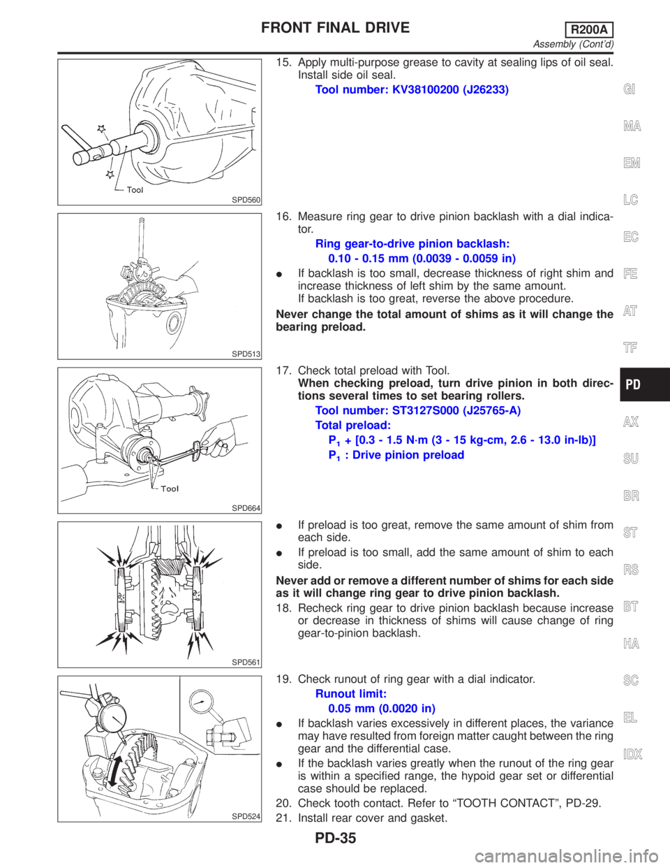
15. Apply multi-purpose grease to cavity at sealing lips of oil seal.
Install side oil seal.
Tool number: KV38100200 (J26233)
SPD513
16. Measure ring gear to drive pinion backlash with a dial indica-
tor.
Ring gear-to-drive pinion backlash:
0.10 - 0.15 mm (0.0039 - 0.0059 in)
IIf backlash is too small, decrease thickness of right shim and
increase thickness of left shim by the same amount.
If backlash is too great, reverse the above procedure.
Never change the total amount of shims as it will change the
bearing preload.
SPD664
17. Check total preload with Tool.
When checking preload, turn drive pinion in both direc-
tions several times to set bearing rollers.
Tool number: ST3127S000 (J25765-A)
Total preload:
P
1+ [0.3 - 1.5 N´m (3 - 15 kg-cm, 2.6 - 13.0 in-lb)]
P
1: Drive pinion preload
SPD561
IIf preload is too great, remove the same amount of shim from
each side.
IIf preload is too small, add the same amount of shim to each
side.
Never add or remove a different number of shims for each side
as it will change ring gear to drive pinion backlash.
18. Recheck ring gear to drive pinion backlash because increase
or decrease in thickness of shims will cause change of ring
gear-to-pinion backlash.
SPD524
19. Check runout of ring gear with a dial indicator.
Runout limit:
0.05 mm (0.0020 in)
IIf backlash varies excessively in different places, the variance
may have resulted from foreign matter caught between the ring
gear and the differential case.
IIf the backlash varies greatly when the runout of the ring gear
is within a specified range, the hypoid gear set or differential
case should be replaced.
20. Check tooth contact. Refer to ªTOOTH CONTACTº, PD-29.
21. Install rear cover and gasket.
GI
MA
EM
LC
EC
FE
AT
TF
AX
SU
BR
ST
RS
BT
HA
SC
EL
IDX
FRONT FINAL DRIVER200A
Assembly (Cont'd)
PD-35
Page 2119 of 2395
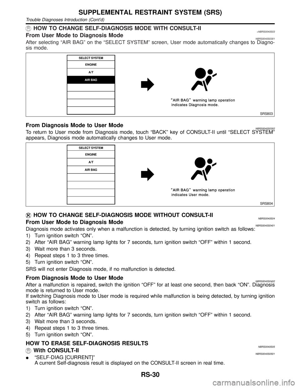
HOW TO CHANGE SELF-DIAGNOSIS MODE WITH CONSULT-II=NBRS0040S03From User Mode to Diagnosis ModeNBRS0040S0301After selecting ªAIR BAGº on the ªSELECT SYSTEMº screen, User mode automatically changes to Diagno-
sis mode.
SRS803
From Diagnosis Mode to User ModeNBRS0040S0302To return to User mode from Diagnosis mode, touch ªBACKº key of CONSULT-II until ªSELECT SYSTEMº
appears, Diagnosis mode automatically changes to User mode.
SRS804
HOW TO CHANGE SELF-DIAGNOSIS MODE WITHOUT CONSULT-IINBRS0040S04From User Mode to Diagnosis ModeNBRS0040S0401Diagnosis mode activates only when a malfunction is detected, by turning ignition switch as follows:
1) Turn ignition switch ªONº.
2) After ªAIR BAGº warning lamp lights for 7 seconds, turn ignition switch ªOFFº within 1 second.
3) Wait more than 3 seconds.
4) Repeat steps 1 to 3 three times.
5) Turn ignition switch ªONº.
SRS will not enter Diagnosis mode, if no malfunction is detected.
From Diagnosis Mode to User ModeNBRS0040S0402After a malfunction is repaired, switch the ignition ªOFFº for at least one second, then back ªONº. Diagnosis
mode is returned to User mode.
If switching Diagnosis mode to User mode is required while malfunction is being detected, by turning ignition
switch as follows:
1) Turn ignition switch ªONº.
2) After ªAIR BAGº warning lamp lights for 7 seconds, turn ignition switch ªOFFº within 1 second.
3) Wait more than 3 seconds.
4) Repeat steps 1 to 3 three times.
5) Turn ignition switch ªONº.
HOW TO ERASE SELF-DIAGNOSIS RESULTSNBRS0040S05With CONSULT-IINBRS0040S0501IªSELF-DIAG [CURRENT]º
A current Self-diagnosis result is displayed on the CONSULT-II screen in real time.
SUPPLEMENTAL RESTRAINT SYSTEM (SRS)
Trouble Diagnoses Introduction (Cont'd)
RS-30