2001 INFINITI QX4 window
[x] Cancel search: windowPage 1343 of 2395
SEL265
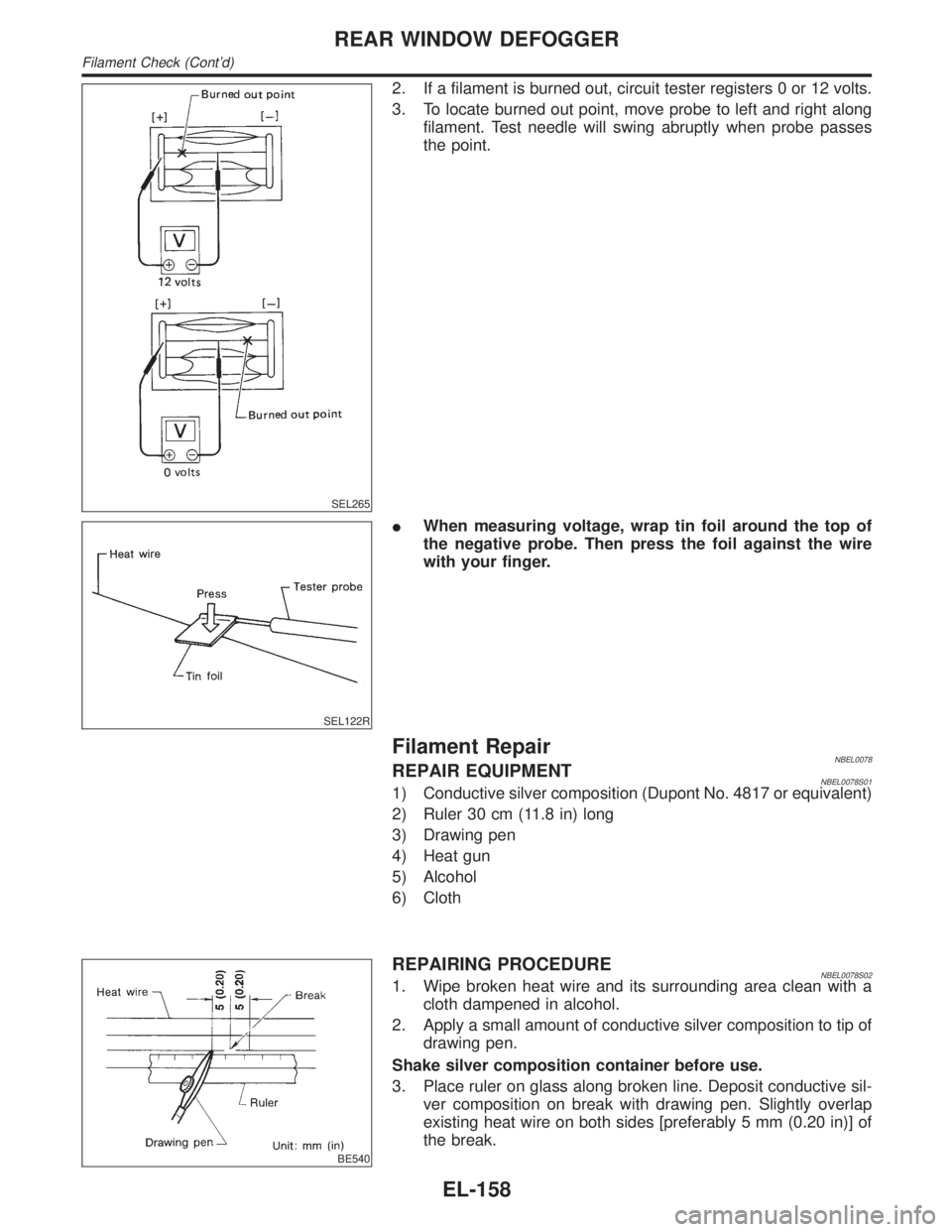
2. If a filament is burned out, circuit tester registers 0 or 12 volts.
3. To locate burned out point, move probe to left and right along
filament. Test needle will swing abruptly when probe passes
the point.
SEL122R
IWhen measuring voltage, wrap tin foil around the top of
the negative probe. Then press the foil against the wire
with your finger.
Filament RepairNBEL0078REPAIR EQUIPMENTNBEL0078S011) Conductive silver composition (Dupont No. 4817 or equivalent)
2) Ruler 30 cm (11.8 in) long
3) Drawing pen
4) Heat gun
5) Alcohol
6) Cloth
BE540
REPAIRING PROCEDURENBEL0078S021. Wipe broken heat wire and its surrounding area clean with a
cloth dampened in alcohol.
2. Apply a small amount of conductive silver composition to tip of
drawing pen.
Shake silver composition container before use.
3. Place ruler on glass along broken line. Deposit conductive sil-
ver composition on break with drawing pen. Slightly overlap
existing heat wire on both sides [preferably 5 mm (0.20 in)] of
the break.
REAR WINDOW DEFOGGER
Filament Check (Cont'd)
EL-158
Page 1344 of 2395
SEL012D
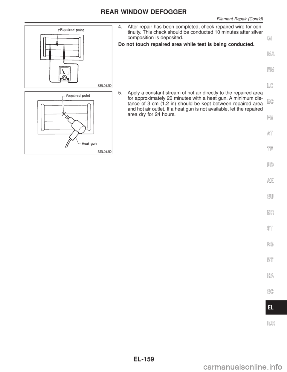
4. After repair has been completed, check repaired wire for con-
tinuity. This check should be conducted 10 minutes after silver
composition is deposited.
Do not touch repaired area while test is being conducted.
SEL013D
5. Apply a constant stream of hot air directly to the repaired area
for approximately 20 minutes with a heat gun. A minimum dis-
tance of 3 cm (1.2 in) should be kept between repaired area
and hot air outlet. If a heat gun is not available, let the repaired
area dry for 24 hours.
GI
MA
EM
LC
EC
FE
AT
TF
PD
AX
SU
BR
ST
RS
BT
HA
SC
IDX
REAR WINDOW DEFOGGER
Filament Repair (Cont'd)
EL-159
Page 1351 of 2395
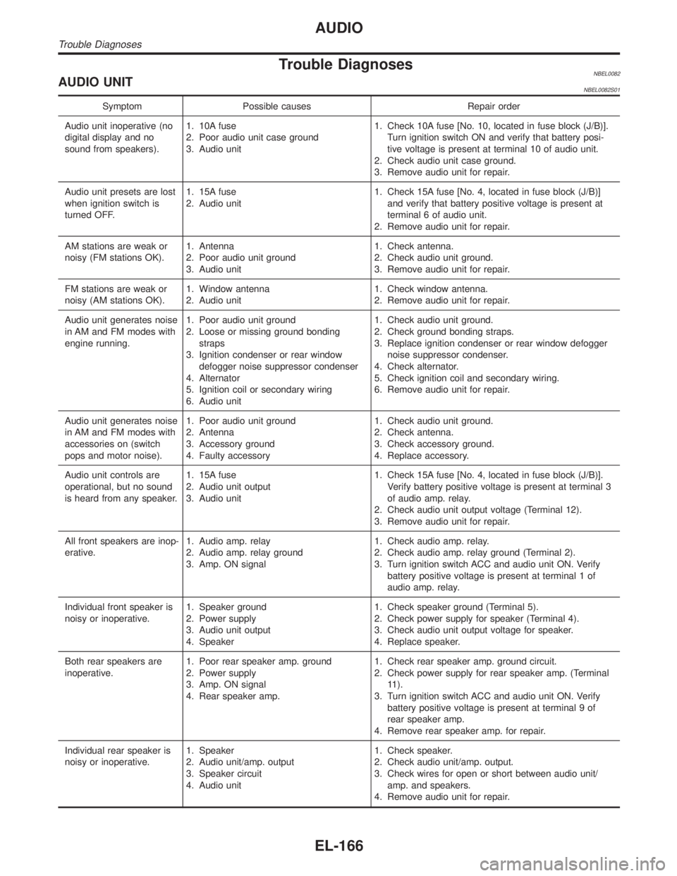
Trouble DiagnosesNBEL0082AUDIO UNITNBEL0082S01
Symptom Possible causes Repair order
Audio unit inoperative (no
digital display and no
sound from speakers).1. 10A fuse
2. Poor audio unit case ground
3. Audio unit1. Check 10A fuse [No. 10, located in fuse block (J/B)].
Turn ignition switch ON and verify that battery posi-
tive voltage is present at terminal 10 of audio unit.
2. Check audio unit case ground.
3. Remove audio unit for repair.
Audio unit presets are lost
when ignition switch is
turned OFF.1. 15A fuse
2. Audio unit1. Check 15A fuse [No. 4, located in fuse block (J/B)]
and verify that battery positive voltage is present at
terminal 6 of audio unit.
2. Remove audio unit for repair.
AM stations are weak or
noisy (FM stations OK).1. Antenna
2. Poor audio unit ground
3. Audio unit1. Check antenna.
2. Check audio unit ground.
3. Remove audio unit for repair.
FM stations are weak or
noisy (AM stations OK).1. Window antenna
2. Audio unit1. Check window antenna.
2. Remove audio unit for repair.
Audio unit generates noise
in AM and FM modes with
engine running.1. Poor audio unit ground
2. Loose or missing ground bonding
straps
3. Ignition condenser or rear window
defogger noise suppressor condenser
4. Alternator
5. Ignition coil or secondary wiring
6. Audio unit1. Check audio unit ground.
2. Check ground bonding straps.
3. Replace ignition condenser or rear window defogger
noise suppressor condenser.
4. Check alternator.
5. Check ignition coil and secondary wiring.
6. Remove audio unit for repair.
Audio unit generates noise
in AM and FM modes with
accessories on (switch
pops and motor noise).1. Poor audio unit ground
2. Antenna
3. Accessory ground
4. Faulty accessory1. Check audio unit ground.
2. Check antenna.
3. Check accessory ground.
4. Replace accessory.
Audio unit controls are
operational, but no sound
is heard from any speaker.1. 15A fuse
2. Audio unit output
3. Audio unit1. Check 15A fuse [No. 4, located in fuse block (J/B)].
Verify battery positive voltage is present at terminal 3
of audio amp. relay.
2. Check audio unit output voltage (Terminal 12).
3. Remove audio unit for repair.
All front speakers are inop-
erative.1. Audio amp. relay
2. Audio amp. relay ground
3. Amp. ON signal1. Check audio amp. relay.
2. Check audio amp. relay ground (Terminal 2).
3. Turn ignition switch ACC and audio unit ON. Verify
battery positive voltage is present at terminal 1 of
audio amp. relay.
Individual front speaker is
noisy or inoperative.1. Speaker ground
2. Power supply
3. Audio unit output
4. Speaker1. Check speaker ground (Terminal 5).
2. Check power supply for speaker (Terminal 4).
3. Check audio unit output voltage for speaker.
4. Replace speaker.
Both rear speakers are
inoperative.1. Poor rear speaker amp. ground
2. Power supply
3. Amp. ON signal
4. Rear speaker amp.1. Check rear speaker amp. ground circuit.
2. Check power supply for rear speaker amp. (Terminal
11).
3. Turn ignition switch ACC and audio unit ON. Verify
battery positive voltage is present at terminal 9 of
rear speaker amp.
4. Remove rear speaker amp. for repair.
Individual rear speaker is
noisy or inoperative.1. Speaker
2. Audio unit/amp. output
3. Speaker circuit
4. Audio unit1. Check speaker.
2. Check audio unit/amp. output.
3. Check wires for open or short between audio unit/
amp. and speakers.
4. Remove audio unit for repair.
AUDIO
Trouble Diagnoses
EL-166
Page 1358 of 2395
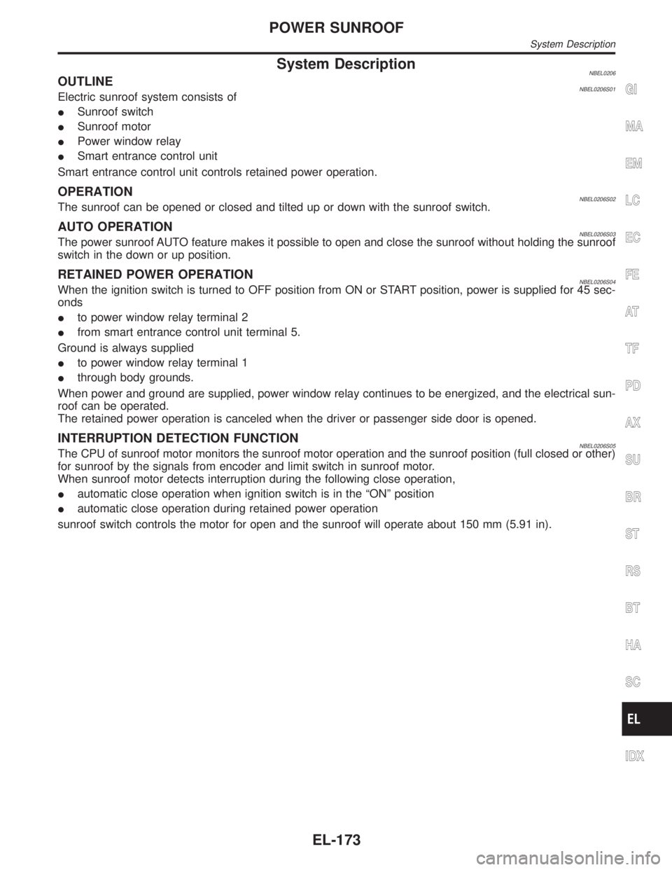
System DescriptionNBEL0206OUTLINENBEL0206S01Electric sunroof system consists of
ISunroof switch
ISunroof motor
IPower window relay
ISmart entrance control unit
Smart entrance control unit controls retained power operation.
OPERATIONNBEL0206S02The sunroof can be opened or closed and tilted up or down with the sunroof switch.
AUTO OPERATIONNBEL0206S03The power sunroof AUTO feature makes it possible to open and close the sunroof without holding the sunroof
switch in the down or up position.
RETAINED POWER OPERATIONNBEL0206S04When the ignition switch is turned to OFF position from ON or START position, power is supplied for 45 sec-
onds
Ito power window relay terminal 2
Ifrom smart entrance control unit terminal 5.
Ground is always supplied
Ito power window relay terminal 1
Ithrough body grounds.
When power and ground are supplied, power window relay continues to be energized, and the electrical sun-
roof can be operated.
The retained power operation is canceled when the driver or passenger side door is opened.
INTERRUPTION DETECTION FUNCTIONNBEL0206S05The CPU of sunroof motor monitors the sunroof motor operation and the sunroof position (full closed or other)
for sunroof by the signals from encoder and limit switch in sunroof motor.
When sunroof motor detects interruption during the following close operation,
Iautomatic close operation when ignition switch is in the ªONº position
Iautomatic close operation during retained power operation
sunroof switch controls the motor for open and the sunroof will operate about 150 mm (5.91 in).
GI
MA
EM
LC
EC
FE
AT
TF
PD
AX
SU
BR
ST
RS
BT
HA
SC
IDX
POWER SUNROOF
System Description
EL-173
Page 1361 of 2395
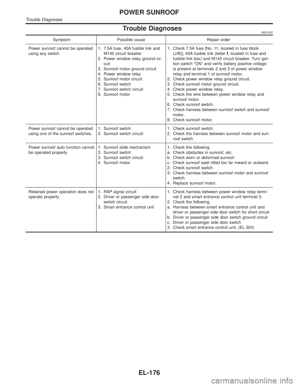
Trouble DiagnosesNBEL0207
Symptom Possible cause Repair order
Power sunroof cannot be operated
using any switch.1. 7.5A fuse, 40A fusible link and
M145 circuit breaker
2. Power window relay ground cir-
cuit
3. Sunroof motor ground circuit
4. Power window relay
5. Sunroof motor circuit
6. Sunroof switch
7. Sunroof switch circuit
8. Sunroof motor1. Check 7.5A fuse [No. 11, located in fuse block
(J/B)], 40A fusible link (letterf, located in fuse and
fusible link box) and M145 circuit breaker. Turn igni-
tion switch ªONº and verify battery positive voltage
is present at terminals 2 and 3 of power window
relay and terminal 1 of sunroof motor.
2. Check power window relay ground circuit.
3. Check sunroof motor ground circuit.
4. Check power window relay.
5. Check the wire between power window relay and
sunroof motor.
6. Check sunroof switch.
7. Check harness between sunroof switch and sunroof
motor.
8. Check sunroof motor.
Power sunroof cannot be operated
using one of the sunroof switches.1. Sunroof switch
2. Sunroof switch circuit1. Check sunroof switch.
2. Check the harness between sunroof motor and sun-
roof switch.
Power sunroof auto function cannot
be operated properly.1. Sunroof slide mechanism
2. Sunroof switch
3. Sunroof switch circuit
4. Sunroof motor1. Check the following.
a. Check obstacles in sunroof, etc.
b. Check worn or deformed sunroof.
c. Check sunroof sash tilted too far inward or outward.
2. Check sunroof switch.
3. Check harness between sunroof motor and sunroof
switch.
4. Replace sunroof motor.
Retained power operation does not
operate properly.1. RAP signal circuit
2. Driver or passenger side door
switch circuit
3. Smart entrance control unit1. Check harness between power window relay termi-
nal 2 and smart entrance control unit terminal 5.
2. Check the following.
a. Harness between smart entrance control unit and
driver or passenger side door switch for short circuit
b. Driver or passenger side door switch ground circuit
c. Driver or passenger side door switch
3. Check smart entrance control unit. (EL-324)
POWER SUNROOF
Trouble Diagnoses
EL-176
Page 1426 of 2395
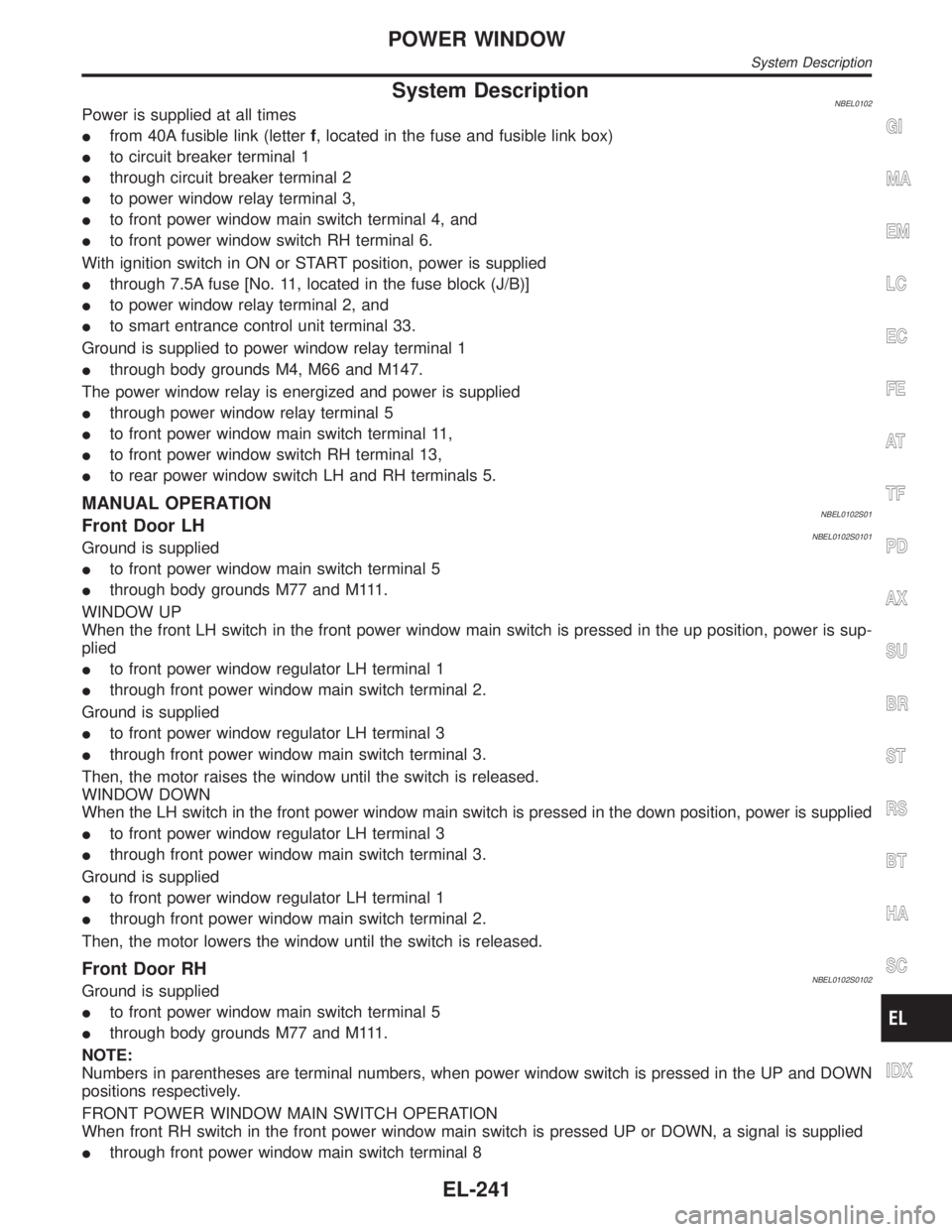
System DescriptionNBEL0102Power is supplied at all times
Ifrom 40A fusible link (letterf, located in the fuse and fusible link box)
Ito circuit breaker terminal 1
Ithrough circuit breaker terminal 2
Ito power window relay terminal 3,
Ito front power window main switch terminal 4, and
Ito front power window switch RH terminal 6.
With ignition switch in ON or START position, power is supplied
Ithrough 7.5A fuse [No. 11, located in the fuse block (J/B)]
Ito power window relay terminal 2, and
Ito smart entrance control unit terminal 33.
Ground is supplied to power window relay terminal 1
Ithrough body grounds M4, M66 and M147.
The power window relay is energized and power is supplied
Ithrough power window relay terminal 5
Ito front power window main switch terminal 11,
Ito front power window switch RH terminal 13,
Ito rear power window switch LH and RH terminals 5.
MANUAL OPERATIONNBEL0102S01Front Door LHNBEL0102S0101Ground is supplied
Ito front power window main switch terminal 5
Ithrough body grounds M77 and M111.
WINDOW UP
When the front LH switch in the front power window main switch is pressed in the up position, power is sup-
plied
Ito front power window regulator LH terminal 1
Ithrough front power window main switch terminal 2.
Ground is supplied
Ito front power window regulator LH terminal 3
Ithrough front power window main switch terminal 3.
Then, the motor raises the window until the switch is released.
WINDOW DOWN
When the LH switch in the front power window main switch is pressed in the down position, power is supplied
Ito front power window regulator LH terminal 3
Ithrough front power window main switch terminal 3.
Ground is supplied
Ito front power window regulator LH terminal 1
Ithrough front power window main switch terminal 2.
Then, the motor lowers the window until the switch is released.
Front Door RHNBEL0102S0102Ground is supplied
Ito front power window main switch terminal 5
Ithrough body grounds M77 and M111.
NOTE:
Numbers in parentheses are terminal numbers, when power window switch is pressed in the UP and DOWN
positions respectively.
FRONT POWER WINDOW MAIN SWITCH OPERATION
When front RH switch in the front power window main switch is pressed UP or DOWN, a signal is supplied
Ithrough front power window main switch terminal 8
GI
MA
EM
LC
EC
FE
AT
TF
PD
AX
SU
BR
ST
RS
BT
HA
SC
IDX
POWER WINDOW
System Description
EL-241
Page 1427 of 2395
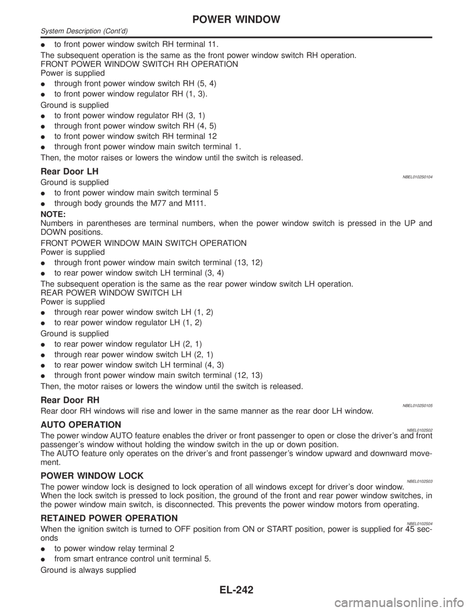
Ito front power window switch RH terminal 11.
The subsequent operation is the same as the front power window switch RH operation.
FRONT POWER WINDOW SWITCH RH OPERATION
Power is supplied
Ithrough front power window switch RH (5, 4)
Ito front power window regulator RH (1, 3).
Ground is supplied
Ito front power window regulator RH (3, 1)
Ithrough front power window switch RH (4, 5)
Ito front power window switch RH terminal 12
Ithrough front power window main switch terminal 1.
Then, the motor raises or lowers the window until the switch is released.
Rear Door LHNBEL0102S0104Ground is supplied
Ito front power window main switch terminal 5
Ithrough body grounds the M77 and M111.
NOTE:
Numbers in parentheses are terminal numbers, when the power window switch is pressed in the UP and
DOWN positions.
FRONT POWER WINDOW MAIN SWITCH OPERATION
Power is supplied
Ithrough front power window main switch terminal (13, 12)
Ito rear power window switch LH terminal (3, 4)
The subsequent operation is the same as the rear power window switch LH operation.
REAR POWER WINDOW SWITCH LH
Power is supplied
Ithrough rear power window switch LH (1, 2)
Ito rear power window regulator LH (1, 2)
Ground is supplied
Ito rear power window regulator LH (2, 1)
Ithrough rear power window switch LH (2, 1)
Ito rear power window switch LH terminal (4, 3)
Ithrough front power window main switch terminal (12, 13)
Then, the motor raises or lowers the window until the switch is released.
Rear Door RHNBEL0102S0105Rear door RH windows will rise and lower in the same manner as the rear door LH window.
AUTO OPERATIONNBEL0102S02The power window AUTO feature enables the driver or front passenger to open or close the driver's and front
passenger's window without holding the window switch in the up or down position.
The AUTO feature only operates on the driver's and front passenger's window upward and downward move-
ment.
POWER WINDOW LOCKNBEL0102S03The power window lock is designed to lock operation of all windows except for driver's door window.
When the lock switch is pressed to lock position, the ground of the front and rear power window switches, in
the power window main switch, is disconnected. This prevents the power window motors from operating.
RETAINED POWER OPERATIONNBEL0102S04When the ignition switch is turned to OFF position from ON or START position, power is supplied for 45 sec-
onds
Ito power window relay terminal 2
Ifrom smart entrance control unit terminal 5.
Ground is always supplied
POWER WINDOW
System Description (Cont'd)
EL-242
Page 1428 of 2395
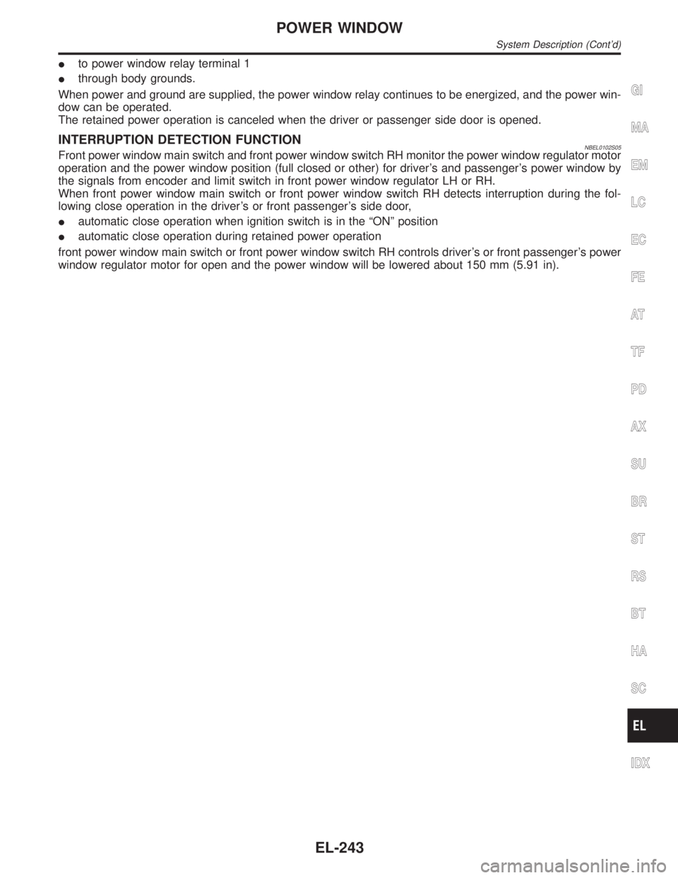
Ito power window relay terminal 1
Ithrough body grounds.
When power and ground are supplied, the power window relay continues to be energized, and the power win-
dow can be operated.
The retained power operation is canceled when the driver or passenger side door is opened.
INTERRUPTION DETECTION FUNCTIONNBEL0102S05Front power window main switch and front power window switch RH monitor the power window regulator motor
operation and the power window position (full closed or other) for driver's and passenger's power window by
the signals from encoder and limit switch in front power window regulator LH or RH.
When front power window main switch or front power window switch RH detects interruption during the fol-
lowing close operation in the driver's or front passenger's side door,
Iautomatic close operation when ignition switch is in the ªONº position
Iautomatic close operation during retained power operation
front power window main switch or front power window switch RH controls driver's or front passenger's power
window regulator motor for open and the power window will be lowered about 150 mm (5.91 in).
GI
MA
EM
LC
EC
FE
AT
TF
PD
AX
SU
BR
ST
RS
BT
HA
SC
IDX
POWER WINDOW
System Description (Cont'd)
EL-243