2001 INFINITI QX4 window
[x] Cancel search: windowPage 666 of 2395
![INFINITI QX4 2001 Factory Service Manual TERMI-
NAL
NO.WIRE
COLORITEM CONDITION DATA (DC Voltage)
42 B/Y Start signal[Ignition switch ªONº]Approximately 0V
[Ignition switch ªSTARTº]9 - 12V
43 R Ignition switch[Ignition switch ªOFFº]0V
INFINITI QX4 2001 Factory Service Manual TERMI-
NAL
NO.WIRE
COLORITEM CONDITION DATA (DC Voltage)
42 B/Y Start signal[Ignition switch ªONº]Approximately 0V
[Ignition switch ªSTARTº]9 - 12V
43 R Ignition switch[Ignition switch ªOFFº]0V](/manual-img/42/57027/w960_57027-665.png)
TERMI-
NAL
NO.WIRE
COLORITEM CONDITION DATA (DC Voltage)
42 B/Y Start signal[Ignition switch ªONº]Approximately 0V
[Ignition switch ªSTARTº]9 - 12V
43 R Ignition switch[Ignition switch ªOFFº]0V
[Ignition switch ªONº]BATTERY VOLTAGE
(11 - 14V)
44 L PNP switch[Ignition switch ªONº]
IGear position is ªPº or ªNº.Approximately 0V
[Ignition switch ªONº]
IExcept the above gear positionBATTERY VOLTAGE
(11 - 14V)
45 B/RAir conditioner switch
signal[Engine is running]
IBoth A/C switch and blower switch are ªONº.Approximately 0V
[Engine is running]
IA/C switch is ªOFFº.Approximately 5V
47 R/BPower steering oil
pressure switch[Engine is running]
ISteering wheel is being turned.0 - 1.0V
[Engine is running]
ISteering wheel is not being turned.Approximately 5V
48 B ECM ground[Engine is running]
IIdle speedEngine ground
51 BR A/C cut signal[Engine is running]
IAir conditioner is operating.0 - 0.5V
52 PU Electrical load signal[Engine is running]
IRear window defogger: ON
IHi-beam headlamp: ONBATTERY VOLTAGE
(11 - 14V)
[Engine is running]
IElectrical load: OFF0V
55 W/BSwirl control valve con-
trol vacuum check
switch[Engine is running]
IIdle speed
IEngine coolant temperature is between 15 to
50ÉC (59 to 122ÉF).Approximately 5V
[Engine is running]
IIdle speed
IEngine coolant temperature is above 55ÉC
(131ÉF).0 - 1.0V
56 OR/LThrottle position switch
(Closed position)[Engine is running]
IAccelerator pedal fully releasedBATTERY VOLTAGE
(11 - 14V)
[Engine is running]
IAccelerator pedal depressedApproximately 0V
57 B ECM ground[Engine is running]
IIdle speedEngine ground
58 B/P Sensors' ground[Engine is running]
IWarm-up condition
IIdle speedApproximately 0V
59 BFuel level sensor
ground[Engine is running]
IIdle speedApproximately 0V
GI
MA
EM
LC
FE
AT
TF
PD
AX
SU
BR
ST
RS
BT
HA
SC
EL
IDX
TROUBLE DIAGNOSIS Ð GENERAL DESCRIPTION
ECM Terminals and Reference Value (Cont'd)
EC-131
Page 671 of 2395

DescriptionNBEC0717The specification (SP) value indicates the tolerance of the value that is displayed in ªDATA MONITOR (SPEC)º
mode of CONSULT-II during normal operation of the Engine Control System. When the value in ªDATA MONI-
TOR (SPEC)º mode is within the SP value, the Engine Control System is confirmed OK. When the value in
ªDATA MONITOR (SPEC)º mode is NOT within the SP value, the Engine Control System may have one or
more malfunctions.
The SP value is used to detect malfunctions that may affect the Engine Control System, but will not light the
MIL.
The SP value will be displayed for the following three items:
IB/FUEL SCHDL (The fuel injection pulse width programmed into ECM prior to any learned on board cor-
rection)
IA/F ALPHA-B1/B2 (The mean value of air-fuel ratio feedback correction factor per cycle)
IMAS A/F SE-B1 (The signal voltage of the mass air flow sensor)
Testing ConditionNBEC0718IVehicle driven distance: More than 5,000 km (3,100 miles)
IBarometric pressure: 101.3 kPa (760.0 mmHg, 29.92 inHg)±3 kPa (22.5 mmHg, 0.89 inHg)
IAtmospheric temperature: 20 - 30ÉC (68 - 86ÉF)
IEngine coolant temperature: 75 - 95ÉC (167 - 203ÉF)
ITransmission: Warmed-up*1
IElectrical load: Not applied*2
IEngine speed: Idle
*1: For A/T models, after the engine is warmed up to normal operating temperature, drive vehicle until ªFLUID
TEMP SEº (A/T fluid temperature sensor signal) indicates less than 0.9V.
*2: Rear window defogger switch, air conditioner switch, lighting switch are ªOFFº. Cooling fans are not oper-
ating. Steering wheel is straight ahead.
SEF601Z
Inspection ProcedureNBEC0719NOTE:
Perform ªDATA MONITOR (SPEC)º mode in maximum scale dis-
play.
1. Perform ªBasic Inspectionº, EC-101.
2. Confirm that the testing conditions indicated above are met.
3. Select ªB/FUEL SCHDLº, ªA/F ALPHA-B1º, ªA/F ALPHA-B2º
and ªMAS A/F SE-B1º in ªDATA MONITOR (SPEC)º mode with
CONSULT-II.
4. Make sure that monitor items are within the SP value.
5. If NG, go to ªDiagnostic Procedureº, EC-137.
TROUBLE DIAGNOSIS Ð SPECIFICATION VALUE
Description
EC-136
Page 1098 of 2395

SEF355X
Overall Function CheckNBEC0336Use this procedure to check the overall monitoring function of the
EVAP control system purge flow monitoring. During this check, a
1st trip DTC might not be confirmed.
WITH GSTNBEC0336S011) Lift up drive wheels.
2) Start engine (TCS switch ªOFFº) and warm it up to normal
operating temperature.
3) Turn ignition switch ªOFFº, wait at least 10 seconds.
4) Start engine and wait at least 70 seconds.
5) Set voltmeter probes to ECM terminals 84 (EVAP control sys-
tem pressure sensor signal) and ground.
6) Check EVAP control system pressure sensor value at idle
speed and note it.
7) Establish and maintain the following conditions for at least 1
minute.
Air conditioner switch ON
Steering wheel Fully turned
Headlamp switch ON
Rear window defogger switch ON
Engine speed Approx. 3,000 rpm
Gear position Any position other than ªPº, ªNº or ªRº
8) Verify that EVAP control system pressure sensor value stays
0.1V less than the value at idle speed (measured at step 6) for
at least 1 second.
9) If NG, go to ªDiagnostic Procedureº, EC-564.
GI
MA
EM
LC
FE
AT
TF
PD
AX
SU
BR
ST
RS
BT
HA
SC
EL
IDX
DTC P1447 EVAPORATIVE EMISSION (EVAP) CONTROL SYSTEM PURGE
FLOW MONITORING
Overall Function Check
EC-563
Page 1178 of 2395
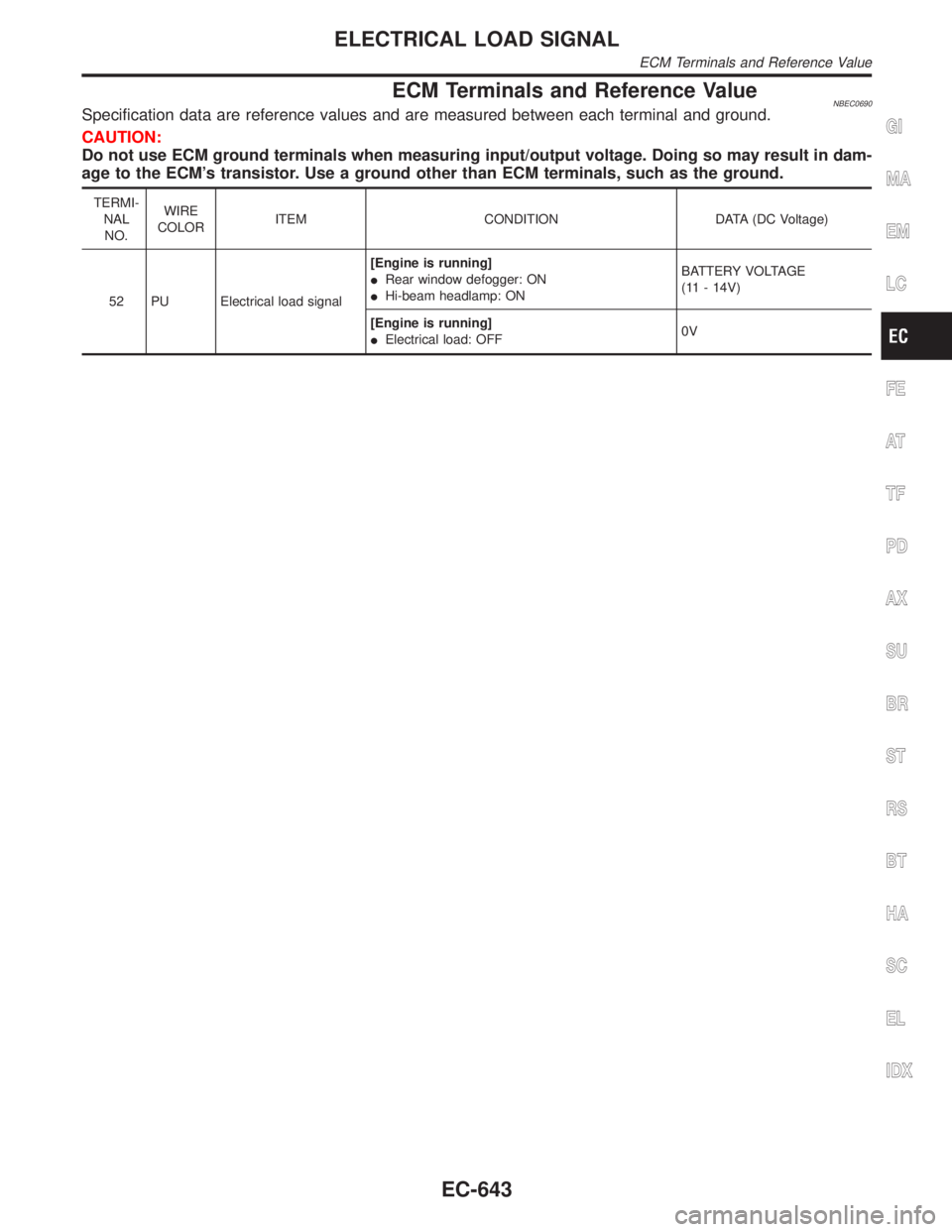
ECM Terminals and Reference ValueNBEC0690Specification data are reference values and are measured between each terminal and ground.
CAUTION:
Do not use ECM ground terminals when measuring input/output voltage. Doing so may result in dam-
age to the ECM's transistor. Use a ground other than ECM terminals, such as the ground.
TERMI-
NAL
NO.WIRE
COLORITEM CONDITION DATA (DC Voltage)
52 PU Electrical load signal[Engine is running]
IRear window defogger: ON
IHi-beam headlamp: ONBATTERY VOLTAGE
(11 - 14V)
[Engine is running]
IElectrical load: OFF0V
GI
MA
EM
LC
FE
AT
TF
PD
AX
SU
BR
ST
RS
BT
HA
SC
EL
IDX
ELECTRICAL LOAD SIGNAL
ECM Terminals and Reference Value
EC-643
Page 1180 of 2395
Diagnostic ProcedureNBEC0605
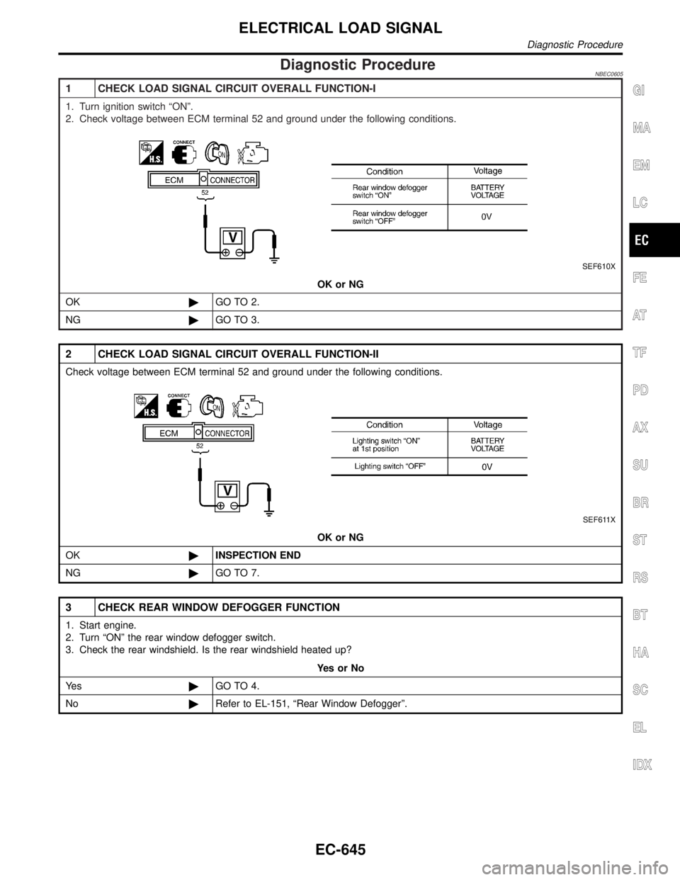
1 CHECK LOAD SIGNAL CIRCUIT OVERALL FUNCTION-I
1. Turn ignition switch ªONº.
2. Check voltage between ECM terminal 52 and ground under the following conditions.
SEF610X
OK or NG
OK©GO TO 2.
NG©GO TO 3.
2 CHECK LOAD SIGNAL CIRCUIT OVERALL FUNCTION-II
Check voltage between ECM terminal 52 and ground under the following conditions.
SEF611X
OK or NG
OK©INSPECTION END
NG©GO TO 7.
3 CHECK REAR WINDOW DEFOGGER FUNCTION
1. Start engine.
2. Turn ªONº the rear window defogger switch.
3. Check the rear windshield. Is the rear windshield heated up?
YesorNo
Ye s©GO TO 4.
No©Refer to EL-151, ªRear Window Defoggerº.
GI
MA
EM
LC
FE
AT
TF
PD
AX
SU
BR
ST
RS
BT
HA
SC
EL
IDX
ELECTRICAL LOAD SIGNAL
Diagnostic Procedure
EC-645
Page 1181 of 2395
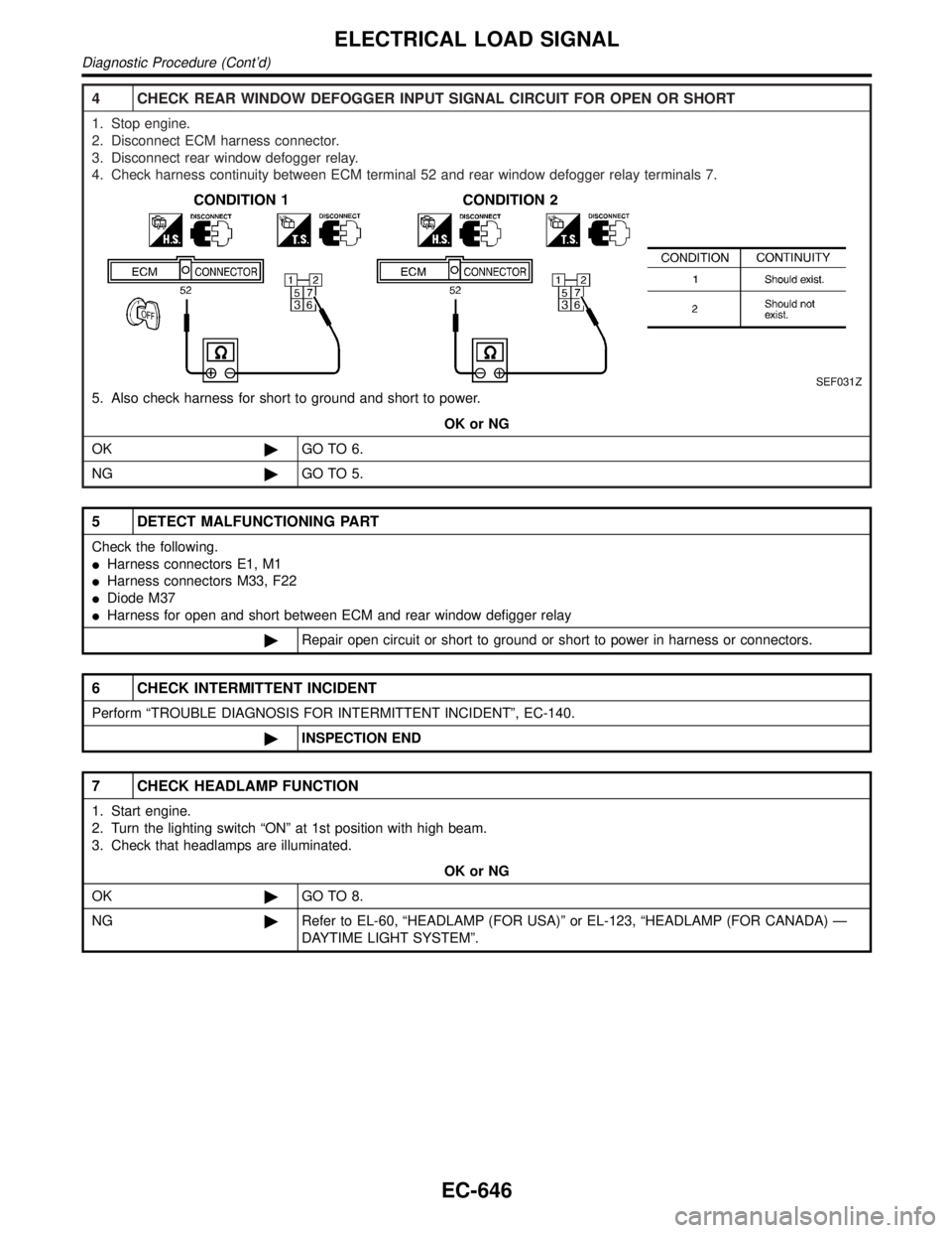
4 CHECK REAR WINDOW DEFOGGER INPUT SIGNAL CIRCUIT FOR OPEN OR SHORT
1. Stop engine.
2. Disconnect ECM harness connector.
3. Disconnect rear window defogger relay.
4. Check harness continuity between ECM terminal 52 and rear window defogger relay terminals 7.
SEF031Z
5. Also check harness for short to ground and short to power.
OK or NG
OK©GO TO 6.
NG©GO TO 5.
5 DETECT MALFUNCTIONING PART
Check the following.
IHarness connectors E1, M1
IHarness connectors M33, F22
IDiode M37
IHarness for open and short between ECM and rear window defigger relay
©Repair open circuit or short to ground or short to power in harness or connectors.
6 CHECK INTERMITTENT INCIDENT
Perform ªTROUBLE DIAGNOSIS FOR INTERMITTENT INCIDENTº, EC-140.
©INSPECTION END
7 CHECK HEADLAMP FUNCTION
1. Start engine.
2. Turn the lighting switch ªONº at 1st position with high beam.
3. Check that headlamps are illuminated.
OK or NG
OK©GO TO 8.
NG©Refer to EL-60, ªHEADLAMP (FOR USA)º or EL-123, ªHEADLAMP (FOR CANADA) Ð
DAYTIME LIGHT SYSTEMº.
ELECTRICAL LOAD SIGNAL
Diagnostic Procedure (Cont'd)
EC-646
Page 1184 of 2395
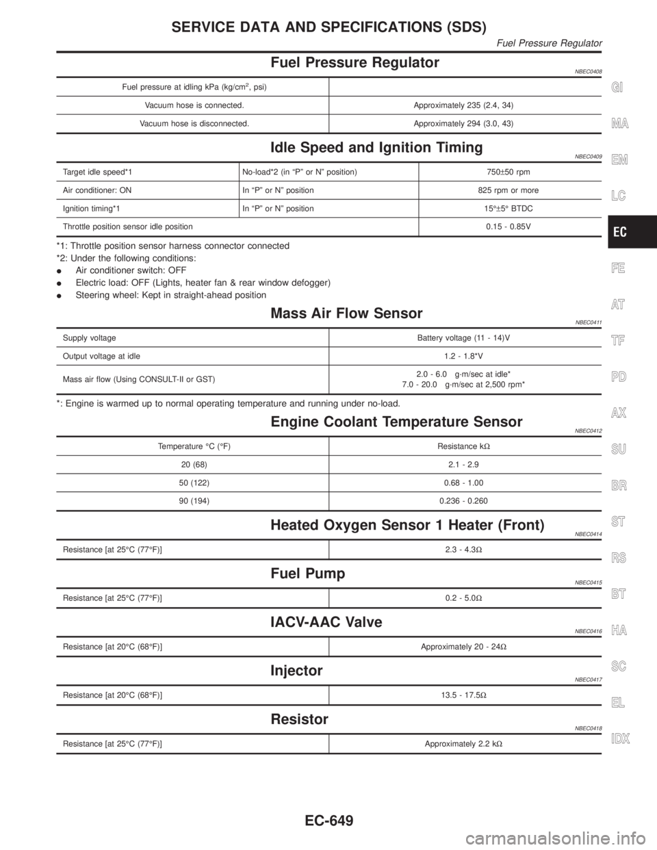
Fuel Pressure RegulatorNBEC0408
Fuel pressure at idling kPa (kg/cm2, psi)
Vacuum hose is connected. Approximately 235 (2.4, 34)
Vacuum hose is disconnected. Approximately 294 (3.0, 43)
Idle Speed and Ignition TimingNBEC0409
Target idle speed*1 No-load*2 (in ªPº or Nº position) 750±50 rpm
Air conditioner: ON In ªPº or Nº position 825 rpm or more
Ignition timing*1 In ªPº or Nº position 15ɱ5É BTDC
Throttle position sensor idle position0.15 - 0.85V
*1: Throttle position sensor harness connector connected
*2: Under the following conditions:
IAir conditioner switch: OFF
IElectric load: OFF (Lights, heater fan & rear window defogger)
ISteering wheel: Kept in straight-ahead position
Mass Air Flow SensorNBEC0411
Supply voltageBattery voltage (11 - 14)V
Output voltage at idle1.2 - 1.8*V
Mass air flow (Using CONSULT-II or GST)2.0 - 6.0 g´m/sec at idle*
7.0 - 20.0 g´m/sec at 2,500 rpm*
*: Engine is warmed up to normal operating temperature and running under no-load.
Engine Coolant Temperature SensorNBEC0412
Temperature ÉC (ÉF) Resistance kW
20 (68) 2.1 - 2.9
50 (122) 0.68 - 1.00
90 (194) 0.236 - 0.260
Heated Oxygen Sensor 1 Heater (Front)NBEC0414
Resistance [at 25ÉC (77ÉF)]2.3 - 4.3W
Fuel PumpNBEC0415
Resistance [at 25ÉC (77ÉF)]0.2 - 5.0W
IACV-AAC ValveNBEC0416
Resistance [at 20ÉC (68ÉF)]Approximately 20 - 24W
InjectorNBEC0417
Resistance [at 20ÉC (68ÉF)]13.5 - 17.5W
ResistorNBEC0418
Resistance [at 25ÉC (77ÉF)]Approximately 2.2 kW
GI
MA
EM
LC
FE
AT
TF
PD
AX
SU
BR
ST
RS
BT
HA
SC
EL
IDX
SERVICE DATA AND SPECIFICATIONS (SDS)
Fuel Pressure Regulator
EC-649
Page 1187 of 2395
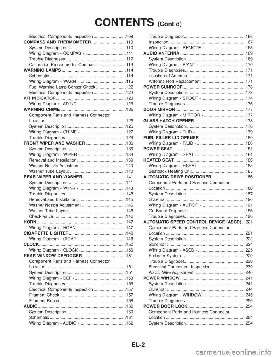
Electrical Components Inspection ...........................108
COMPASS AND THERMOMETER............................. 110
System Description .................................................. 110
Wiring Diagram - COMPAS -................................... 111
Trouble Diagnoses................................................... 112
Calibration Procedure for Compass ........................ 113
WARNING LAMPS...................................................... 114
Schematic ................................................................ 114
Wiring Diagram - WARN - ....................................... 115
Fuel Warning Lamp Sensor Check .........................122
Electrical Components Inspection ...........................122
A/T INDICATOR...........................................................123
Wiring Diagram - AT/IND -.......................................123
WARNING CHIME.......................................................125
Component Parts and Harness Connector
Location ...................................................................125
System Description ..................................................125
Wiring Diagram - CHIME - ......................................127
Trouble Diagnoses...................................................129
FRONT WIPER AND WASHER..................................136
System Description ..................................................136
Wiring Diagram - WIPER - ......................................138
Removal and Installation .........................................139
Washer Nozzle Adjustment .....................................140
Washer Tube Layout ...............................................140
REAR WIPER AND WASHER....................................141
System Description ..................................................141
Wiring Diagram - WIP/R -........................................143
Trouble Diagnoses...................................................145
Removal and Installation .........................................145
Washer Nozzle Adjustment .....................................146
Washer Tube Layout ...............................................146
Check Valve .............................................................146
HORN...........................................................................147
Wiring Diagram - HORN - .......................................147
CIGARETTE LIGHTER................................................148
Wiring Diagram - CIGAR -.......................................148
CLOCK.........................................................................150
Wiring Diagram - CLOCK -......................................150
REAR WINDOW DEFOGGER.....................................151
Component Parts and Harness Connector
Location ...................................................................151
System Description ..................................................151
Wiring Diagram - DEF - ...........................................153
Trouble Diagnoses...................................................155
Electrical Components Inspection ...........................157
Filament Check ........................................................157
Filament Repair .......................................................158
AUDIO..........................................................................160
System Description ..................................................160
Schematic ................................................................161
Wiring Diagram - AUDIO - .......................................162Trouble Diagnoses...................................................166
Inspection.................................................................167
Wiring Diagram - REMOTE -...................................168
AUDIO ANTENNA.......................................................169
System Description ..................................................169
Wiring Diagram - P/ANT - .......................................170
Trouble Diagnoses...................................................171
Location of Antenna .................................................171
Antenna Rod Replacement .....................................171
POWER SUNROOF.....................................................173
System Description ..................................................173
Wiring Diagram - SROOF - .....................................174
Trouble Diagnoses...................................................176
DOOR MIRROR...........................................................177
Wiring Diagram - MIRROR - ...................................177
GLASS HATCH OPENER...........................................178
System Description ..................................................178
Wiring Diagram - TLID - ..........................................179
FUEL FILLER LID OPENER.......................................180
Wiring Diagram - F/LID - .........................................180
POWER SEAT.............................................................181
Wiring Diagram - SEAT - .........................................181
HEATED SEAT............................................................183
Wiring Diagram - HSEAT - ......................................183
Seatback Heating Unit .............................................185
AUTOMATIC DRIVE POSITIONER............................186
Component Parts and Harness Connector
Location ...................................................................186
System Description ..................................................187
Schematic ................................................................190
Wiring Diagram - AUT/DP - .....................................191
On Board Diagnosis ................................................196
Trouble Diagnoses...................................................198
AUTOMATIC SPEED CONTROL DEVICE (ASCD)...221
Component Parts and Harness Connector
Location ...................................................................221
System Description ..................................................222
Schematic ................................................................224
Wiring Diagram - ASCD - ........................................225
Fail-safe System ......................................................229
Trouble Diagnoses...................................................230
Electrical Component Inspection .............................239
ASCD Wire Adjustment ...........................................240
POWER WINDOW.......................................................241
System Description ..................................................241
Schematic ................................................................244
Wiring Diagram - WINDOW - ..................................245
Trouble Diagnoses...................................................250
POWER DOOR LOCK.................................................254
Component Parts and Harness Connector
Location ...................................................................254
System Description ..................................................254
CONTENTS(Cont'd)
EL-2