Page 1265 of 2395

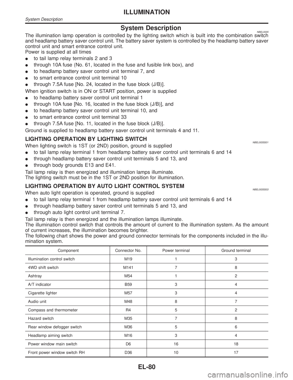
System DescriptionNBEL0035The illumination lamp operation is controlled by the lighting switch which is built into the combination switch
and headlamp battery saver control unit. The battery saver system is controlled by the headlamp battery saver
control unit and smart entrance control unit.
Power is supplied at all times
Ito tail lamp relay terminals 2 and 3
Ithrough 10A fuse (No. 61, located in the fuse and fusible link box), and
Ito headlamp battery saver control unit terminal 7, and
Ito smart entrance control unit terminal 10
Ithrough 7.5A fuse [No. 24, located in the fuse block (J/B)].
When ignition switch is in ON or START position, power is supplied
Ito headlamp battery saver control unit terminal 1
Ithrough 10A fuse [No. 16, located in the fuse block (J/B)], and
Ito headlamp battery saver control unit terminal 10, and
Ito smart entrance control unit terminal 33
Ithrough 7.5A fuse [No. 11, located in the fuse block (J/B)].
Ground is supplied to headlamp battery saver control unit terminals 4 and 11.
LIGHTING OPERATION BY LIGHTING SWITCHNBEL0035S01When lighting switch is 1ST (or 2ND) position, ground is supplied
Ito tail lamp relay terminal 1 from headlamp battery saver control unit terminals 6 and 14
Ithrough headlamp battery saver control unit terminals 5 and 13, and
Ithrough body grounds E13 and E41.
Tail lamp relay is then energized and illumination lamps illuminate.
The lighting switch must be in the 1ST or 2ND position for illumination.
LIGHTING OPERATION BY AUTO LIGHT CONTROL SYSTEMNBEL0035S03When auto light operation is operated, ground is supplied
Ito tail lamp relay terminal 1 from headlamp battery saver control unit terminals 6 and 14
Ithrough headlamp battery saver control unit terminals 5 and 13, and
Ithrough auto light control unit terminal 7.
Tail lamp relay is then energized and the illumination lamps illuminate.
The illumination control switch that controls the amount of current to the illumination system. As the amount
of current increases, the illumination becomes brighter.
The following chart shows the power and ground connector terminals for the components included in the illu-
mination system.
Component Connector No. Power terminal Ground terminal
Illumination control switch M19 1 3
4WD shift switch M141 7 8
Ashtray M54 1 2
A/T indicator B59 3 4
Cigarette lighter M57 3 4
Audio unit M48 8 7
Compass and thermometer R4 5 2
Hazard switch M35 7 8
Rear window defogger switch M36 5 6
Headlamp aiming switch M16 3 4
Power window main switch D6 16 18
Front power window switch RH D36 10 17
ILLUMINATION
System Description
EL-80
Page 1336 of 2395

Component Parts and Harness Connector
Location
NBEL0072
SEL465X
System DescriptionNBEL0073The rear window defogger system is controlled by the smart entrance control unit. The rear window defogger
operates only for approximately 15 minutes.
Power is supplied at all times
Ito rear window defogger relay terminal 3
Ithrough 20A fuse (No. 56, located in the fuse and fusible link box) and
Ito rear window defogger relay terminal 6
Ithrough 20A fuse (No. 57, located in the fuse and fusible link box)
Ito smart entrance control unit terminal 10
Ithrough 7.5A [No. 24, located in fuse block (J/B)]
With the ignition switch in the ON or START position, power is supplied
Ithrough 7.5A fuse [No. 11, located in the fuse block (J/B)]
Ito the rear window defogger relay terminal 1, and
Ito smart entrance control unit terminal 33.
Ground is supplied
Ito terminal 1 of the rear window defogger switch
Ithrough body grounds M4, M66 and M147(with navigation system),
Ito terminal 32 of the A/C auto amp.
Ithrough body grounds M4, M66 and M147 (without navigation system), or
Ito smart entrance control unit terminal 16
Ithrough body grounds M77 and M111.
GI
MA
EM
LC
EC
FE
AT
TF
PD
AX
SU
BR
ST
RS
BT
HA
SC
IDX
REAR WINDOW DEFOGGER
Component Parts and Harness Connector Location
EL-151
Page 1337 of 2395

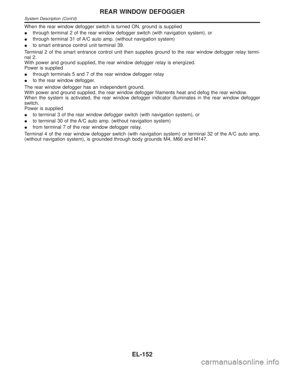
When the rear window defogger switch is turned ON, ground is supplied
Ithrough terminal 2 of the rear window defogger switch (with navigation system), or
Ithrough terminal 31 of A/C auto amp. (without navigation system)
Ito smart entrance control unit terminal 39.
Terminal 2 of the smart entrance control unit then supplies ground to the rear window defogger relay termi-
nal 2.
With power and ground supplied, the rear window defogger relay is energized.
Power is supplied
Ithrough terminals 5 and 7 of the rear window defogger relay
Ito the rear window defogger.
The rear window defogger has an independent ground.
With power and ground supplied, the rear window defogger filaments heat and defog the rear window.
When the system is activated, the rear window defogger indicator illuminates in the rear window defogger
switch.
Power is supplied
Ito terminal 3 of the rear window defogger switch (with navigation system), or
Ito terminal 30 of the A/C auto amp. (without navigation system)
Ifrom terminal 7 of the rear window defogger relay.
Terminal 4 of the rear window defogger switch (with navigation system) or terminal 32 of the A/C auto amp.
(without navigation system), is grounded through body grounds M4, M66 and M147.
REAR WINDOW DEFOGGER
System Description (Cont'd)
EL-152
Page 1338 of 2395
Wiring Diagram Ð DEF ÐNBEL0074
MEL815L
GI
MA
EM
LC
EC
FE
AT
TF
PD
AX
SU
BR
ST
RS
BT
HA
SC
IDX
REAR WINDOW DEFOGGER
Wiring Diagram Ð DEF Ð
EL-153
Page 1339 of 2395
MEL816L
REAR WINDOW DEFOGGER
Wiring Diagram Ð DEF Ð (Cont'd)
EL-154
Page 1340 of 2395

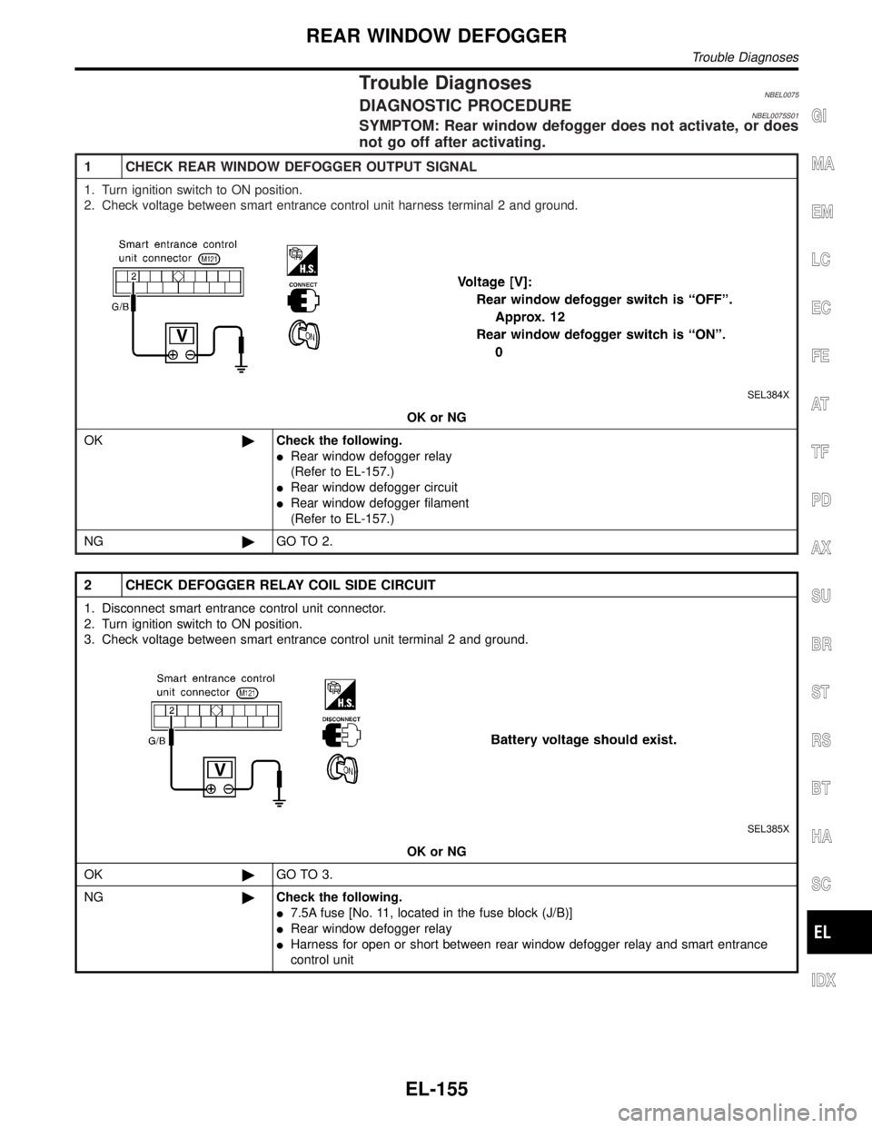
Trouble DiagnosesNBEL0075DIAGNOSTIC PROCEDURENBEL0075S01SYMPTOM: Rear window defogger does not activate, or does
not go off after activating.
1 CHECK REAR WINDOW DEFOGGER OUTPUT SIGNAL
1. Turn ignition switch to ON position.
2. Check voltage between smart entrance control unit harness terminal 2 and ground.
SEL384X
OK or NG
OK©Check the following.
IRear window defogger relay
(Refer to EL-157.)
IRear window defogger circuit
IRear window defogger filament
(Refer to EL-157.)
NG©GO TO 2.
2 CHECK DEFOGGER RELAY COIL SIDE CIRCUIT
1. Disconnect smart entrance control unit connector.
2. Turn ignition switch to ON position.
3. Check voltage between smart entrance control unit terminal 2 and ground.
SEL385X
OK or NG
OK©GO TO 3.
NG©Check the following.
I7.5A fuse [No. 11, located in the fuse block (J/B)]
IRear window defogger relay
IHarness for open or short between rear window defogger relay and smart entrance
control unit
GI
MA
EM
LC
EC
FE
AT
TF
PD
AX
SU
BR
ST
RS
BT
HA
SC
IDX
REAR WINDOW DEFOGGER
Trouble Diagnoses
EL-155
Page 1341 of 2395
3 CHECK REAR WINDOW DEFOGGER SWITCH INPUT SIGNAL
Check continuity between smart entrance control unit terminal 39 and ground.
SEL386X
OK or NG
OK©GO TO 4.
NG©Check the following.
IRear window defogger switch (with navigation system)
(Refer to EL-157.)
IA/C auto amp. (without navigation system)
IHarness for open or short between smart entrance control unit and rear window defog-
ger switch (with navigation system) or A/C auto amp. (without navigation system)
IRear window defogger switch (with navigation system) or A/C auto amp. (without navi-
gation system) ground circuit
4 CHECK IGNITION INPUT SIGNAL
Check voltage between smart entrance control unit terminal 33 and ground.
SEL387X
OK or NG
OK©GO TO 5.
NG©Check the following.
I7.5A fuse [No. 11, located in the fuse block (J/B)]
IHarness for open or short between smart entrance control unit and fuse
REAR WINDOW DEFOGGER
Trouble Diagnoses (Cont'd)
EL-156
Page 1342 of 2395
5 CHECK SMART ENTRANCE CONTROL UNIT GROUND CIRCUIT
Check continuity between smart entrance control unit terminal 16 and ground.
SEL388X
OK or NG
OK©Replace smart entrance control unit.
NG©Repair harness or connectors.
SEC202B
Electrical Components InspectionNBEL0076REAR WINDOW DEFOGGER RELAYNBEL0076S01Check continuity between terminals 3 and 5, 6 and 7.
Condition Continuity
12V direct current supply between ter-
minals 1 and 2Ye s
No current supply No
SEL430TB
REAR WINDOW DEFOGGER SWITCHNBEL0076S02Check continuity between terminals when rear window defogger
switch is pushed and released.
Terminals Condition Continuity
1-2Rear window defogger
switch is pushedYe s
Rear window defogger
switch is releasedNo
SEL263
Filament CheckNBEL00771. Attach probe circuit tester (in volt range) to middle portion of
each filament.
GI
MA
EM
LC
EC
FE
AT
TF
PD
AX
SU
BR
ST
RS
BT
HA
SC
IDX
REAR WINDOW DEFOGGER
Trouble Diagnoses (Cont'd)
EL-157