Page 1073 of 2395
18 CHECK ABSOLUTE PRESSURE SENSOR
1. Remove absolute pressure sensor with its harness connector connected.
SEF961Y
2. Remove hose from absolute pressure sensor.
3. Install a vacuum pump to absolute pressure sensor.
4. Turn ignition switch ªONº and check output voltage between ECM terminal 80 and engine ground under the following
conditions.
SEF300XA
CAUTION:
IAlways calibrate the vacuum pump gauge when using it.
IDo not apply below þ93.3 kPa (±700 mmHg, ±27.56 inHg) or over 101.3 kPa (760 mmHg, 29.92 inHg) of pressure.
OK or NG
OK©GO TO 19.
NG©Replace absolute pressure sensor.
19 CHECK FUEL TANK TEMPERATURE SENSOR
1. Remove fuel level sensor unit.
2. Check resistance between fuel level sensor unit and fuel pump terminals 1 and 2 by heating with hot water or heat gun
as shown in the figure.
SEF974Y
OK or NG
OK©GO TO 20.
NG©Replace fuel level sensor unit.
DTC P1441 EVAP CONTROL SYSTEM (VERY SMALL LEAK)
Diagnostic Procedure (Cont'd)
EC-538
Page 1074 of 2395

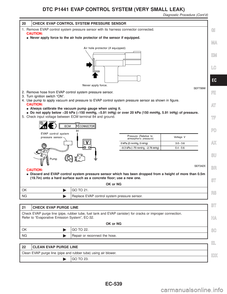
20 CHECK EVAP CONTROL SYSTEM PRESSURE SENSOR
1. Remove EVAP control system pressure sensor with its harness connector connected.
CAUTION:
INever apply force to the air hole protector of the sensor if equipped.
SEF799W
2. Remove hose from EVAP control system pressure sensor.
3. Turn ignition switch ªONº.
4. Use pump to apply vacuum and pressure to EVAP control system pressure sensor as shown in figure.
CAUTION:
IAlways calibrate the vacuum pump gauge when using it.
IDo not apply below þ20 kPa (þ150 mmHg, þ5.91 inHg) or over 20 kPa (150 mmHg, 5.91 inHg) of pressure.
5. Check input voltage between ECM terminal 84 and ground.
SEF342X
CAUTION:
IDiscard and EVAP control system pressure sensor which has been dropped from a height of more than 0.5m
(19.7in) onto a hard surface such as a concrete floor; use a new one.
OK or NG
OK©GO TO 21.
NG©Replace EVAP control system pressure sensor.
21 CHECK EVAP PURGE LINE
Check EVAP purge line (pipe, rubber tube, fuel tank and EVAP canister) for cracks or improper connection.
Refer to ªEvaporative Emission Systemº, EC-32.
OK or NG
OK©GO TO 22.
NG©Repair or reconnect the hose.
22 CLEAN EVAP PURGE LINE
Clean EVAP purge line (pipe and rubber tube) using air blower.
©GO TO 23.
GI
MA
EM
LC
FE
AT
TF
PD
AX
SU
BR
ST
RS
BT
HA
SC
EL
IDX
DTC P1441 EVAP CONTROL SYSTEM (VERY SMALL LEAK)
Diagnostic Procedure (Cont'd)
EC-539
Page 1160 of 2395

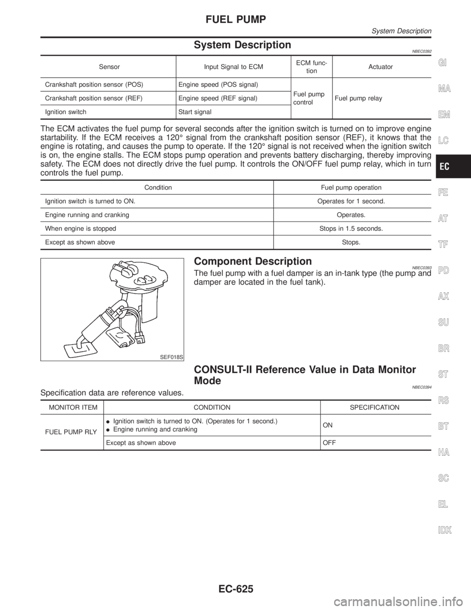
System DescriptionNBEC0392
Sensor Input Signal to ECMECM func-
tionActuator
Crankshaft position sensor (POS) Engine speed (POS signal)
Fuel pump
controlFuel pump relay Crankshaft position sensor (REF) Engine speed (REF signal)
Ignition switch Start signal
The ECM activates the fuel pump for several seconds after the ignition switch is turned on to improve engine
startability. If the ECM receives a 120É signal from the crankshaft position sensor (REF), it knows that the
engine is rotating, and causes the pump to operate. If the 120É signal is not received when the ignition switch
is on, the engine stalls. The ECM stops pump operation and prevents battery discharging, thereby improving
safety. The ECM does not directly drive the fuel pump. It controls the ON/OFF fuel pump relay, which in turn
controls the fuel pump.
Condition Fuel pump operation
Ignition switch is turned to ON. Operates for 1 second.
Engine running and cranking Operates.
When engine is stopped Stops in 1.5 seconds.
Except as shown aboveStops.
SEF018S
Component DescriptionNBEC0393The fuel pump with a fuel damper is an in-tank type (the pump and
damper are located in the fuel tank).
CONSULT-II Reference Value in Data Monitor
Mode
NBEC0394Specification data are reference values.
MONITOR ITEM CONDITION SPECIFICATION
FUEL PUMP RLYIIgnition switch is turned to ON. (Operates for 1 second.)
IEngine running and crankingON
Except as shown above OFF
GI
MA
EM
LC
FE
AT
TF
PD
AX
SU
BR
ST
RS
BT
HA
SC
EL
IDX
FUEL PUMP
System Description
EC-625
Page 1161 of 2395
ECM Terminals and Reference Value=NBEC0686Specification data are reference values and are measured between each terminal and ground.
CAUTION:
Do not use ECM ground terminals when measuring input/output voltage. Doing so may result in dam-
age to the ECM's transistor. Use a ground other than ECM terminals, such as the ground.
TERMI-
NAL
NO.WIRE
COLORITEM CONDITION DATA (DC Voltage)
28 R/L Fuel pump relay[Ignition switch ªONº]
IFor 1 second after turning ignition switch ªONº
[Engine is running]0 - 1.5V
[Ignition switch ªONº]
I1 second passed after turning ignition switch
ªONº.BATTERY VOLTAGE
(11 - 14V)
FUEL PUMP
ECM Terminals and Reference Value
EC-626
Page 1162 of 2395
Wiring DiagramNBEC0396
MEC976C
GI
MA
EM
LC
FE
AT
TF
PD
AX
SU
BR
ST
RS
BT
HA
SC
EL
IDX
FUEL PUMP
Wiring Diagram
EC-627
Page 1163 of 2395
Diagnostic ProcedureNBEC0397
1 CHECK OVERALL FUNCTION
1. Turn ignition switch ªONº.
2. Pinch fuel feed hose with two fingers.
SEF025Z
Fuel pressure pulsation should be felt on the fuel feed hose for 1 second after ignition switch is turned ªONº.
OK or NG
OK©INSPECTION END
NG©GO TO 2.
2 CHECK FUEL PUMP RELAY-1 and -2 POWER SUPPLY CIRCUIT-I
1. Turn ignition switch ªOFFº.
2. Disconnect fuel pump relay-1 and -2.
SEF346Z
3. Turn ignition switch ªONº.
4. Check voltage between terminals 2 and ground with CONSULT-II or tester.
SEF347Z
OK or NG
OK©GO TO 4.
NG©GO TO 3.
FUEL PUMP
Diagnostic Procedure
EC-628
Page 1164 of 2395
3 DETECT MALFUNCTIONING PART
Check the following.
IFuse block (J/B) connector M10
I15A fuse in fuse block (J/B)
IHarness connectors M1, E1
IHarness for open or short between fuse and fuel pump relay-1 and fuel pump relay-2
©Repair harness or connectors.
4 CHECK FUEL PUMP RELAY-1 POWER SUPPLY CIRCUIT-II
Check voltage between terminal 3 and ground with CONSULT-II or tester.
SEF348Z
OK or NG
OK©GO TO 8.
NG©GO TO 5.
5 CHECK FUEL PUMP RELAY-2 OUTPUT SIGNAL CIRCUIT FOR OPEN AND SHORT
1. Disconnect fuel pump relay-2.
2. Check harness continuity between fuel pump relay-2 terminal 5 and fuel pump relay-1 terminal 3. Refer to Wiring Dia-
gram.
Continuity should exist.
3. Also check harness for short to ground and short to power.
OK or NG
OK©GO TO 6.
NG©Repair open circuit or short to ground or short to power in harness or connectors.
GI
MA
EM
LC
FE
AT
TF
PD
AX
SU
BR
ST
RS
BT
HA
SC
EL
IDX
FUEL PUMP
Diagnostic Procedure (Cont'd)
EC-629
Page 1165 of 2395
6 CHECK FUEL PUMP RELAY POWER SUPPLY CIRCUIT-III
1. Turn ignition switch ªOFFº.
2. Disconnect fuel pump relay-2.
3. Turn ignition switch ªONº.
4. Check voltage between terminals 2, 3 and ground with CONSULT-II or tester.
SEF026Z
OK or NG
OK©GO TO 8.
NG©GO TO 7.
7 DETECT MALFUNCTIONING PART
Check the following.
I15A fuse in fusible link and relay box
IHarness for open or short between fuse and fuel pump relay-2
©Repair harness or connectors.
8 CHECK FUEL PUMP RELAY-2 GROUND CIRCUIT FOR OPEN AND SHORT
1. Check harness continuity between fuel pump relay-2 terminal 1 and ground.
Continuity should exist.
2. Also check harness for short to power.
OK or NG
©Repair open circuit or short to power in harness or connector.
FUEL PUMP
Diagnostic Procedure (Cont'd)
EC-630