2001 INFINITI QX4 fuel pump
[x] Cancel search: fuel pumpPage 1735 of 2395
SFE422A
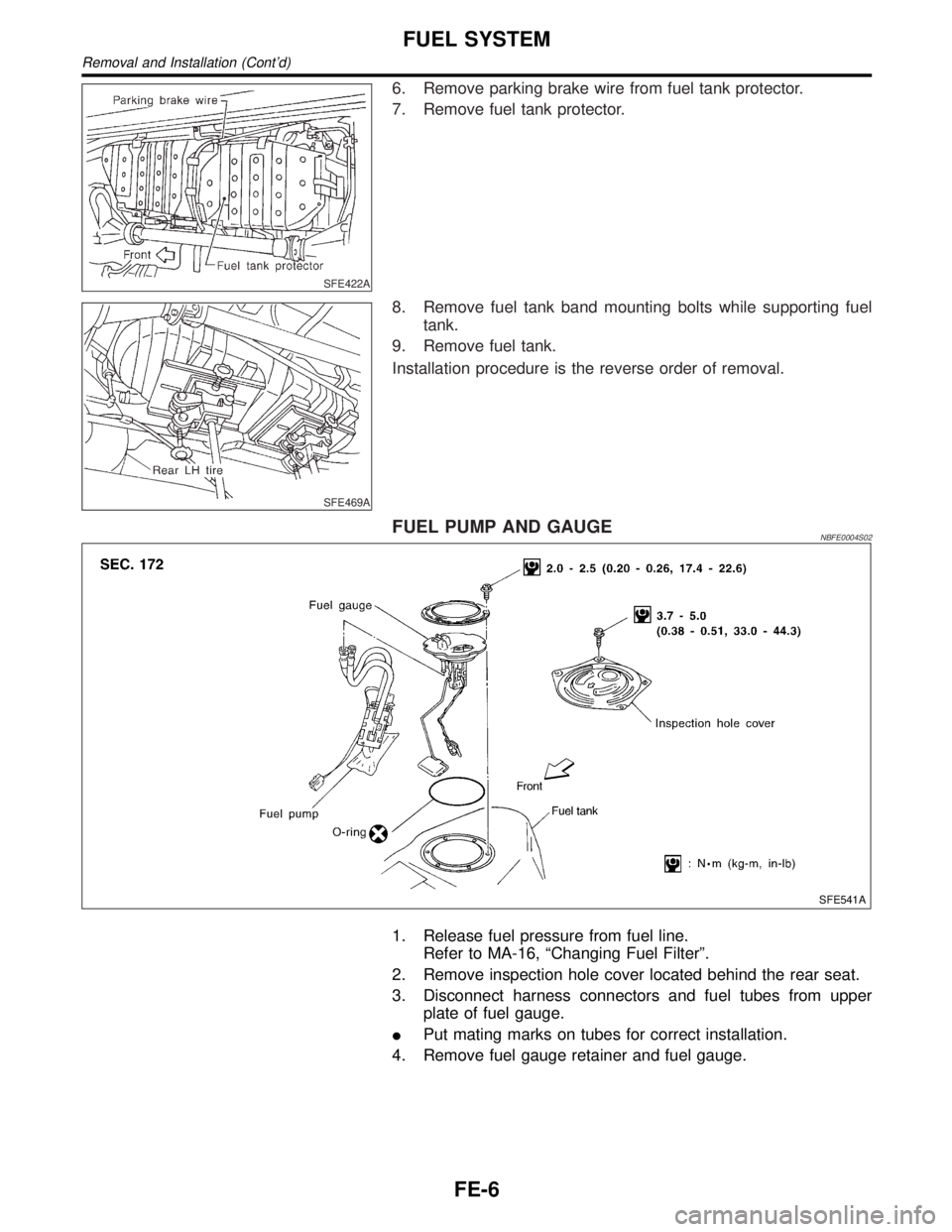
6. Remove parking brake wire from fuel tank protector.
7. Remove fuel tank protector.
SFE469A
8. Remove fuel tank band mounting bolts while supporting fuel
tank.
9. Remove fuel tank.
Installation procedure is the reverse order of removal.
FUEL PUMP AND GAUGENBFE0004S02
SFE541A
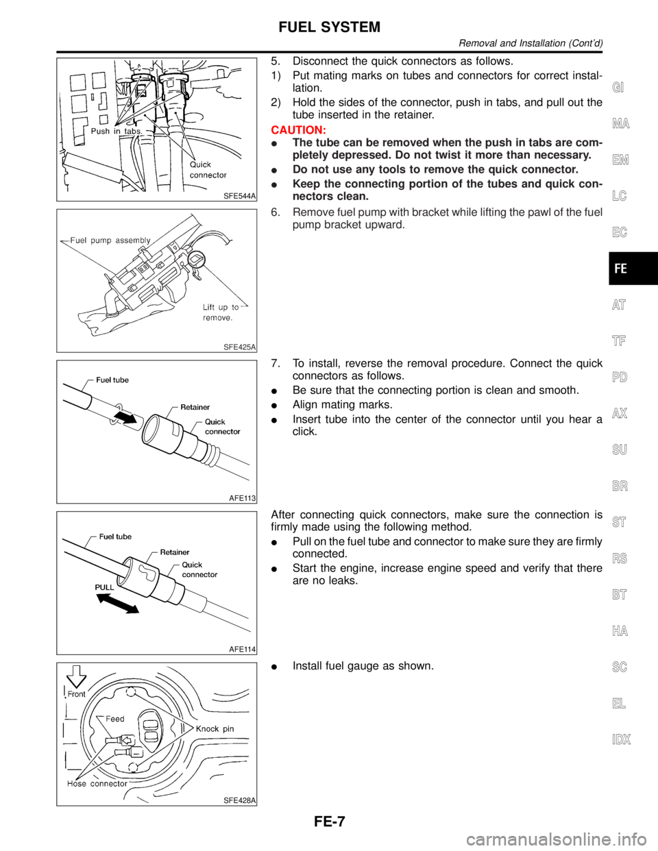
1. Release fuel pressure from fuel line.
Refer to MA-16, ªChanging Fuel Filterº.
2. Remove inspection hole cover located behind the rear seat.
3. Disconnect harness connectors and fuel tubes from upper
plate of fuel gauge.
IPut mating marks on tubes for correct installation.
4. Remove fuel gauge retainer and fuel gauge.
FUEL SYSTEM
Removal and Installation (Cont'd)
FE-6
Page 1736 of 2395
SFE544A
5. Disconnect the quick connectors as follows.
1) Put mating marks on tubes and connectors for correct instal-
lation.
2) Hold the sides of the connector, push in tabs, and pull out the
tube inserted in the retainer.
CAUTION:
IThe tube can be removed when the push in tabs are com-
pletely depressed. Do not twist it more than necessary.
IDo not use any tools to remove the quick connector.
IKeep the connecting portion of the tubes and quick con-
nectors clean.
SFE425A
6. Remove fuel pump with bracket while lifting the pawl of the fuel
pump bracket upward.
AFE113
7. To install, reverse the removal procedure. Connect the quick
connectors as follows.
IBe sure that the connecting portion is clean and smooth.
IAlign mating marks.
IInsert tube into the center of the connector until you hear a
click.
AFE114
After connecting quick connectors, make sure the connection is
firmly made using the following method.
IPull on the fuel tube and connector to make sure they are firmly
connected.
IStart the engine, increase engine speed and verify that there
are no leaks.
SFE428A
IInstall fuel gauge as shown.
GI
MA
EM
LC
EC
AT
TF
PD
AX
SU
BR
ST
RS
BT
HA
SC
EL
IDX
FUEL SYSTEM
Removal and Installation (Cont'd)
FE-7
Page 1745 of 2395
QUICK REFERENCE CHART: QX42001
Engine model VQ35DE
Firing order 1-2-3-4-5-6
Idle speed rpmA/T
(in ªNº position)750 50
Ignition timing (degree BTDC at idle speed) 15É 2É
CO% at idleIdle mixture screw is preset and
sealed at factory.
Drive belt deflection (Cold) mm (in) Used belt
Deflection of
new belt
LimitDeflection
after
adjustment
Alternator
Power steering oil pump
Fan7 (0.28)4-5
(0.16 - 0.20)3.5 - 4.5
(0.138 - 0.177)
Air conditioner compressor 12 (0.472)9-10
(0.354 - 0.394)8-9
(0.31 - 0.35)
Applied pressed force
N (kg, lb)98 (10, 22)
Drive belt tension adjustment (Cold)
N (kg, lb)Used belt
New belt
LimitAfter
adjustment
Alternator
Power steering pump
Fan294 (30, 66)730 - 818
(74.4 - 83.5,
164 - 184)838 - 926
(85.4 - 94.5,
188 - 208)
Air conditioner compressor 196 (20, 44)348 - 436
(35.5 - 44.5,
78 - 98)470 - 559
(47.9 - 57.0,
106 - 126)
Radiator cap relief pressure
kPa (kg/cm
2, psi)78 - 98 (0.8 - 1.0, 11 - 14)
Cooling system leakage testing pressure
kPa (kg/cm
2, psi)157 (1.6, 23)
Compression pressure
kPa (kg/cm
2, psi)/rpmStandard 1,275 (13.0, 185)/300
Minimum 981 (10.0, 142)/300
Spark plugStandard PLFR5A-11
Cold PLFR6A-11
Hot PLFR4A-11
Applied model 245/70 R16 tire
Camber
Degree minute
(Decimal degree)Minimum þ0É35¢(þ0.58É)
Nominal 0É10¢(0.17É)
Maximum 0É55¢(0.92É)
Left and right
difference45¢(0.75É) or less
Caster
Degree minute
(Decimal degree)Minimum 2É15¢(2.25É)
Nominal 3É00¢(3.00É)
Maximum 3É45¢(3.75É)
Left and right
difference45¢(0.75É) or less
Total toe-in Minimum 1 (0.04)
Distance (A þ B)
mm (in)Nominal 2 (0.08)
Maximum 3 (0.12)
Angle (left plus right)
Degree minute
(Decimal degree)Minimum 5¢(0.08É)
Nominal 10¢(0.17É)
Maximum 15¢(0.25É)
Wheel turning angle
(Full turn)Minimum 30É00¢(30.00É)
Inside
Degree minute
(Decimal degree)Nominal 33É00¢(33.00É)
Maximum 34É00¢(34.00É)
Outside
Degree minute
(Decimal degree)Minimum 28É00¢(28.00É)
Nominal 31É00¢(31.00É)
Maximum 32É00¢(32.00É)
* Fuel, radiator coolant and engine oil full.
Spare tire, jack, hand tools and mats in designated positions.
Unit: mm (in)Front brake
Pad wear limit 2.0 (0.079)
Rotor repair limit 26.0 (1.024)
Rear brake
Lining wear limit 1.5 (0.059)
Drum repair limit 296.5 (11.67)
Pedal free height 175 - 185 (6.89 - 7.28)
Pedal depressed height*1 70 (2.76)
Parking brake
Number of notches*2 6 - 8
*1 Under force of 490 N (50 kg, 110 lb) with engine running
*2 At pulling force: 196 N (20 kg, 44 lb)
Unit Liter US measure
Coolant with reservoir 9.2 9-3/4 qt
Engine*With oil filter 5.0 5-1/4 qt
Without oil filter 4.8 5-1/8 qt
Dry engine (engine overhaul) 6.8 7-1/4 qt
Transmis-
sionA/T2WD
8.5 9 qt
4WD
All-mode 4WD transfer 3.0 2-5/8 qt
Differential carrierFront 1.85 3-7/8 pt
Rear 2.8 5-7/8 pt
Power steering system 0.9 1 qt
Air conditioning systemRefrigerant 0.60 - 0.70 kg 1.32 - 1.54 lb
Compressor
oil0.20 6.8 fl oz
* For further details, see ªChanging Engine Oilº in MA section.
Preload
(At hub bolt)
N (kg, lb)Wheel bearing lock nut
78-98(8-10,58-72)
Tightening torque
N×m (kg-m, ft-lb)
Retightening torque after loosen-
ing wheel bearing lock nut
N×m (kg-m, in-lb)0.5 - 1.5 (0.05 - 0.15, 4.3 - 13.0)
Axial end play
mm (in)0 (0)
Starting force at wheel hub bolt
N (kg, lb)A
Turning angle
degree15É - 30É
Starting force at wheel hub bolt
N (kg, lb)B
Wheel bearing preload at wheel hub
bolt
B þ A N (kg, lb)7.06 - 20.99 (0.72 - 2.14, 1.59 - 4.72)
Page 1751 of 2395
IClean all disassembled parts in the designated liquid or solvent
prior to inspection or assembly.
IReplace oil seals, gaskets, packings, O-rings, locking washers,
cotter pins, self-locking nuts, etc. with new ones.
IReplace inner and outer races of tapered roller bearings and
needle bearings as a set.
IArrange the disassembled parts in accordance with their
assembled locations and sequence.
IDo not touch the terminals of electrical components which use
microcomputers (such as ECMs).
Static electricity may damage internal electronic components.
IAfter disconnecting vacuum or air hoses, attach a tag to indi-
cate the proper connection.
IUse only the fluids and lubricants specified in this manual.
IUse approved bonding agent, sealants or their equivalents
when required.
IUse tools and recommended special tools where specified for
safe and efficient service repairs.
IWhen repairing the fuel, oil, water, vacuum or exhaust
systems, check all affected lines for leaks.
IDispose of drained oil or the solvent used for cleaning parts in
an appropriate manner.
WARNING:
To prevent ECM from storing the diagnostic trouble codes, do
not carelessly disconnect the harness connectors which are
related to the engine control system and TCM (Transmission
Control Module) system. The connectors should be discon-
nected only when working according to the WORK FLOW of
TROUBLE DIAGNOSES in EC and AT sections.
SGI787
PRECAUTIONS FOR MULTIPORT FUEL INJECTION
SYSTEM OR ENGINE CONTROL SYSTEM
NBGI0001S03IBefore connecting or disconnecting any harness connector for
the multiport fuel injection system or ECM (Engine Control
Module):
Turn ignition switch to OFF position.
Disconnect negative battery terminal.
Otherwise, there may be damage to ECM.
IBefore disconnecting pressurized fuel line from fuel pump to
injectors, be sure to release fuel pressure.
IBe careful not to jar components such as ECM and mass air
flow sensor.
PRECAUTIONS FOR THREE WAY CATALYSTNBGI0001S04If a large amount of unburned fuel flows into the catalyst, the cata-
lyst temperature will be excessively high. To prevent this, follow the
instructions below:
IUse unleaded gasoline only. Leaded gasoline will seriously
damage the three way catalyst.
IWhen checking for ignition spark or measuring engine
compression, make tests quickly and only when necessary.
IDo not run engine when the fuel tank level is low, otherwise the
engine may misfire causing damage to the catalyst.
PRECAUTIONS
Precautions (Cont'd)
GI-6
Page 1798 of 2395
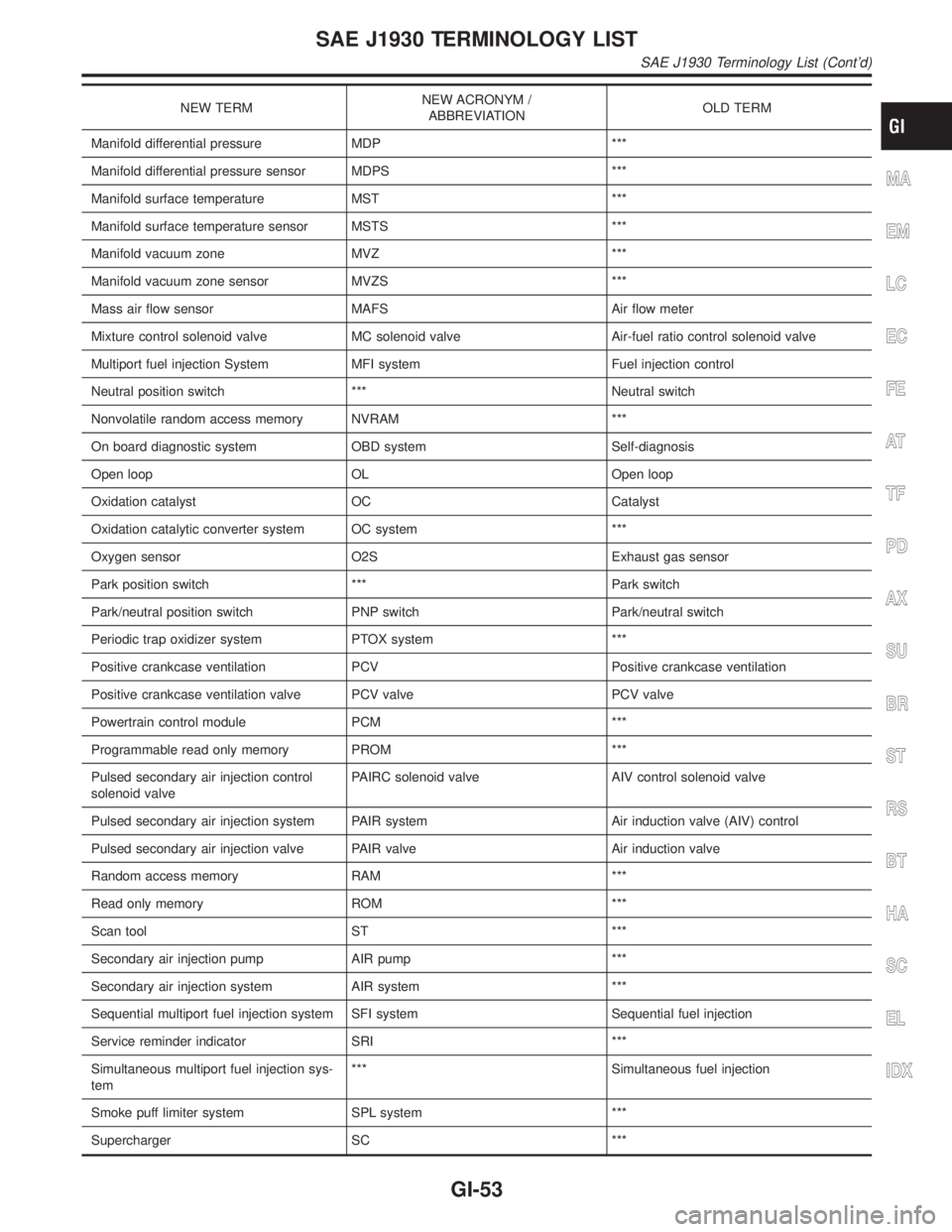
NEW TERMNEW ACRONYM /
ABBREVIATIONOLD TERM
Manifold differential pressure MDP ***
Manifold differential pressure sensor MDPS ***
Manifold surface temperature MST ***
Manifold surface temperature sensor MSTS ***
Manifold vacuum zone MVZ ***
Manifold vacuum zone sensor MVZS ***
Mass air flow sensor MAFS Air flow meter
Mixture control solenoid valve MC solenoid valve Air-fuel ratio control solenoid valve
Multiport fuel injection System MFI system Fuel injection control
Neutral position switch *** Neutral switch
Nonvolatile random access memory NVRAM ***
On board diagnostic system OBD system Self-diagnosis
Open loop OL Open loop
Oxidation catalyst OC Catalyst
Oxidation catalytic converter system OC system ***
Oxygen sensor O2S Exhaust gas sensor
Park position switch *** Park switch
Park/neutral position switch PNP switch Park/neutral switch
Periodic trap oxidizer system PTOX system ***
Positive crankcase ventilation PCV Positive crankcase ventilation
Positive crankcase ventilation valve PCV valve PCV valve
Powertrain control module PCM ***
Programmable read only memory PROM ***
Pulsed secondary air injection control
solenoid valvePAIRC solenoid valve AIV control solenoid valve
Pulsed secondary air injection system PAIR system Air induction valve (AIV) control
Pulsed secondary air injection valve PAIR valve Air induction valve
Random access memory RAM ***
Read only memory ROM ***
Scan tool ST ***
Secondary air injection pump AIR pump ***
Secondary air injection system AIR system ***
Sequential multiport fuel injection system SFI system Sequential fuel injection
Service reminder indicator SRI ***
Simultaneous multiport fuel injection sys-
tem*** Simultaneous fuel injection
Smoke puff limiter system SPL system ***
Supercharger SC ***
MA
EM
LC
EC
FE
AT
TF
PD
AX
SU
BR
ST
RS
BT
HA
SC
EL
IDX
SAE J1930 TERMINOLOGY LIST
SAE J1930 Terminology List (Cont'd)
GI-53
Page 1963 of 2395
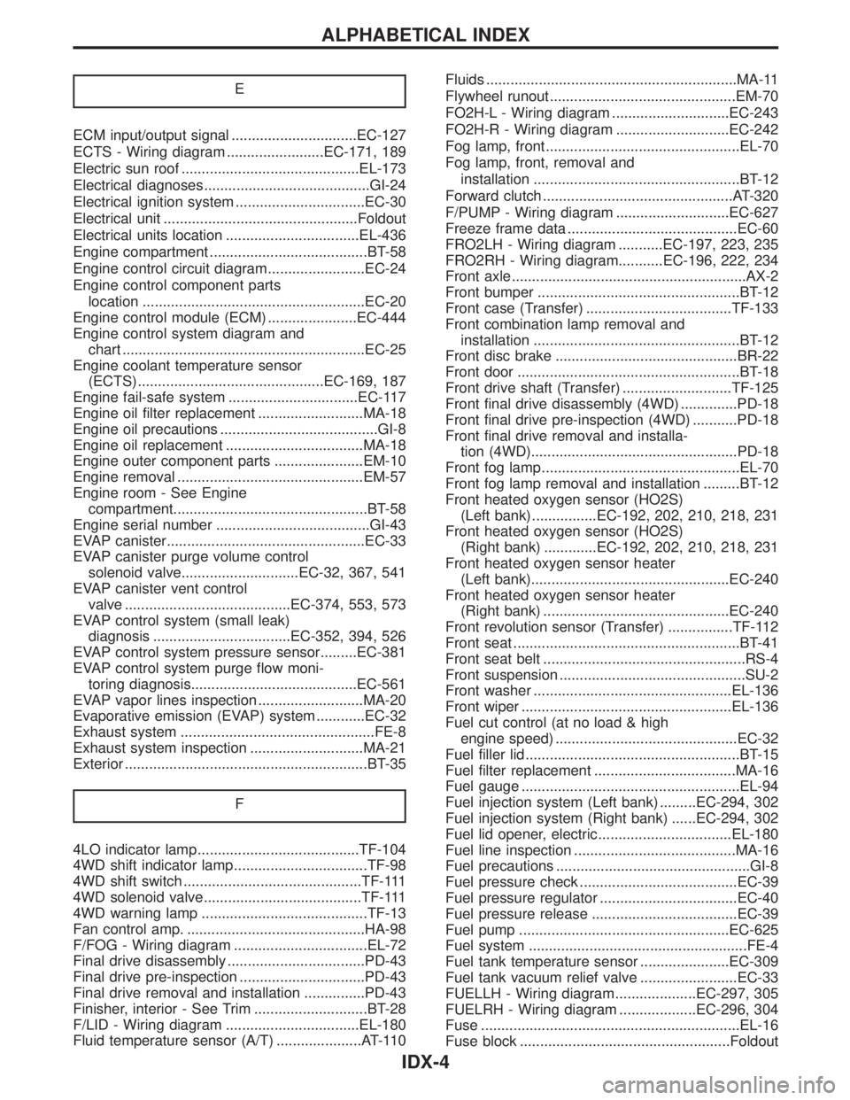
E
ECM input/output signal ...............................EC-127
ECTS - Wiring diagram ........................EC-171, 189
Electric sun roof ............................................EL-173
Electrical diagnoses.........................................GI-24
Electrical ignition system ................................EC-30
Electrical unit ................................................Foldout
Electrical units location .................................EL-436
Engine compartment .......................................BT-58
Engine control circuit diagram........................EC-24
Engine control component parts
location .......................................................EC-20
Engine control module (ECM) ......................EC-444
Engine control system diagram and
chart ............................................................EC-25
Engine coolant temperature sensor
(ECTS) ..............................................EC-169, 187
Engine fail-safe system ................................EC-117
Engine oil filter replacement ..........................MA-18
Engine oil precautions .......................................GI-8
Engine oil replacement ..................................MA-18
Engine outer component parts ......................EM-10
Engine removal ..............................................EM-57
Engine room - See Engine
compartment................................................BT-58
Engine serial number ......................................GI-43
EVAP canister.................................................EC-33
EVAP canister purge volume control
solenoid valve.............................EC-32, 367, 541
EVAP canister vent control
valve .........................................EC-374, 553, 573
EVAP control system (small leak)
diagnosis ..................................EC-352, 394, 526
EVAP control system pressure sensor.........EC-381
EVAP control system purge flow moni-
toring diagnosis.........................................EC-561
EVAP vapor lines inspection ..........................MA-20
Evaporative emission (EVAP) system ............EC-32
Exhaust system ................................................FE-8
Exhaust system inspection ............................MA-21
Exterior ............................................................BT-35
F
4LO indicator lamp........................................TF-104
4WD shift indicator lamp.................................TF-98
4WD shift switch ............................................TF-111
4WD solenoid valve.......................................TF-111
4WD warning lamp .........................................TF-13
Fan control amp. ............................................HA-98
F/FOG - Wiring diagram .................................EL-72
Final drive disassembly ..................................PD-43
Final drive pre-inspection ...............................PD-43
Final drive removal and installation ...............PD-43
Finisher, interior - See Trim ............................BT-28
F/LID - Wiring diagram .................................EL-180
Fluid temperature sensor (A/T) .....................AT-110Fluids ..............................................................MA-11
Flywheel runout..............................................EM-70
FO2H-L - Wiring diagram .............................EC-243
FO2H-R - Wiring diagram ............................EC-242
Fog lamp, front................................................EL-70
Fog lamp, front, removal and
installation ...................................................BT-12
Forward clutch ...............................................AT-320
F/PUMP - Wiring diagram ............................EC-627
Freeze frame data ..........................................EC-60
FRO2LH - Wiring diagram ...........EC-197, 223, 235
FRO2RH - Wiring diagram...........EC-196, 222, 234
Front axle..........................................................AX-2
Front bumper ..................................................BT-12
Front case (Transfer) ....................................TF-133
Front combination lamp removal and
installation ...................................................BT-12
Front disc brake .............................................BR-22
Front door .......................................................BT-18
Front drive shaft (Transfer) ...........................TF-125
Front final drive disassembly (4WD) ..............PD-18
Front final drive pre-inspection (4WD) ...........PD-18
Front final drive removal and installa-
tion (4WD)...................................................PD-18
Front fog lamp.................................................EL-70
Front fog lamp removal and installation .........BT-12
Front heated oxygen sensor (HO2S)
(Left bank) ................EC-192, 202, 210, 218, 231
Front heated oxygen sensor (HO2S)
(Right bank) .............EC-192, 202, 210, 218, 231
Front heated oxygen sensor heater
(Left bank).................................................EC-240
Front heated oxygen sensor heater
(Right bank) ..............................................EC-240
Front revolution sensor (Transfer) ................TF-112
Front seat ........................................................BT-41
Front seat belt ..................................................RS-4
Front suspension ..............................................SU-2
Front washer .................................................EL-136
Front wiper ....................................................EL-136
Fuel cut control (at no load & high
engine speed) .............................................EC-32
Fuel filler lid.....................................................BT-15
Fuel filter replacement ...................................MA-16
Fuel gauge ......................................................EL-94
Fuel injection system (Left bank) .........EC-294, 302
Fuel injection system (Right bank) ......EC-294, 302
Fuel lid opener, electric.................................EL-180
Fuel line inspection ........................................MA-16
Fuel precautions ................................................GI-8
Fuel pressure check .......................................EC-39
Fuel pressure regulator ..................................EC-40
Fuel pressure release ....................................EC-39
Fuel pump ....................................................EC-625
Fuel system ......................................................FE-4
Fuel tank temperature sensor ......................EC-309
Fuel tank vacuum relief valve ........................EC-33
FUELLH - Wiring diagram....................EC-297, 305
FUELRH - Wiring diagram ...................EC-296, 304
Fuse ................................................................EL-16
Fuse block ....................................................Foldout
ALPHABETICAL INDEX
IDX-4
Page 1965 of 2395
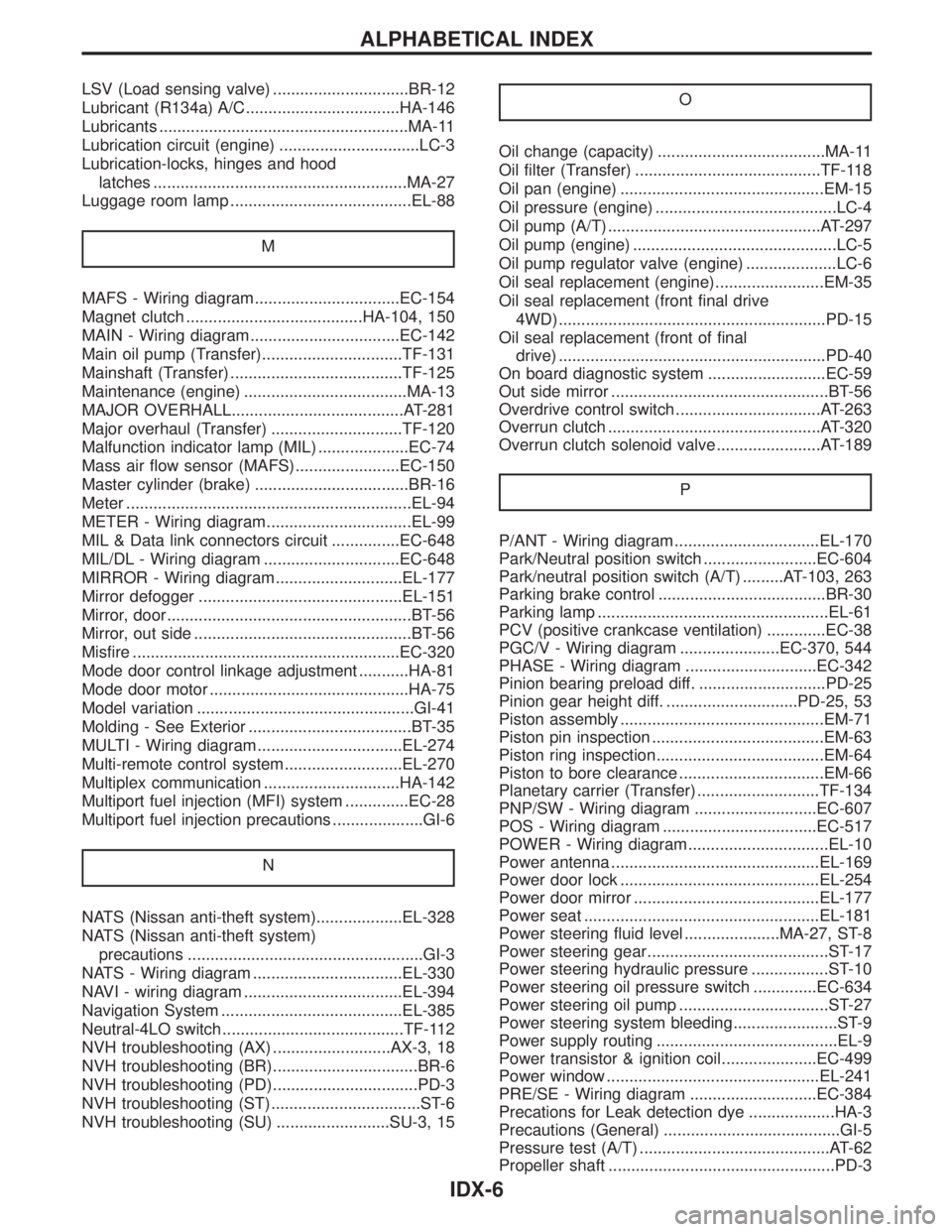
LSV (Load sensing valve) ..............................BR-12
Lubricant (R134a) A/C..................................HA-146
Lubricants .......................................................MA-11
Lubrication circuit (engine) ...............................LC-3
Lubrication-locks, hinges and hood
latches ........................................................MA-27
Luggage room lamp ........................................EL-88
M
MAFS - Wiring diagram................................EC-154
Magnet clutch .......................................HA-104, 150
MAIN - Wiring diagram.................................EC-142
Main oil pump (Transfer)...............................TF-131
Mainshaft (Transfer) ......................................TF-125
Maintenance (engine) ....................................MA-13
MAJOR OVERHALL......................................AT-281
Major overhaul (Transfer) .............................TF-120
Malfunction indicator lamp (MIL) ....................EC-74
Mass air flow sensor (MAFS) .......................EC-150
Master cylinder (brake) ..................................BR-16
Meter ...............................................................EL-94
METER - Wiring diagram................................EL-99
MIL & Data link connectors circuit ...............EC-648
MIL/DL - Wiring diagram ..............................EC-648
MIRROR - Wiring diagram............................EL-177
Mirror defogger .............................................EL-151
Mirror, door......................................................BT-56
Mirror, out side ................................................BT-56
Misfire ...........................................................EC-320
Mode door control linkage adjustment ...........HA-81
Mode door motor ............................................HA-75
Model variation ................................................GI-41
Molding - See Exterior ....................................BT-35
MULTI - Wiring diagram ................................EL-274
Multi-remote control system..........................EL-270
Multiplex communication ..............................HA-142
Multiport fuel injection (MFI) system ..............EC-28
Multiport fuel injection precautions ....................GI-6
N
NATS (Nissan anti-theft system)...................EL-328
NATS (Nissan anti-theft system)
precautions ....................................................GI-3
NATS - Wiring diagram .................................EL-330
NAVI - wiring diagram ...................................EL-394
Navigation System ........................................EL-385
Neutral-4LO switch ........................................TF-112
NVH troubleshooting (AX) ..........................AX-3, 18
NVH troubleshooting (BR)................................BR-6
NVH troubleshooting (PD)................................PD-3
NVH troubleshooting (ST).................................ST-6
NVH troubleshooting (SU) .........................SU-3, 15O
Oil change (capacity) .....................................MA-11
Oil filter (Transfer) .........................................TF-118
Oil pan (engine) .............................................EM-15
Oil pressure (engine) ........................................LC-4
Oil pump (A/T) ...............................................AT-297
Oil pump (engine) .............................................LC-5
Oil pump regulator valve (engine) ....................LC-6
Oil seal replacement (engine)........................EM-35
Oil seal replacement (front final drive
4WD) ...........................................................PD-15
Oil seal replacement (front of final
drive) ...........................................................PD-40
On board diagnostic system ..........................EC-59
Out side mirror ................................................BT-56
Overdrive control switch ................................AT-263
Overrun clutch ...............................................AT-320
Overrun clutch solenoid valve .......................AT-189
P
P/ANT - Wiring diagram ................................EL-170
Park/Neutral position switch .........................EC-604
Park/neutral position switch (A/T) .........AT-103, 263
Parking brake control .....................................BR-30
Parking lamp ...................................................EL-61
PCV (positive crankcase ventilation) .............EC-38
PGC/V - Wiring diagram ......................EC-370, 544
PHASE - Wiring diagram .............................EC-342
Pinion bearing preload diff. ............................PD-25
Pinion gear height diff. .............................PD-25, 53
Piston assembly .............................................EM-71
Piston pin inspection ......................................EM-63
Piston ring inspection.....................................EM-64
Piston to bore clearance ................................EM-66
Planetary carrier (Transfer) ...........................TF-134
PNP/SW - Wiring diagram ...........................EC-607
POS - Wiring diagram ..................................EC-517
POWER - Wiring diagram...............................EL-10
Power antenna ..............................................EL-169
Power door lock ............................................EL-254
Power door mirror .........................................EL-177
Power seat ....................................................EL-181
Power steering fluid level .....................MA-27, ST-8
Power steering gear........................................ST-17
Power steering hydraulic pressure .................ST-10
Power steering oil pressure switch ..............EC-634
Power steering oil pump .................................ST-27
Power steering system bleeding.......................ST-9
Power supply routing ........................................EL-9
Power transistor & ignition coil.....................EC-499
Power window ...............................................EL-241
PRE/SE - Wiring diagram ............................EC-384
Precations for Leak detection dye ...................HA-3
Precautions (General) .......................................GI-5
Pressure test (A/T) ..........................................AT-62
Propeller shaft ..................................................PD-3
ALPHABETICAL INDEX
IDX-6
Page 2012 of 2395
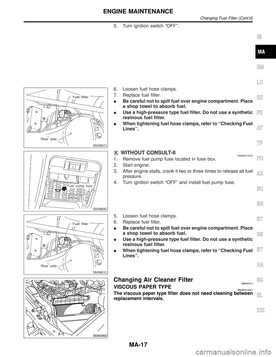
5. Turn ignition switch ªOFFº.
SMA861C
6. Loosen fuel hose clamps.
7. Replace fuel filter.
IBe careful not to spill fuel over engine compartment. Place
a shop towel to absorb fuel.
IUse a high-pressure type fuel filter. Do not use a synthetic
resinous fuel filter.
IWhen tightening fuel hose clamps, refer to ªChecking Fuel
Linesº.
SMA869C
WITHOUT CONSULT-IINBMA0013S021. Remove fuel pump fuse located in fuse box.
2. Start engine.
3. After engine stalls, crank it two or three times to release all fuel
pressure.
4. Turn ignition switch ªOFFº and install fuel pump fuse.
SMA861C
5. Loosen fuel hose clamps.
6. Replace fuel filter.
IBe careful not to spill fuel over engine compartment. Place
a shop towel to absorb fuel.
IUse a high-pressure type fuel filter. Do not use a synthetic
resinous fuel filter.
IWhen tightening fuel hose clamps, refer to ªChecking Fuel
Linesº.
SMA095D
Changing Air Cleaner FilterNBMA0014VISCOUS PAPER TYPENBMA0014S01The viscous paper type filter does not need cleaning between
replacement intervals.
GI
EM
LC
EC
FE
AT
TF
PD
AX
SU
BR
ST
RS
BT
HA
SC
EL
IDX
ENGINE MAINTENANCE
Changing Fuel Filter (Cont'd)
MA-17