Page 2048 of 2395
SPD647
SPD781
3. Remove grease seal and oil seal.
InspectionNBPD0019RING GEAR AND DRIVE PINIONNBPD0019S01Check gear teeth for scoring, cracking or chipping.
If any damaged part is evident, replace ring gear and drive pinion
as a set (hypoid gear set).
SPD097AA
DIFFERENTIAL CASE ASSEMBLYNBPD0019S02Check mating surfaces of differential case, side gears, pinion mate
gears, pinion mate shaft and thrust washers.
SPD715
BEARINGNBPD0019S031. Thoroughly clean bearing.
2. Check bearing for wear, scratches, pitting or flaking.
Check tapered roller bearing for smooth rotation. If damaged,
replace outer race and inner cone as a set.
GI
MA
EM
LC
EC
FE
AT
TF
AX
SU
BR
ST
RS
BT
HA
SC
EL
IDX
FRONT FINAL DRIVER200A
Disassembly (Cont'd)
PD-23
Page 2049 of 2395

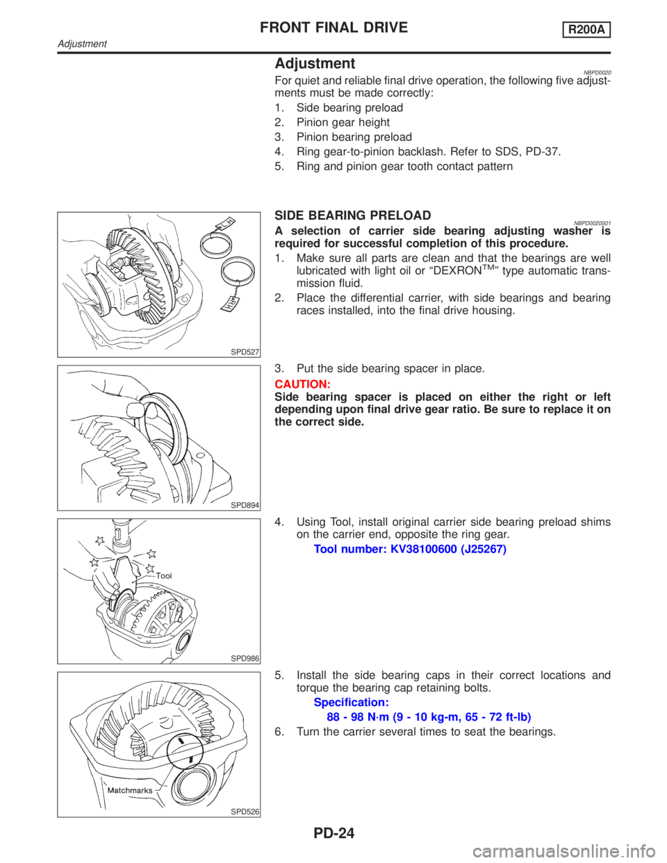
AdjustmentNBPD0020For quiet and reliable final drive operation, the following five adjust-
ments must be made correctly:
1. Side bearing preload
2. Pinion gear height
3. Pinion bearing preload
4. Ring gear-to-pinion backlash. Refer to SDS, PD-37.
5. Ring and pinion gear tooth contact pattern
SPD527
SIDE BEARING PRELOADNBPD0020S01A selection of carrier side bearing adjusting washer is
required for successful completion of this procedure.
1. Make sure all parts are clean and that the bearings are well
lubricated with light oil or ªDEXRON
TMº type automatic trans-
mission fluid.
2. Place the differential carrier, with side bearings and bearing
races installed, into the final drive housing.
SPD894
3. Put the side bearing spacer in place.
CAUTION:
Side bearing spacer is placed on either the right or left
depending upon final drive gear ratio. Be sure to replace it on
the correct side.
SPD986
4. Using Tool, install original carrier side bearing preload shims
on the carrier end, opposite the ring gear.
Tool number: KV38100600 (J25267)
SPD526
5. Install the side bearing caps in their correct locations and
torque the bearing cap retaining bolts.
Specification:
88 - 98 N´m (9 - 10 kg-m, 65 - 72 ft-lb)
6. Turn the carrier several times to seat the bearings.
FRONT FINAL DRIVER200A
Adjustment
PD-24
Page 2055 of 2395
SPD677
3. Hold companion flange steady by hand and rotate the ring gear
in both directions.
SPD007-B
SPD782-A
SPD654-A
AssemblyNBPD0021DIFFERENTIAL SIDE SHAFTNBPD0021S011. Install oil seal and grease seal.
FRONT FINAL DRIVER200A
Adjustment (Cont'd)
PD-30
Page 2056 of 2395
SPD655
2. Install extension tube retainer, rear axle bearing and rear axle
shaft bearing collar on differential side shaft.
SPD552
DIFFERENTIAL CASENBPD0021S021. Install side gears, pinion mate gears and thrust washers into
differential case.
SPD258
2. Fit pinion mate shaft to differential case so that it meets lock
pin holes.
3. Adjust backlash between side gear and pinion mate gear by
selecting side gear thrust washer.
Refer to SDS, PD-36.
Backlash between side gear and pinion mate gear
(Clearance between side gear thrust washer and differ-
ential case):
Less than 0.15 mm (0.0059 in)
SPD030
4. Install pinion mate shaft lock pin with a punch.
Make sure lock pin is flush with case.
SPD322
5. Apply gear oil to gear tooth surfaces and thrust surfaces and
check to see they turn properly.
GI
MA
EM
LC
EC
FE
AT
TF
AX
SU
BR
ST
RS
BT
HA
SC
EL
IDX
FRONT FINAL DRIVER200A
Assembly (Cont'd)
PD-31
Page 2057 of 2395
SPD554
6. Install differential case assembly on ring gear.
7. Apply locking agent [Locktite (stud lock) or equivalent] to ring
gear bolts, and install them.
Tighten bolts in a criss-cross pattern, lightly tapping bolt head
with a hammer.
PD353
8. Press-fit side bearing inner cones on differential case with Tool.
Tool number:
A KV38100300 (J25523)
B ST33061000 (J8107-2)
SPD679
FINAL DRIVE HOUSINGNBPD0021S031. Press-fit front and rear bearing outer races with Tools.
Tool number:
A ST30611000 (J25742-1)
B ST30621000 (J25742-5)
C ST30613000 (J25742-3)
SPD377
2. Select drive pinion height adjusting washer and pinion bearing
adjusting washer. Refer to ªPINION GEAR HEIGHT AND PIN-
ION BEARING PRELOADº, PD-25.
3. Install drive pinion height adjusting washer in drive pinion, and
press-fit pinion rear bearing inner cone in it, using press and
Tool.
Tool number:
ST30901000 (J26010-01)
FRONT FINAL DRIVER200A
Assembly (Cont'd)
PD-32
Page 2059 of 2395
SPD664
9. Turn drive pinion in both directions several revolutions, and
measure pinion bearing preload.
Tool number: ST3127S000 (J25765-A)
Pinion bearing preload:
1.1 - 1.4 N´m (11 - 14 kg-cm, 9.5 - 12.2 in-lb)
When pinion bearing preload is outside the specifications,
replace pinion bearing adjusting washer and spacer with a
different thickness.
SPD527
10. Select side bearing adjusting washer.
Refer to ªSIDE BEARING PRELOADº, PD-24.
11. Install differential case assembly with side bearing outer races
into final drive housing.
SPD558
12. Insert left and right side bearing adjusting washers in place
between side bearings and final drive housing.
SPD559
13. Drive in side bearing spacer with Tool.
Tool number: KV38100600 (J25267)
SPD526
14. Align mark on bearing cap with that on final drive housing and
install bearing cap on final drive housing.
FRONT FINAL DRIVER200A
Assembly (Cont'd)
PD-34
Page 2060 of 2395

SPD560
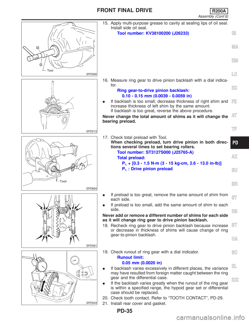
15. Apply multi-purpose grease to cavity at sealing lips of oil seal.
Install side oil seal.
Tool number: KV38100200 (J26233)
SPD513
16. Measure ring gear to drive pinion backlash with a dial indica-
tor.
Ring gear-to-drive pinion backlash:
0.10 - 0.15 mm (0.0039 - 0.0059 in)
IIf backlash is too small, decrease thickness of right shim and
increase thickness of left shim by the same amount.
If backlash is too great, reverse the above procedure.
Never change the total amount of shims as it will change the
bearing preload.
SPD664
17. Check total preload with Tool.
When checking preload, turn drive pinion in both direc-
tions several times to set bearing rollers.
Tool number: ST3127S000 (J25765-A)
Total preload:
P
1+ [0.3 - 1.5 N´m (3 - 15 kg-cm, 2.6 - 13.0 in-lb)]
P
1: Drive pinion preload
SPD561
IIf preload is too great, remove the same amount of shim from
each side.
IIf preload is too small, add the same amount of shim to each
side.
Never add or remove a different number of shims for each side
as it will change ring gear to drive pinion backlash.
18. Recheck ring gear to drive pinion backlash because increase
or decrease in thickness of shims will cause change of ring
gear-to-pinion backlash.
SPD524
19. Check runout of ring gear with a dial indicator.
Runout limit:
0.05 mm (0.0020 in)
IIf backlash varies excessively in different places, the variance
may have resulted from foreign matter caught between the ring
gear and the differential case.
IIf the backlash varies greatly when the runout of the ring gear
is within a specified range, the hypoid gear set or differential
case should be replaced.
20. Check tooth contact. Refer to ªTOOTH CONTACTº, PD-29.
21. Install rear cover and gasket.
GI
MA
EM
LC
EC
FE
AT
TF
AX
SU
BR
ST
RS
BT
HA
SC
EL
IDX
FRONT FINAL DRIVER200A
Assembly (Cont'd)
PD-35
Page 2061 of 2395

SPD682
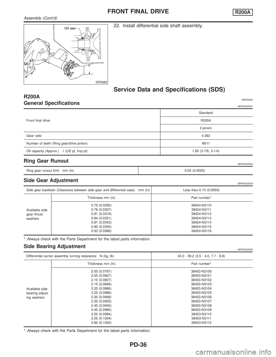
22. Install differential side shaft assembly.
Service Data and Specifications (SDS)
R200ANBPD0022General SpecificationsNBPD0022S01
Front final driveStandard
R200A
2-pinion
Gear ratio4.363
Number of teeth (Ring gear/drive pinion)48/11
Oil capacity (Approx.)(US pt, lmp pt) 1.85 (3-7/8, 3-1/4)
Ring Gear RunoutNBPD0022S02
Ring gear runout limit mm (in)0.05 (0.0020)
Side Gear AdjustmentNBPD0022S03
Side gear backlash (Clearance between side gear and differential case) mm (in) Less than 0.15 (0.0059)
Available side
gear thrust
washersThickness mm (in) Part number*
0.75 (0.0295)
0.78 (0.0307)
0.81 (0.0319)
0.84 (0.0331)
0.87 (0.0343)
0.90 (0.0354)
0.93 (0.0366)38424-N3110
38424-N3111
38424-N3112
38424-N3113
38424-N3114
38424-N3115
38424-N3116
*: Always check with the Parts Department for the latest parts information.
Side Bearing AdjustmentNBPD0022S04
Differential carrier assembly turning resistance N (kg, lb) 34.3 - 39.2 (3.5 - 4.0, 7.7 - 8.8)
Available side
bearing adjust-
ing washersThickness mm (in) Part number*
2.00 (0.0787)
2.05 (0.0807)
2.10 (0.0827)
2.15 (0.0846)
2.20 (0.0866)
2.25 (0.0886)
2.30 (0.0906)
2.35 (0.0925)
2.40 (0.0945)
2.45 (0.0965)
2.50 (0.0984)
2.55 (0.1004)
2.60 (0.1024)38453-N3100
38453-N3101
38453-N3102
38453-N3103
38453-N3104
38453-N3105
38453-N3106
38453-N3107
38453-N3108
38453-N3109
38453-N3110
38453-N3111
38453-N3112
*: Always check with the Parts Department for the latest parts information.
FRONT FINAL DRIVER200A
Assembly (Cont'd)
PD-36