Page 2027 of 2395
DISASSEMBLY........................................................48
INSPECTION...........................................................49
ADJUSTMENT.........................................................50
ASSEMBLY.............................................................51
Adjustment .................................................................53
PINION GEAR HEIGHT............................................53
TOOTH CONTACT...................................................56Assembly ...................................................................57
DIFFERENTIAL CASE..............................................57
DIFFERENTIAL CARRIER........................................58
Service Data and Specifications (SDS).....................62
H233B.....................................................................62
CONTENTS(Cont'd)
PD-2
Page 2028 of 2395

Noise, Vibration and Harshness (NVH)
Troubleshooting
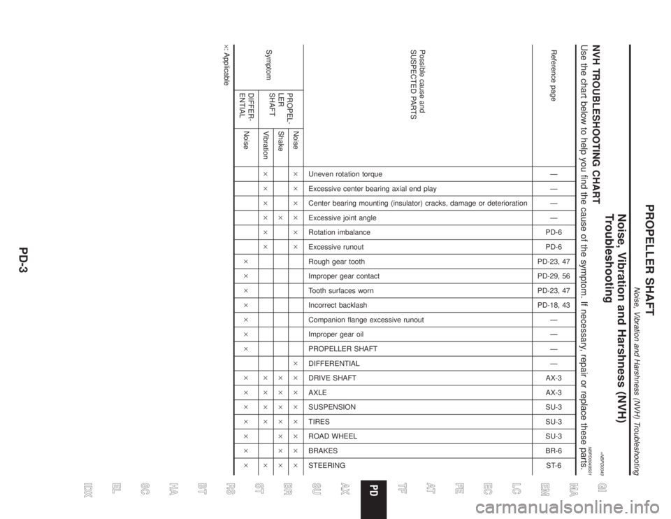
=NBPD0049NVH TROUBLESHOOTING CHARTNBPD0049S01Use the chart below to help you find the cause of the symptom. If necessary, repair or replace these parts.
Reference pageÐ
Ð
Ð
Ð
PD-6
PD-6
PD-23, 47
PD-29, 56
PD-23, 47
PD-18, 43
Ð
Ð
Ð
Ð
AX-3
AX-3
SU-3
SU-3
SU-3
BR-6
ST-6
Possible cause and
SUSPECTED PARTS
Uneven rotation torque
Excessive center bearing axial end play
Center bearing mounting (insulator) cracks, damage or deterioration
Excessive joint angle
Rotation imbalance
Excessive runout
Rough gear tooth
Improper gear contact
Tooth surfaces worn
Incorrect backlash
Companion flange excessive runout
Improper gear oil
PROPELLER SHAFT
DIFFERENTIAL
DRIVE SHAFT
AXLE
SUSPENSION
TIRES
ROAD WHEEL
BRAKES
STEERING
SymptomPROPEL-
LER
SHAFTNoise´´´´´´ ´´´´´´´´
Shake´ ´´´´´´´
Vibration´´´´´´ ´´´´ ´
DIFFER-
ENTIALNoise´´´´´´´ ´´´´´´´
´: Applicable
GI
MA
EM
LC
EC
FE
AT
TF
AX
SU
BR
ST
RS
BT
HA
SC
EL
IDX
PROPELLER SHAFT
Noise, Vibration and Harshness (NVH) Troubleshooting
PD-3
Page 2038 of 2395

Preparation
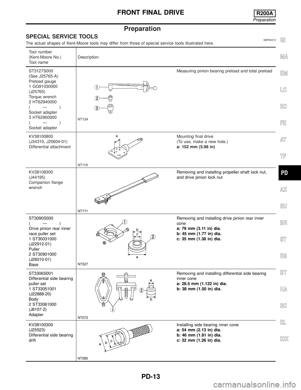
SPECIAL SERVICE TOOLSNBPD0013The actual shapes of Kent-Moore tools may differ from those of special service tools illustrated here.
Tool number
(Kent-Moore No.)
Tool nameDescription
ST3127S000
(See J25765-A)
Preload gauge
1 GG91030000
(J25765)
Torque wrench
2 HT62940000
(Ð)
Socket adapter
3 HT62900000
(Ð)
Socket adapter
NT124
Measuring pinion bearing preload and total preload
KV38100800
(J34310, J25604-01)
Differential attachment
NT119
Mounting final drive
(To use, make a new hole.)
a: 152 mm (5.98 in)
KV38108300
(J44195)
Companion flange
wrench
NT771
Removing and installing propeller shaft lock nut,
and drive pinion lock nut
ST3090S000
(Ð)
Drive pinion rear inner
race puller set
1 ST30031000
(J22912-01)
Puller
2 ST30901000
(J26010-01)
Base
NT527
Removing and installing drive pinion rear inner
cone
a: 79 mm (3.11 in) dia.
b: 45 mm (1.77 in) dia.
c: 35 mm (1.38 in) dia.
ST3306S001
Differential side bearing
puller set
1 ST33051001
(J22888-20)
Body
2 ST33061000
(J8107-2)
Adapter
NT072
Removing and installing differential side bearing
inner cone
a: 28.5 mm (1.122 in) dia.
b: 38 mm (1.50 in) dia.
KV38100300
(J25523)
Differential side bearing
drift
NT085
Installing side bearing inner cone
a: 54 mm (2.13 in) dia.
b: 46 mm (1.81 in) dia.
c: 32 mm (1.26 in) dia.
GI
MA
EM
LC
EC
FE
AT
TF
AX
SU
BR
ST
RS
BT
HA
SC
EL
IDX
FRONT FINAL DRIVER200A
Preparation
PD-13
Page 2039 of 2395

Tool number
(Kent-Moore No.)
Tool nameDescription
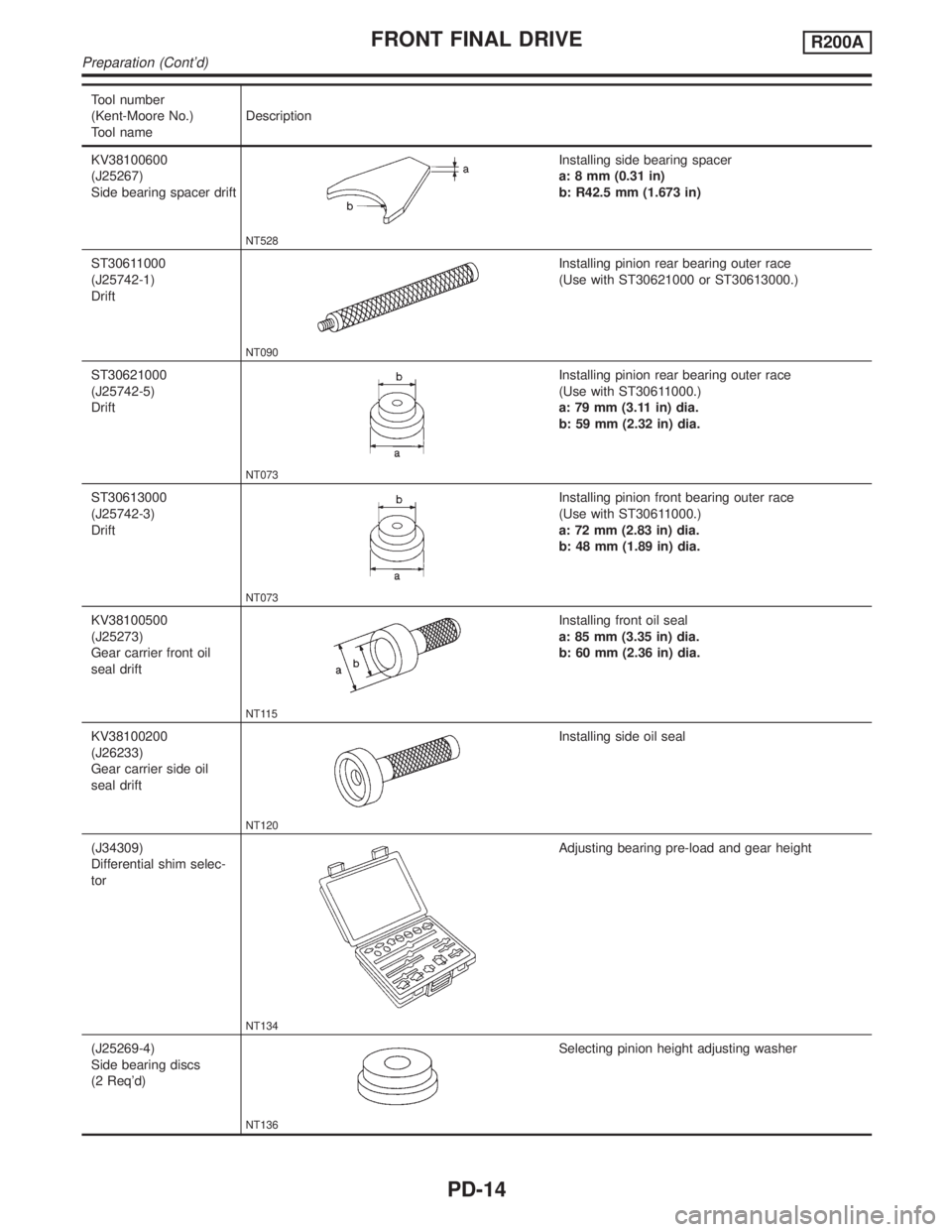
KV38100600
(J25267)
Side bearing spacer drift
NT528
Installing side bearing spacer
a: 8 mm (0.31 in)
b: R42.5 mm (1.673 in)
ST30611000
(J25742-1)
Drift
NT090
Installing pinion rear bearing outer race
(Use with ST30621000 or ST30613000.)
ST30621000
(J25742-5)
Drift
NT073
Installing pinion rear bearing outer race
(Use with ST30611000.)
a: 79 mm (3.11 in) dia.
b: 59 mm (2.32 in) dia.
ST30613000
(J25742-3)
Drift
NT073
Installing pinion front bearing outer race
(Use with ST30611000.)
a: 72 mm (2.83 in) dia.
b: 48 mm (1.89 in) dia.
KV38100500
(J25273)
Gear carrier front oil
seal drift
NT115
Installing front oil seal
a: 85 mm (3.35 in) dia.
b: 60 mm (2.36 in) dia.
KV38100200
(J26233)
Gear carrier side oil
seal drift
NT120
Installing side oil seal
(J34309)
Differential shim selec-
tor
NT134
Adjusting bearing pre-load and gear height
(J25269-4)
Side bearing discs
(2 Req'd)
NT136
Selecting pinion height adjusting washer
FRONT FINAL DRIVER200A
Preparation (Cont'd)
PD-14
Page 2044 of 2395
SPD524
IRing gear runout
Check runout of ring gear with a dial indicator.
Runout limit:
0.05 mm (0.0020 in)
ITooth contact
Check tooth contact. Refer to ªTOOTH CONTACTº, PD-29.
SPD665
ISide gear to pinion mate gear backlash
Using a feeler gauge, measure clearance between side gear
thrust washer and differential case.
Clearance between side gear thrust washer and differ-
ential case:
Less than 0.15 mm (0.0059 in)
SPD666
FINAL DRIVE HOUSINGNBPD0018S021. Using three spacers [20 mm (0.79 in)], mount final drive
assembly on Tool.
Tool number:
KV38100800 (J34310, J25604-01)
SPD644
2. Remove differential side shaft assembly.
SPD667
3. Remove differential side flange.
GI
MA
EM
LC
EC
FE
AT
TF
AX
SU
BR
ST
RS
BT
HA
SC
EL
IDX
FRONT FINAL DRIVER200A
Disassembly (Cont'd)
PD-19
Page 2045 of 2395
SPD526
4. Put matchmarks on one side of side bearing cap with paint or
punch to ensure that it is replaced in proper position during
reassembly.
Bearing caps are line-bored during manufacture and should
be put back in their original places.
PD343
5. Remove side bearing caps.
SPD668
6. Remove differential case assembly with a pry bar.
SPD527
Be careful to keep the side bearing outer races together with
their respective inner cones Ð do not mix them up.
CAUTION:
Side bearing spacer is placed on either the left or right
depending upon final drive gear ratio. It should be labeled so
that it may be replaced correctly.
SPD477A
7. Loosen drive pinion nut.
Tool number: KV38108300 (J44195)
8. Remove companion flange with puller.
FRONT FINAL DRIVER200A
Disassembly (Cont'd)
PD-20
Page 2046 of 2395
SPD670
9. Take out drive pinion together with rear bearing inner cone,
drive pinion bearing spacer and pinion bearing adjusting
washer.
10. Remove front oil seal and pinion front bearing inner cone.
PD349
11. Remove pinion bearing outer races with a brass drift.
SPD209
12. Remove pinion rear bearing inner cone and drive pinion height
adjusting washer.
Tool number: ST30031000 (J22912-01)
SPD207A
DIFFERENTIAL CASENBPD0018S031. Remove side bearing inner cones.
To prevent damage to bearing, engage puller jaws in grooves.
Tool number:
A ST33051001 (J22888-20)
B ST33061000 (J8107-2)
SPD022
Be careful not to confuse the right and left hand parts.
Keep bearing and bearing race for each side together.
GI
MA
EM
LC
EC
FE
AT
TF
AX
SU
BR
ST
RS
BT
HA
SC
EL
IDX
FRONT FINAL DRIVER200A
Disassembly (Cont'd)
PD-21
Page 2047 of 2395
SPD024
2. Loosen ring gear bolts in a criss-cross pattern.
3. Tap ring gear off the differential case with a soft hammer.
Tap evenly all around to keep ring gear from binding.
SPD025
4. Punch off pinion mate shaft lock pin from ring gear side.
SPD236A
DIFFERENTIAL SIDE SHAFTNBPD0018S041. Cut collar with cold chisel. Be careful not to damage differen-
tial side shaft.
SPD672
2. Reinstall differential side shaft into extension tube and secure
with bolts. Remove rear axle bearing by drawing out differen-
tial side shaft from rear axle bearing with puller.
FRONT FINAL DRIVER200A
Disassembly (Cont'd)
PD-22