2001 INFINITI QX4 elec
[x] Cancel search: elecPage 1189 of 2395
Supplemental Restraint System (SRS) ªAIR
BAGº and ªSEAT BELT PRE-TENSIONERº
NBEL0001The Supplemental Restraint System such as ªAIR BAGº and ªSEAT BELT PRE-TENSIONERº used along with
a seat belt, helps to reduce the risk or severity of injury to the driver and front passenger for certain types of
collision. The SRS system composition which is available to INFINITI QX4 is as follows:
IFor a frontal collision
The Supplemental Restraint System consists of driver air bag module (located in the center of the steer-
ing wheel), front passenger air bag module (located on the instrument panel on passenger side), seat belt
pre-tensioners, a diagnosis sensor unit, warning lamp, wiring harness and spiral cable.
IFor a side collision
The Supplemental Restraint System consists of side air bag module (located in the outer side of front seat),
satellite sensor, diagnosis sensor unit (one of components of air bags for a frontal collision), wiring harness,
warning lamp (one of components of air bags for a frontal collision).
Information necessary to service the system safely is included in theRS sectionof this Service Manual.
WARNING:
ITo avoid rendering the SRS inoperative, which could increase the risk of personal injury or death
in the event of a collision which would result in air bag inflation, all maintenance must be performed
by an authorized INFINITI dealer.
IImproper maintenance, including incorrect removal and installation of the SRS, can lead to per-
sonal injury caused by unintentional activation of the system. For removal of Spiral Cable and Air
Bag Module, see the RS section.
IDo not use electrical test equipment on any circuit related to the SRS unless instructed to in this
Service Manual. Spiral cable and wiring harnesses covered with yellow insulation tape either just
before the harness connectors or for the complete harness are related to the SRS.
Wiring Diagrams and Trouble DiagnosisNBEL0002When you read wiring diagrams, refer to the following:
IGI-11, ªHOW TO READ WIRING DIAGRAMSº
IEL-9, ªPOWER SUPPLY ROUTINGº for power distribution circuit
When you perform trouble diagnosis, refer to the following:
IGI-35, ªHOW TO FOLLOW TEST GROUPS IN TROUBLE DIAGNOSESº
IGI-24, ªHOW TO PERFORM EFFICIENT DIAGNOSIS FOR AN ELECTRICAL INCIDENTº
Check for any Service bulletins before servicing the vehicle.
PRECAUTIONS
Supplemental Restraint System (SRS) ªAIR BAGº and ªSEAT BELT PRE-TENSIONERº
EL-4
Page 1201 of 2395

CEL083
InspectionNBEL0007FUSENBEL0007S01IIf fuse is blown, be sure to eliminate cause of problem
before installing new fuse.
IUse fuse of specified rating. Never use fuse of more than
specified rating.
IDo not partially install fuse; always insert it into fuse
holder properly.
IRemove fuse for ªELECTRICAL PARTS (BAT)º if vehicle is
not used for a long period of time.
MEL944F
FUSIBLE LINKNBEL0007S02A melted fusible link can be detected either by visual inspection or
by feeling with finger tip. If its condition is questionable, use circuit
tester or test lamp.
CAUTION:
IIf fusible link should melt, it is possible that critical circuit
(power supply or large current carrying circuit) is shorted.
In such a case, carefully check and eliminate cause of
problem.
INever wrap outside of fusible link with vinyl tape. Impor-
tant: Never let fusible link touch any other wiring harness,
vinyl or rubber parts.
SEL109W
CIRCUIT BREAKER (PTC THERMISTOR TYPE)NBEL0007S03The PTC thermister generates heat in response to current flow.
The temperature (and resistance) of the thermister element varies
with current flow. Excessive current flow will cause the element's
temperature to rise. When the temperature reaches a specified
level, the electrical resistance will rise sharply to control the circuit
current.
Reduced current flow will cause the element to cool. Resistance
falls accordingly and normal circuit current flow is allowed to
resume.
POWER SUPPLY ROUTING
Inspection
EL-16
Page 1219 of 2395
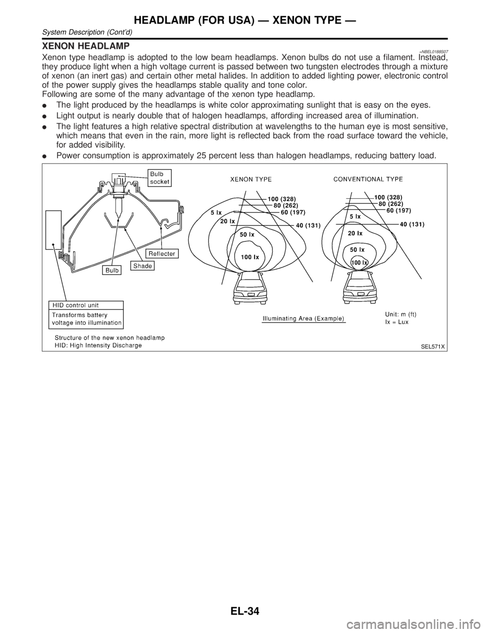
XENON HEADLAMP=NBEL0188S07Xenon type headlamp is adopted to the low beam headlamps. Xenon bulbs do not use a filament. Instead,
they produce light when a high voltage current is passed between two tungsten electrodes through a mixture
of xenon (an inert gas) and certain other metal halides. In addition to added lighting power, electronic control
of the power supply gives the headlamps stable quality and tone color.
Following are some of the many advantage of the xenon type headlamp.
IThe light produced by the headlamps is white color approximating sunlight that is easy on the eyes.
ILight output is nearly double that of halogen headlamps, affording increased area of illumination.
IThe light features a high relative spectral distribution at wavelengths to the human eye is most sensitive,
which means that even in the rain, more light is reflected back from the road surface toward the vehicle,
for added visibility.
IPower consumption is approximately 25 percent less than halogen headlamps, reducing battery load.
SEL571X
HEADLAMP (FOR USA) Ð XENON TYPE Ð
System Description (Cont'd)
EL-34
Page 1241 of 2395
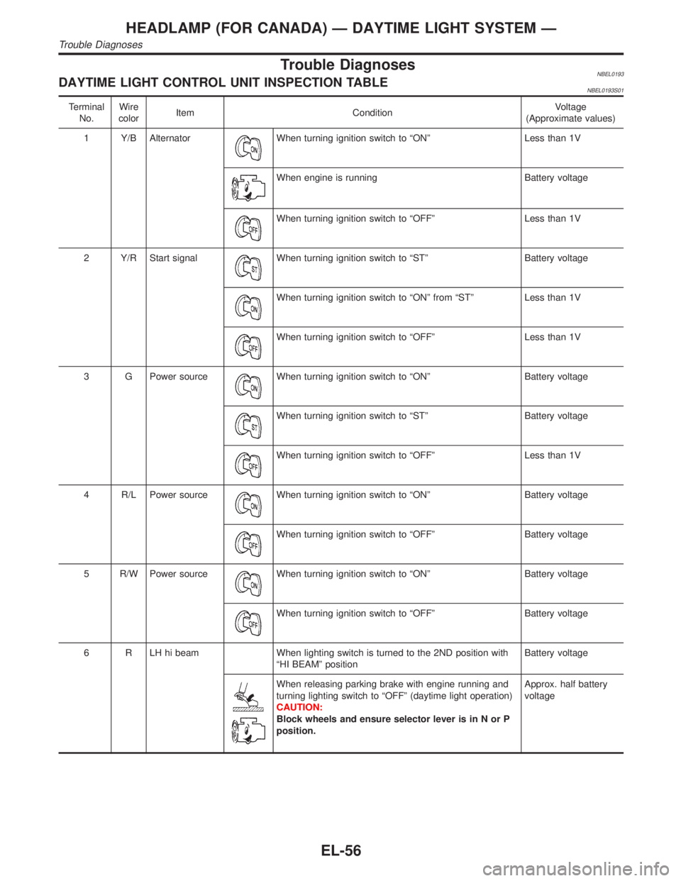
Trouble DiagnosesNBEL0193DAYTIME LIGHT CONTROL UNIT INSPECTION TABLENBEL0193S01
Terminal
No.Wire
colorItem ConditionVoltage
(Approximate values)
1 Y/B Alternator
When turning ignition switch to ªONº Less than 1V
When engine is running Battery voltage
When turning ignition switch to ªOFFº Less than 1V
2 Y/R Start signal
When turning ignition switch to ªSTº Battery voltage
When turning ignition switch to ªONº from ªSTº Less than 1V
When turning ignition switch to ªOFFº Less than 1V
3 G Power source
When turning ignition switch to ªONº Battery voltage
When turning ignition switch to ªSTº Battery voltage
When turning ignition switch to ªOFFº Less than 1V
4 R/L Power source
When turning ignition switch to ªONº Battery voltage
When turning ignition switch to ªOFFº Battery voltage
5 R/W Power source
When turning ignition switch to ªONº Battery voltage
When turning ignition switch to ªOFFº Battery voltage
6 R LH hi beam When lighting switch is turned to the 2ND position with
ªHI BEAMº positionBattery voltage
When releasing parking brake with engine running and
turning lighting switch to ªOFFº (daytime light operation)
CAUTION:
Block wheels and ensure selector lever is in N or P
position.Approx. half battery
voltage
HEADLAMP (FOR CANADA) Ð DAYTIME LIGHT SYSTEM Ð
Trouble Diagnoses
EL-56
Page 1242 of 2395
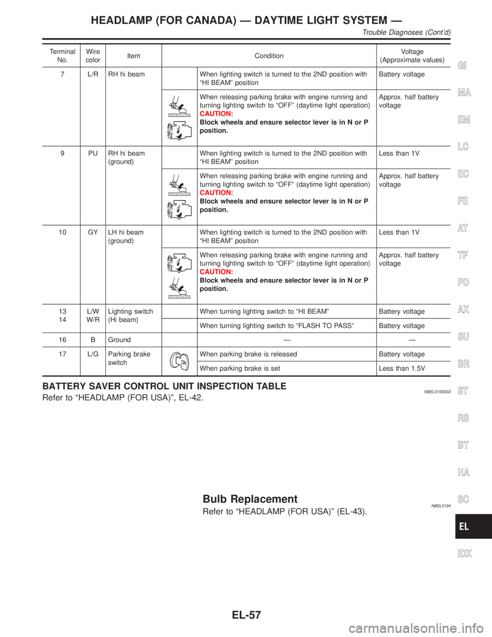
Terminal
No.Wire
colorItem ConditionVoltage
(Approximate values)
7 L/R RH hi beam When lighting switch is turned to the 2ND position with
ªHI BEAMº positionBattery voltage
When releasing parking brake with engine running and
turning lighting switch to ªOFFº (daytime light operation)
CAUTION:
Block wheels and ensure selector lever is in N or P
position.Approx. half battery
voltage
9 PU RH hi beam
(ground)When lighting switch is turned to the 2ND position with
ªHI BEAMº positionLess than 1V
When releasing parking brake with engine running and
turning lighting switch to ªOFFº (daytime light operation)
CAUTION:
Block wheels and ensure selector lever is in N or P
position.Approx. half battery
voltage
10 GY LH hi beam
(ground)When lighting switch is turned to the 2ND position with
ªHI BEAMº positionLess than 1V
When releasing parking brake with engine running and
turning lighting switch to ªOFFº (daytime light operation)
CAUTION:
Block wheels and ensure selector lever is in N or P
position.Approx. half battery
voltage
13
14L/W
W/RLighting switch
(Hi beam)When turning lighting switch to ªHI BEAMº Battery voltage
When turning lighting switch to ªFLASH TO PASSº Battery voltage
16 B Ground Ð Ð
17 L/G Parking brake
switch
When parking brake is released Battery voltage
When parking brake is set Less than 1.5V
BATTERY SAVER CONTROL UNIT INSPECTION TABLENBEL0193S02Refer to ªHEADLAMP (FOR USA)º, EL-42.
Bulb ReplacementNBEL0194Refer to ªHEADLAMP (FOR USA)º (EL-43).
GI
MA
EM
LC
EC
FE
AT
TF
PD
AX
SU
BR
ST
RS
BT
HA
SC
IDX
HEADLAMP (FOR CANADA) Ð DAYTIME LIGHT SYSTEM Ð
Trouble Diagnoses (Cont'd)
EL-57
Page 1264 of 2395
Trouble DiagnosesNBEL0033
Symptom Possible cause Repair order
Turn signal and hazard warning
lamps do not operate.1. Hazard switch
2. Combination flasher unit
3. Open in combination flasher
unit circuit1. Check hazard switch.
2. Refer to combination flasher unit check.
3. Check wiring to combination flasher unit for open
circuit.
Turn signal lamps do not operate
but hazard warning lamps operate.1. 7.5A fuse
2. Hazard switch
3. Combination switch (turn signal)
4. Open in combination switch
(turn signal) circuit1. Check 7.5A fuse [No. 12, located in fuse block
(J/B)]. Turn ignition switch ON and verify battery
positive voltage is present at terminal 2 of hazard
switch.
2. Check hazard switch.
3. Check combination switch (turn signal).
4. Check the wire between combination flasher unit
terminal 3 and combination switch (turn signal) ter-
minal 1 for open circuit.
Hazard warning lamps do not oper-
ate but fog lamps (turn signal)
operate.1. 15A fuse
2. Hazard switch
3. Open in hazard switch circuit1. Check 15A fuse [No. 20, located in fuse block (J/B)].
Verify battery positive voltage is present at terminal
3 of hazard switch.
2. Check hazard switch.
3. Check the wire between combination flasher unit
terminal 3 and hazard switch terminal 4 for open cir-
cuit.
Front fog lamp (turn signal) LH or
RH does not operate.1. Bulb
2. Grounds E13 and E41
3. Open in front fog lamp (turn sig-
nal) circuit1. Check bulb.
2. Check grounds E13 and E41.
3. Check harness between front fog lamp (turn signal)
and combination switch.
Rear combination lamp LH does
not operate.1. Bulb
2. Grounds B11, B22 and D210
3. Open in rear combination lamp
LH circuit1. Check bulb.
2. Check grounds B11, B22 and D210.
3. Check harness between rear combination lamp LH
and hazard switch.
Rear combination lamp RH does
not operate.1. Bulb
2. Grounds B55 and B75
3. Open in rear combination lamp
RH circuit1. Check bulb.
2. Check grounds B55 and B75.
3. Check harness between rear combination lamp RH
and hazard switch.
LH and RH turn indicators do not
operate.1. Ground 1. Check grounds M4, M66 and M147.
LH or RH turn indicator does not
operate.1. Bulb
2. Open in turn indicator circuit1. Check bulb in combination meter.
2. Check harness between combination meter and haz-
ard switch.
SEL122E
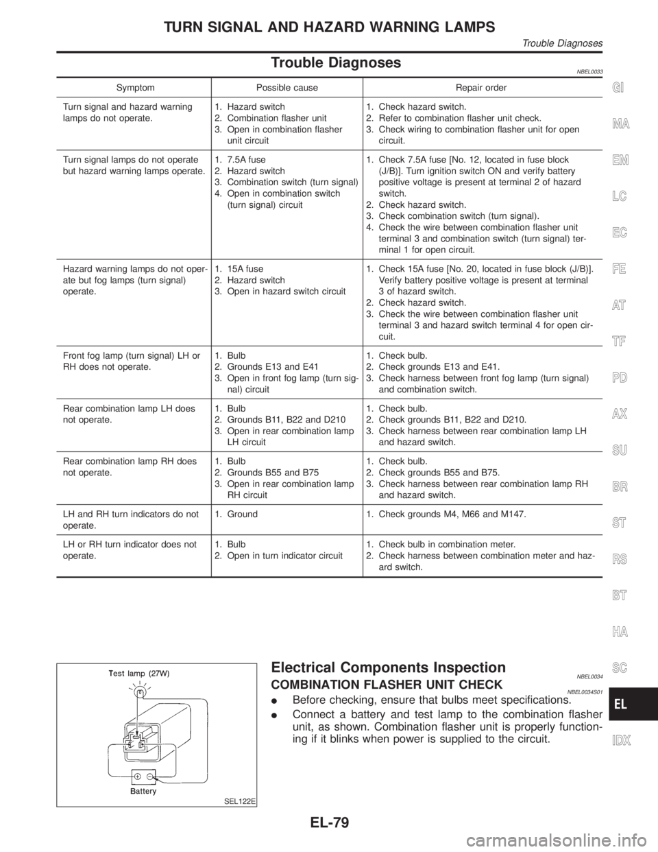
Electrical Components InspectionNBEL0034COMBINATION FLASHER UNIT CHECKNBEL0034S01IBefore checking, ensure that bulbs meet specifications.
IConnect a battery and test lamp to the combination flasher
unit, as shown. Combination flasher unit is properly function-
ing if it blinks when power is supplied to the circuit.
GI
MA
EM
LC
EC
FE
AT
TF
PD
AX
SU
BR
ST
RS
BT
HA
SC
IDX
TURN SIGNAL AND HAZARD WARNING LAMPS
Trouble Diagnoses
EL-79
Page 1293 of 2395
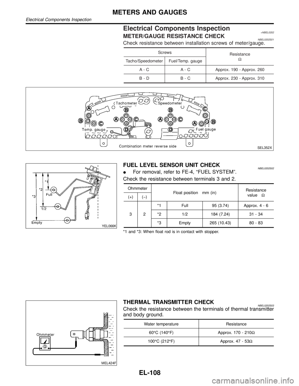
Electrical Components Inspection=NBEL0202METER/GAUGE RESISTANCE CHECKNBEL0202S01Check resistance between installation screws of meter/gauge.
Screws
Resistance
W
Tacho/Speedometer Fuel/Temp. gauge
A - C A - C Approx. 190 - Approx. 260
B - D B - C Approx. 230 - Approx. 310
SEL352X
YEL066K
FUEL LEVEL SENSOR UNIT CHECKNBEL0202S02IFor removal, refer to FE-4, ªFUEL SYSTEMº.
Check the resistance between terminals 3 and 2.
Ohmmeter
Float position mm (in)Resistance
valueW
(+) (þ)
32*1 Full 95 (3.74) Approx.4-6
*2 1/2 184 (7.24) 31 - 34
*3 Empty 265 (10.43) 80 - 83
*1 and *3: When float rod is in contact with stopper.
MEL424F
THERMAL TRANSMITTER CHECKNBEL0202S03Check the resistance between the terminals of thermal transmitter
and body ground.
Water temperature Resistance
60ÉC (140ÉF) Approx. 170 - 210W
100ÉC (212ÉF) Approx. 47 - 53W
METERS AND GAUGES
Electrical Components Inspection
EL-108
Page 1294 of 2395
MEL005H
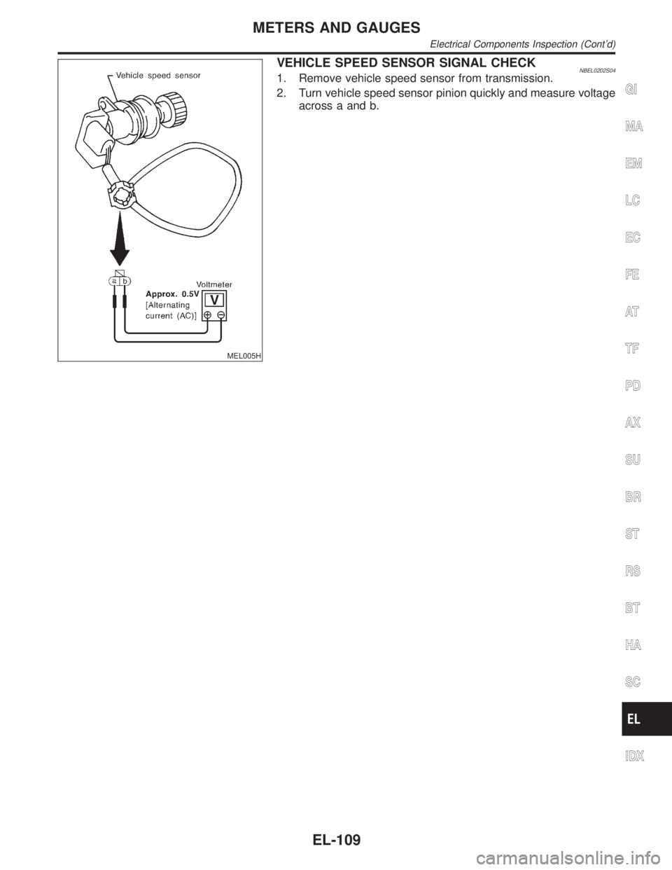
VEHICLE SPEED SENSOR SIGNAL CHECKNBEL0202S041. Remove vehicle speed sensor from transmission.
2. Turn vehicle speed sensor pinion quickly and measure voltage
across a and b.
GI
MA
EM
LC
EC
FE
AT
TF
PD
AX
SU
BR
ST
RS
BT
HA
SC
IDX
METERS AND GAUGES
Electrical Components Inspection (Cont'd)
EL-109