2001 INFINITI QX4 elec
[x] Cancel search: elecPage 1179 of 2395

Wiring DiagramNBEC0604
MEC421D
ELECTRICAL LOAD SIGNAL
Wiring Diagram
EC-644
Page 1180 of 2395
Diagnostic ProcedureNBEC0605
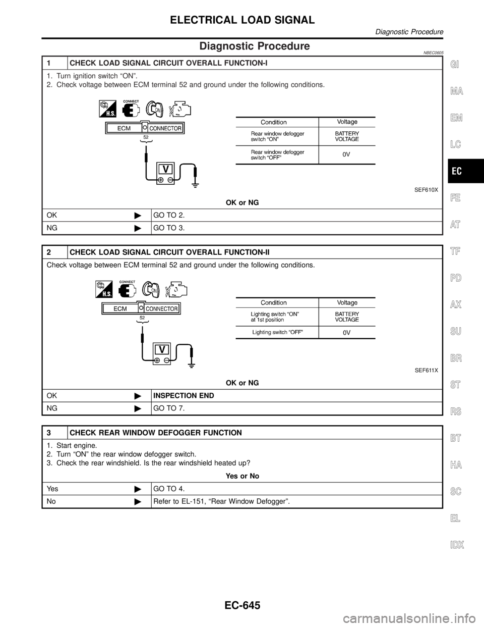
1 CHECK LOAD SIGNAL CIRCUIT OVERALL FUNCTION-I
1. Turn ignition switch ªONº.
2. Check voltage between ECM terminal 52 and ground under the following conditions.
SEF610X
OK or NG
OK©GO TO 2.
NG©GO TO 3.
2 CHECK LOAD SIGNAL CIRCUIT OVERALL FUNCTION-II
Check voltage between ECM terminal 52 and ground under the following conditions.
SEF611X
OK or NG
OK©INSPECTION END
NG©GO TO 7.
3 CHECK REAR WINDOW DEFOGGER FUNCTION
1. Start engine.
2. Turn ªONº the rear window defogger switch.
3. Check the rear windshield. Is the rear windshield heated up?
YesorNo
Ye s©GO TO 4.
No©Refer to EL-151, ªRear Window Defoggerº.
GI
MA
EM
LC
FE
AT
TF
PD
AX
SU
BR
ST
RS
BT
HA
SC
EL
IDX
ELECTRICAL LOAD SIGNAL
Diagnostic Procedure
EC-645
Page 1181 of 2395
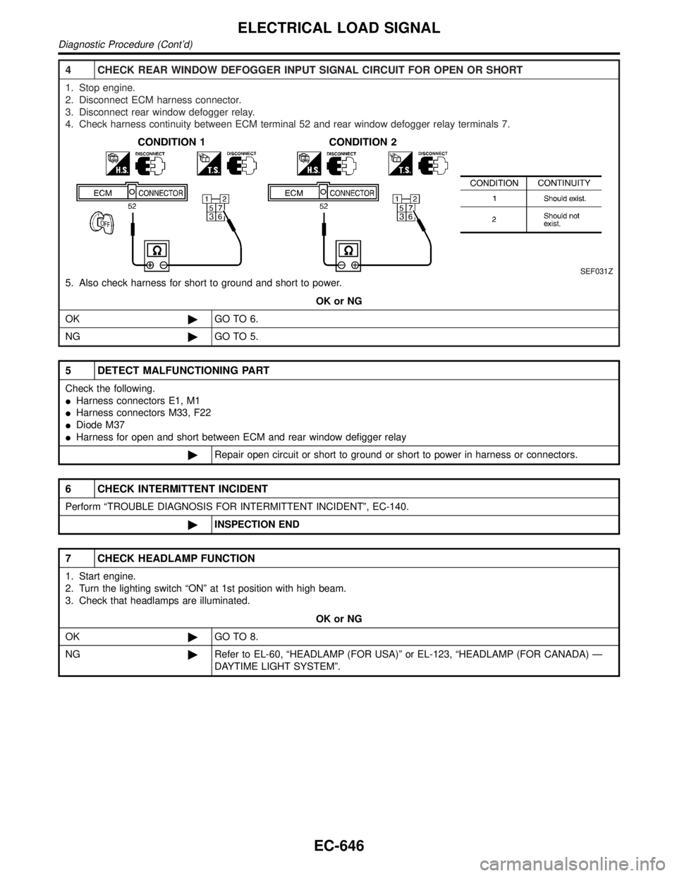
4 CHECK REAR WINDOW DEFOGGER INPUT SIGNAL CIRCUIT FOR OPEN OR SHORT
1. Stop engine.
2. Disconnect ECM harness connector.
3. Disconnect rear window defogger relay.
4. Check harness continuity between ECM terminal 52 and rear window defogger relay terminals 7.
SEF031Z
5. Also check harness for short to ground and short to power.
OK or NG
OK©GO TO 6.
NG©GO TO 5.
5 DETECT MALFUNCTIONING PART
Check the following.
IHarness connectors E1, M1
IHarness connectors M33, F22
IDiode M37
IHarness for open and short between ECM and rear window defigger relay
©Repair open circuit or short to ground or short to power in harness or connectors.
6 CHECK INTERMITTENT INCIDENT
Perform ªTROUBLE DIAGNOSIS FOR INTERMITTENT INCIDENTº, EC-140.
©INSPECTION END
7 CHECK HEADLAMP FUNCTION
1. Start engine.
2. Turn the lighting switch ªONº at 1st position with high beam.
3. Check that headlamps are illuminated.
OK or NG
OK©GO TO 8.
NG©Refer to EL-60, ªHEADLAMP (FOR USA)º or EL-123, ªHEADLAMP (FOR CANADA) Ð
DAYTIME LIGHT SYSTEMº.
ELECTRICAL LOAD SIGNAL
Diagnostic Procedure (Cont'd)
EC-646
Page 1182 of 2395
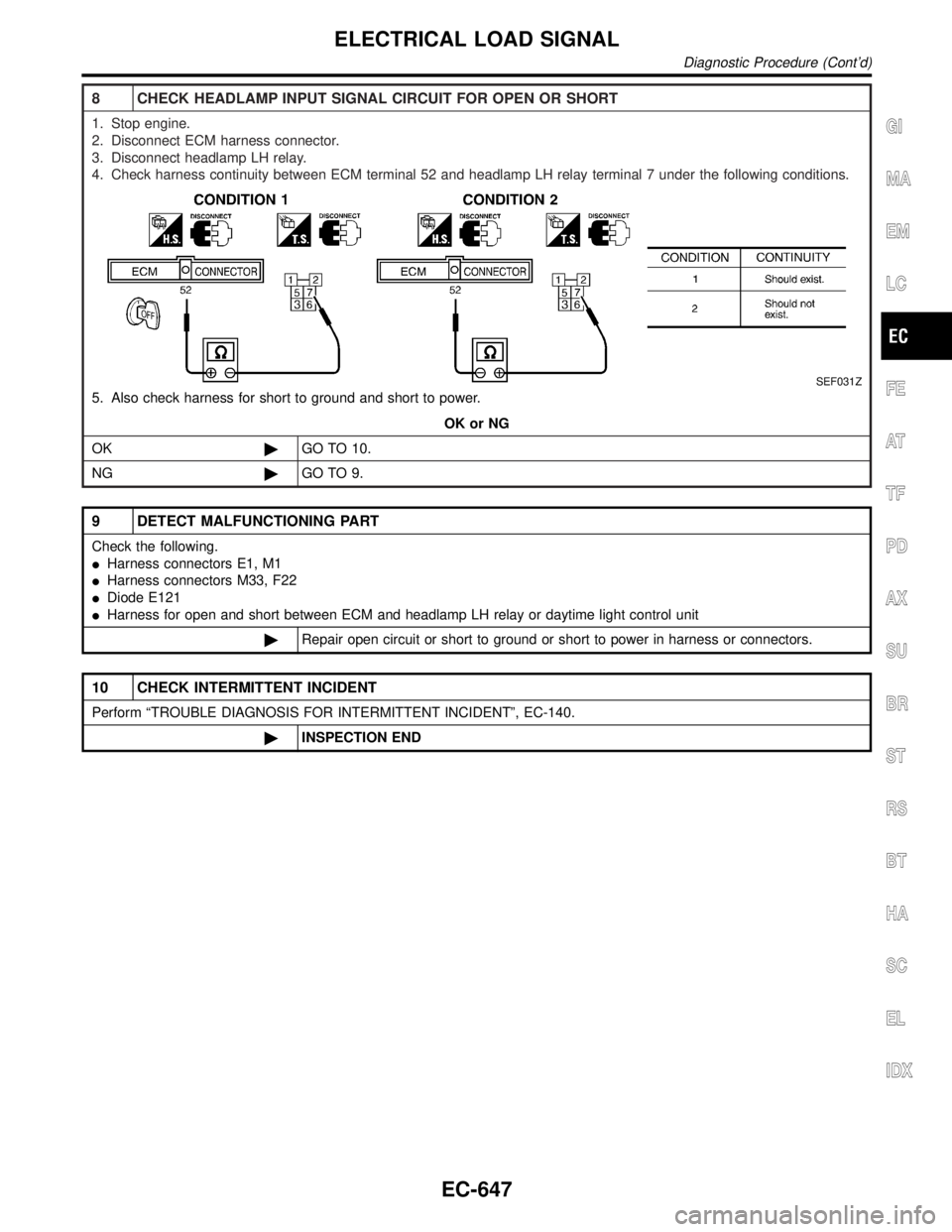
8 CHECK HEADLAMP INPUT SIGNAL CIRCUIT FOR OPEN OR SHORT
1. Stop engine.
2. Disconnect ECM harness connector.
3. Disconnect headlamp LH relay.
4. Check harness continuity between ECM terminal 52 and headlamp LH relay terminal 7 under the following conditions.
SEF031Z
5. Also check harness for short to ground and short to power.
OK or NG
OK©GO TO 10.
NG©GO TO 9.
9 DETECT MALFUNCTIONING PART
Check the following.
IHarness connectors E1, M1
IHarness connectors M33, F22
IDiode E121
IHarness for open and short between ECM and headlamp LH relay or daytime light control unit
©Repair open circuit or short to ground or short to power in harness or connectors.
10 CHECK INTERMITTENT INCIDENT
Perform ªTROUBLE DIAGNOSIS FOR INTERMITTENT INCIDENTº, EC-140.
©INSPECTION END
GI
MA
EM
LC
FE
AT
TF
PD
AX
SU
BR
ST
RS
BT
HA
SC
EL
IDX
ELECTRICAL LOAD SIGNAL
Diagnostic Procedure (Cont'd)
EC-647
Page 1184 of 2395
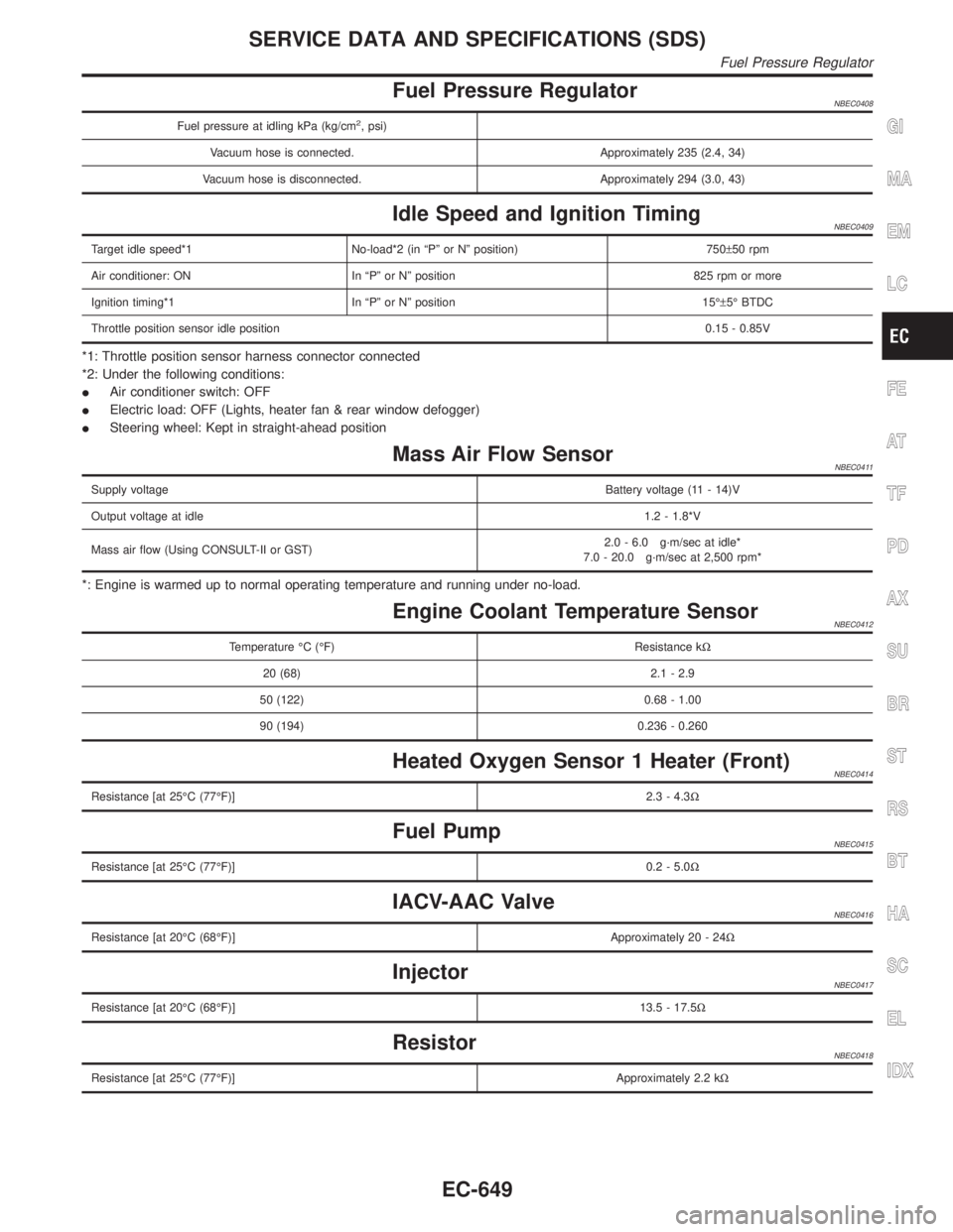
Fuel Pressure RegulatorNBEC0408
Fuel pressure at idling kPa (kg/cm2, psi)
Vacuum hose is connected. Approximately 235 (2.4, 34)
Vacuum hose is disconnected. Approximately 294 (3.0, 43)
Idle Speed and Ignition TimingNBEC0409
Target idle speed*1 No-load*2 (in ªPº or Nº position) 750±50 rpm
Air conditioner: ON In ªPº or Nº position 825 rpm or more
Ignition timing*1 In ªPº or Nº position 15ɱ5É BTDC
Throttle position sensor idle position0.15 - 0.85V
*1: Throttle position sensor harness connector connected
*2: Under the following conditions:
IAir conditioner switch: OFF
IElectric load: OFF (Lights, heater fan & rear window defogger)
ISteering wheel: Kept in straight-ahead position
Mass Air Flow SensorNBEC0411
Supply voltageBattery voltage (11 - 14)V
Output voltage at idle1.2 - 1.8*V
Mass air flow (Using CONSULT-II or GST)2.0 - 6.0 g´m/sec at idle*
7.0 - 20.0 g´m/sec at 2,500 rpm*
*: Engine is warmed up to normal operating temperature and running under no-load.
Engine Coolant Temperature SensorNBEC0412
Temperature ÉC (ÉF) Resistance kW
20 (68) 2.1 - 2.9
50 (122) 0.68 - 1.00
90 (194) 0.236 - 0.260
Heated Oxygen Sensor 1 Heater (Front)NBEC0414
Resistance [at 25ÉC (77ÉF)]2.3 - 4.3W
Fuel PumpNBEC0415
Resistance [at 25ÉC (77ÉF)]0.2 - 5.0W
IACV-AAC ValveNBEC0416
Resistance [at 20ÉC (68ÉF)]Approximately 20 - 24W
InjectorNBEC0417
Resistance [at 20ÉC (68ÉF)]13.5 - 17.5W
ResistorNBEC0418
Resistance [at 25ÉC (77ÉF)]Approximately 2.2 kW
GI
MA
EM
LC
FE
AT
TF
PD
AX
SU
BR
ST
RS
BT
HA
SC
EL
IDX
SERVICE DATA AND SPECIFICATIONS (SDS)
Fuel Pressure Regulator
EC-649
Page 1186 of 2395
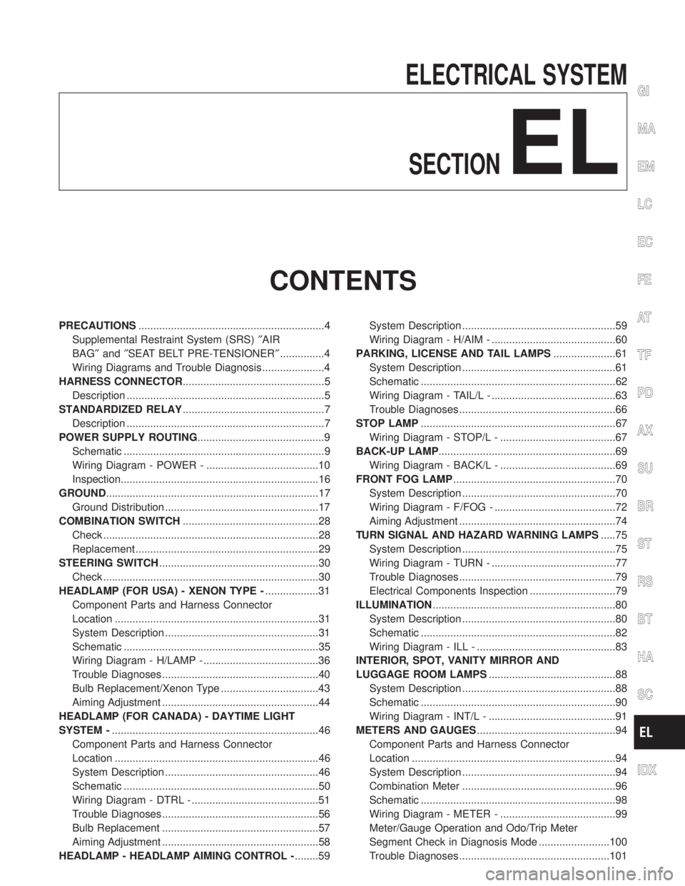
ELECTRICAL SYSTEM
SECTION
EL
CONTENTS
PRECAUTIONS...............................................................4
Supplemental Restraint System (SRS)²AIR
BAG²and²SEAT BELT PRE-TENSIONER²...............4
Wiring Diagrams and Trouble Diagnosis .....................4
HARNESS CONNECTOR................................................5
Description ...................................................................5
STANDARDIZED RELAY................................................7
Description ...................................................................7
POWER SUPPLY ROUTING...........................................9
Schematic ....................................................................9
Wiring Diagram - POWER - ......................................10
Inspection...................................................................16
GROUND........................................................................17
Ground Distribution ....................................................17
COMBINATION SWITCH..............................................28
Check .........................................................................28
Replacement ..............................................................29
STEERING SWITCH......................................................30
Check .........................................................................30
HEADLAMP (FOR USA) - XENON TYPE -..................31
Component Parts and Harness Connector
Location .....................................................................31
System Description ....................................................31
Schematic ..................................................................35
Wiring Diagram - H/LAMP -.......................................36
Trouble Diagnoses.....................................................40
Bulb Replacement/Xenon Type .................................43
Aiming Adjustment .....................................................44
HEADLAMP (FOR CANADA) - DAYTIME LIGHT
SYSTEM -......................................................................46
Component Parts and Harness Connector
Location .....................................................................46
System Description ....................................................46
Schematic ..................................................................50
Wiring Diagram - DTRL - ...........................................51
Trouble Diagnoses.....................................................56
Bulb Replacement .....................................................57
Aiming Adjustment .....................................................58
HEADLAMP - HEADLAMP AIMING CONTROL -........59System Description ....................................................59
Wiring Diagram - H/AIM - ..........................................60
PARKING, LICENSE AND TAIL LAMPS.....................61
System Description ....................................................61
Schematic ..................................................................62
Wiring Diagram - TAIL/L - ..........................................63
Trouble Diagnoses.....................................................66
STOP LAMP..................................................................67
Wiring Diagram - STOP/L - .......................................67
BACK-UP LAMP............................................................69
Wiring Diagram - BACK/L - .......................................69
FRONT FOG LAMP.......................................................70
System Description ....................................................70
Wiring Diagram - F/FOG - .........................................72
Aiming Adjustment .....................................................74
TURN SIGNAL AND HAZARD WARNING LAMPS.....75
System Description ....................................................75
Wiring Diagram - TURN - ..........................................77
Trouble Diagnoses.....................................................79
Electrical Components Inspection .............................79
ILLUMINATION..............................................................80
System Description ....................................................80
Schematic ..................................................................82
Wiring Diagram - ILL - ...............................................83
INTERIOR, SPOT, VANITY MIRROR AND
LUGGAGE ROOM LAMPS...........................................88
System Description ....................................................88
Schematic ..................................................................90
Wiring Diagram - INT/L - ...........................................91
METERS AND GAUGES...............................................94
Component Parts and Harness Connector
Location .....................................................................94
System Description ....................................................94
Combination Meter ....................................................96
Schematic ..................................................................98
Wiring Diagram - METER - .......................................99
Meter/Gauge Operation and Odo/Trip Meter
Segment Check in Diagnosis Mode ........................100
Trouble Diagnoses...................................................101
GI
MA
EM
LC
EC
FE
AT
TF
PD
AX
SU
BR
ST
RS
BT
HA
SC
IDX
Page 1187 of 2395
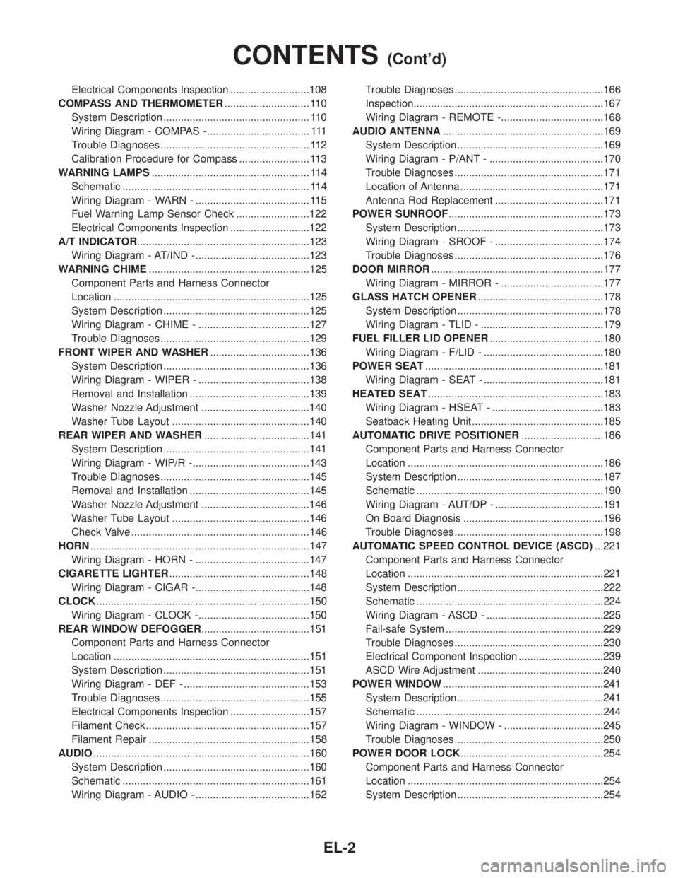
Electrical Components Inspection ...........................108
COMPASS AND THERMOMETER............................. 110
System Description .................................................. 110
Wiring Diagram - COMPAS -................................... 111
Trouble Diagnoses................................................... 112
Calibration Procedure for Compass ........................ 113
WARNING LAMPS...................................................... 114
Schematic ................................................................ 114
Wiring Diagram - WARN - ....................................... 115
Fuel Warning Lamp Sensor Check .........................122
Electrical Components Inspection ...........................122
A/T INDICATOR...........................................................123
Wiring Diagram - AT/IND -.......................................123
WARNING CHIME.......................................................125
Component Parts and Harness Connector
Location ...................................................................125
System Description ..................................................125
Wiring Diagram - CHIME - ......................................127
Trouble Diagnoses...................................................129
FRONT WIPER AND WASHER..................................136
System Description ..................................................136
Wiring Diagram - WIPER - ......................................138
Removal and Installation .........................................139
Washer Nozzle Adjustment .....................................140
Washer Tube Layout ...............................................140
REAR WIPER AND WASHER....................................141
System Description ..................................................141
Wiring Diagram - WIP/R -........................................143
Trouble Diagnoses...................................................145
Removal and Installation .........................................145
Washer Nozzle Adjustment .....................................146
Washer Tube Layout ...............................................146
Check Valve .............................................................146
HORN...........................................................................147
Wiring Diagram - HORN - .......................................147
CIGARETTE LIGHTER................................................148
Wiring Diagram - CIGAR -.......................................148
CLOCK.........................................................................150
Wiring Diagram - CLOCK -......................................150
REAR WINDOW DEFOGGER.....................................151
Component Parts and Harness Connector
Location ...................................................................151
System Description ..................................................151
Wiring Diagram - DEF - ...........................................153
Trouble Diagnoses...................................................155
Electrical Components Inspection ...........................157
Filament Check ........................................................157
Filament Repair .......................................................158
AUDIO..........................................................................160
System Description ..................................................160
Schematic ................................................................161
Wiring Diagram - AUDIO - .......................................162Trouble Diagnoses...................................................166
Inspection.................................................................167
Wiring Diagram - REMOTE -...................................168
AUDIO ANTENNA.......................................................169
System Description ..................................................169
Wiring Diagram - P/ANT - .......................................170
Trouble Diagnoses...................................................171
Location of Antenna .................................................171
Antenna Rod Replacement .....................................171
POWER SUNROOF.....................................................173
System Description ..................................................173
Wiring Diagram - SROOF - .....................................174
Trouble Diagnoses...................................................176
DOOR MIRROR...........................................................177
Wiring Diagram - MIRROR - ...................................177
GLASS HATCH OPENER...........................................178
System Description ..................................................178
Wiring Diagram - TLID - ..........................................179
FUEL FILLER LID OPENER.......................................180
Wiring Diagram - F/LID - .........................................180
POWER SEAT.............................................................181
Wiring Diagram - SEAT - .........................................181
HEATED SEAT............................................................183
Wiring Diagram - HSEAT - ......................................183
Seatback Heating Unit .............................................185
AUTOMATIC DRIVE POSITIONER............................186
Component Parts and Harness Connector
Location ...................................................................186
System Description ..................................................187
Schematic ................................................................190
Wiring Diagram - AUT/DP - .....................................191
On Board Diagnosis ................................................196
Trouble Diagnoses...................................................198
AUTOMATIC SPEED CONTROL DEVICE (ASCD)...221
Component Parts and Harness Connector
Location ...................................................................221
System Description ..................................................222
Schematic ................................................................224
Wiring Diagram - ASCD - ........................................225
Fail-safe System ......................................................229
Trouble Diagnoses...................................................230
Electrical Component Inspection .............................239
ASCD Wire Adjustment ...........................................240
POWER WINDOW.......................................................241
System Description ..................................................241
Schematic ................................................................244
Wiring Diagram - WINDOW - ..................................245
Trouble Diagnoses...................................................250
POWER DOOR LOCK.................................................254
Component Parts and Harness Connector
Location ...................................................................254
System Description ..................................................254
CONTENTS(Cont'd)
EL-2
Page 1188 of 2395
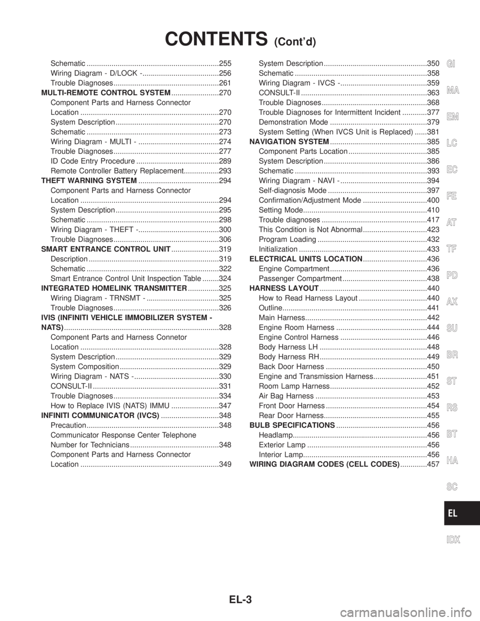
Schematic ................................................................255
Wiring Diagram - D/LOCK -.....................................256
Trouble Diagnoses...................................................261
MULTI-REMOTE CONTROL SYSTEM.......................270
Component Parts and Harness Connector
Location ...................................................................270
System Description ..................................................270
Schematic ................................................................273
Wiring Diagram - MULTI - .......................................274
Trouble Diagnoses...................................................277
ID Code Entry Procedure ........................................289
Remote Controller Battery Replacement.................293
THEFT WARNING SYSTEM.......................................294
Component Parts and Harness Connector
Location ...................................................................294
System Description ..................................................295
Schematic ................................................................298
Wiring Diagram - THEFT -.......................................300
Trouble Diagnoses...................................................306
SMART ENTRANCE CONTROL UNIT.......................319
Description ...............................................................319
Schematic ................................................................322
Smart Entrance Control Unit Inspection Table ........324
INTEGRATED HOMELINK TRANSMITTER...............325
Wiring Diagram - TRNSMT - ...................................325
Trouble Diagnoses...................................................326
IVIS (INFINITI VEHICLE IMMOBILIZER SYSTEM -
NATS)...........................................................................328
Component Parts and Harness Connetor
Location ...................................................................328
System Description ..................................................329
System Composition ................................................329
Wiring Diagram - NATS -.........................................330
CONSULT-II .............................................................331
Trouble Diagnoses...................................................334
How to Replace IVIS (NATS) IMMU .......................347
INFINITI COMMUNICATOR (IVCS)............................348
Precaution ................................................................348
Communicator Response Center Telephone
Number for Technicians ...........................................348
Component Parts and Harness Connector
Location ...................................................................349System Description ..................................................350
Schematic ................................................................358
Wiring Diagram - IVCS -..........................................359
CONSULT-II .............................................................363
Trouble Diagnoses...................................................368
Trouble Diagnoses for Intermittent Incident ............377
Demonstration Mode ...............................................379
System Setting (When IVCS Unit is Replaced) ......381
NAVIGATION SYSTEM...............................................385
Component Parts Location ......................................385
System Description ..................................................386
Schematic ................................................................393
Wiring Diagram - NAVI - ..........................................394
Self-diagnosis Mode ................................................397
Confirmation/Adjustment Mode ...............................400
Setting Mode............................................................410
Trouble diagnoses ...................................................417
This Condition is Not Abnormal ...............................423
Program Loading .....................................................432
Initialization ..............................................................433
ELECTRICAL UNITS LOCATION...............................436
Engine Compartment ...............................................436
Passenger Compartment .........................................438
HARNESS LAYOUT....................................................440
How to Read Harness Layout .................................440
Outline......................................................................441
Main Harness...........................................................442
Engine Room Harness ............................................444
Engine Control Harness ..........................................446
Body Harness LH ....................................................448
Body Harness RH ....................................................449
Back Door Harness .................................................450
Engine and Transmission Harness..........................451
Room Lamp Harness...............................................452
Air Bag Harness ......................................................453
Front Door Harness .................................................454
Rear Door Harness..................................................455
BULB SPECIFICATIONS............................................456
Headlamp.................................................................456
Exterior Lamp ..........................................................456
Interior Lamp............................................................456
WIRING DIAGRAM CODES (CELL CODES).............457GI
MA
EM
LC
EC
FE
AT
TF
PD
AX
SU
BR
ST
RS
BT
HA
SC
IDX
CONTENTS(Cont'd)
EL-3