Page 1123 of 2395
Diagnostic ProcedureNBEC0352
1 INSPECTION START
Do you have CONSULT-II?
YesorNo
Ye s©GO TO 2.
No©GO TO 3.
2 CHECK VACUUM CUT VALVE BYPASS VALVE CIRCUIT
With CONSULT-II
1. Turn ignition switch ªOFFº and then ªONº.
2. Select ªVC/V BYPASS/Vº in ªACTIVE TESTº mode with CONSULT-II.
3. Touch ªON/OFFº on CONSULT-II screen.
SEF014Z
4. Make sure that clicking sound is heard from the vacuum cut valve bypass valve.
OK or NG
OK©GO TO 7.
NG©GO TO 3.
DTC P1490 VACUUM CUT VALVE BYPASS VALVE (CIRCUIT)
Diagnostic Procedure
EC-588
Page 1127 of 2395

On Board Diagnosis LogicNBEC0356Malfunction is detected when vacuum cut valve bypass valve does
not operate properly.
Possible CauseNBEC0593IVacuum cut valve bypass valve
IVacuum cut valve
IBypass hoses for clogging
IEVAP control system pressure sensor and circuit
IEVAP canister vent control valve
IHose between fuel tank and vacuum cut valve clogged
IHose between vacuum cut valve and EVAP canister clogged
IEVAP canister
IEVAP purge port of fuel tank for clogging
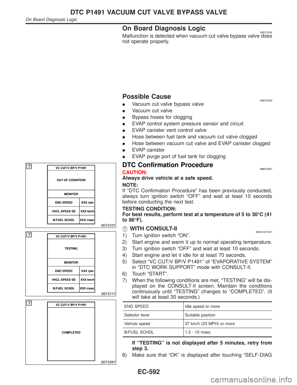
SEF210Y
SEF211Y
SEF239Y
DTC Confirmation ProcedureNBEC0357CAUTION:
Always drive vehicle at a safe speed.
NOTE:
If ªDTC Confirmation Procedureº has been previously conducted,
always turn ignition switch ªOFFº and wait at least 10 seconds
before conducting the next test.
TESTING CONDITION:
For best results, perform test at a temperature of 5 to 30ÉC (41
to 86ÉF).
WITH CONSULT-IINBEC0357S011) Turn ignition switch ªONº.
2) Start engine and warm it up to normal operating temperature.
3) Turn ignition switch ªOFFº and wait at least 10 seconds.
4) Start engine and let it idle for at least 70 seconds.
5) Select ªVC CUT/V BP/V P1491º of ªEVAPORATIVE SYSTEMº
in ªDTC WORK SUPPORTº mode with CONSULT-II.
6) Touch ªSTARTº.
7) When the following conditions are met, ªTESTINGº will be dis-
played on the CONSULT-II screen. Maintain the conditions
continuously until ªTESTINGº changes to ªCOMPLETEDº. (It
will take at least 30 seconds.)
ENG SPEED Idle speed or more
Selector lever Suitable position
Vehicle speed 37 km/h (23 MPH) or more
B/FUEL SCHDL 1.3 - 10 msec
If ªTESTINGº is not displayed after 5 minutes, retry from
step 3.
8) Make sure that ªOKº is displayed after touching ªSELF-DIAG
DTC P1491 VACUUM CUT VALVE BYPASS VALVE
On Board Diagnosis Logic
EC-592
Page 1130 of 2395
Diagnostic ProcedureNBEC0360
1 INSPECTION START
Do you have CONSULT-II?
YesorNo
Ye s©GO TO 2.
No©GO TO 3.
2 CHECK VACUUM CUT VALVE BYPASS VALVE OPERATION
With CONSULT-II
1. Turn ignition switch ªOFFº.
2. Remove vacuum cut valve and vacuum cut valve bypass valve as an assembly.
3. Apply vacuum to port A and check that there is no suction from port B.
4. Apply vacuum to port B and check that there is suction from port A.
5. Blow air in port B and check that there is a resistance to flow out of port A.
6. Turn ignition switch ªONº.
7. Select ªVC/V BYPASS/Vº in ªACTIVE TESTº mode with CONSULT-II and touch ªONº.
8. Blow air in port A and check that air flows freely out of port B.
9. Blow air in port B and check that air flows freely out of port A.
SEF017Z
OK or NG
OK©GO TO 4.
NG©GO TO 5.
GI
MA
EM
LC
FE
AT
TF
PD
AX
SU
BR
ST
RS
BT
HA
SC
EL
IDX
DTC P1491 VACUUM CUT VALVE BYPASS VALVE
Diagnostic Procedure
EC-595
Page 1138 of 2395

Component DescriptionNBEC0361The malfunction information related to A/T (Automatic Transmission) is transferred through the line (circuit)
from TCM (Transmission control module) to ECM. Therefore, be sure to erase the malfunction information such
as DTC not only in TCM (Transmission control module) but also ECM after the A/T related repair.
On Board Diagnosis LogicNBEC0363Malfunction is detected when an incorrect signal from TCM (Trans-
mission control module) is sent to ECM.
Possible CauseNBEC0594IHarness or connectors
[The communication line circuit between ECM and TCM
(Transmission control module) is open or shorted.]
IDead (Weak) battery
ITCM (Transmission control module)
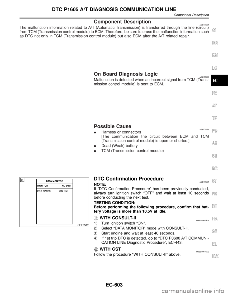
SEF058Y
DTC Confirmation ProcedureNBEC0364NOTE:
If ªDTC Confirmation Procedureº has been previously conducted,
always turn ignition switch ªOFFº and wait at least 10 seconds
before conducting the next test.
TESTING CONDITION:
Before performing the following procedure, confirm that bat-
tery voltage is more than 10.5V at idle.
WITH CONSULT-IINBEC0364S011) Turn ignition switch ªONº.
2) Select ªDATA MONITORº mode with CONSULT-II.
3) Start engine and wait at least 40 seconds.
4) If 1st trip DTC is detected, go to ªDTC P0600 A/T COMMUNI-
CATION LINE Diagnostic Procedureº, EC-443.
WITH GSTNBEC0364S02Follow the procedure ªWITH CONSULT-IIº above.
GI
MA
EM
LC
FE
AT
TF
PD
AX
SU
BR
ST
RS
BT
HA
SC
EL
IDX
DTC P1605 A/T DIAGNOSIS COMMUNICATION LINE
Component Description
EC-603
Page 1139 of 2395

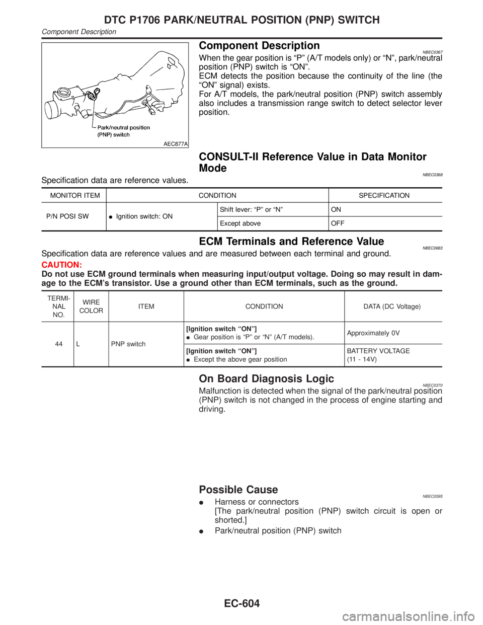
AEC877A
Component DescriptionNBEC0367When the gear position is ªPº (A/T models only) or ªNº, park/neutral
position (PNP) switch is ªONº.
ECM detects the position because the continuity of the line (the
ªONº signal) exists.
For A/T models, the park/neutral position (PNP) switch assembly
also includes a transmission range switch to detect selector lever
position.
CONSULT-II Reference Value in Data Monitor
Mode
NBEC0368Specification data are reference values.
MONITOR ITEM CONDITION SPECIFICATION
P/N POSI SWIIgnition switch: ONShift lever: ªPº or ªNº ON
Except above OFF
ECM Terminals and Reference ValueNBEC0683Specification data are reference values and are measured between each terminal and ground.
CAUTION:
Do not use ECM ground terminals when measuring input/output voltage. Doing so may result in dam-
age to the ECM's transistor. Use a ground other than ECM terminals, such as the ground.
TERMI-
NAL
NO.WIRE
COLORITEM CONDITION DATA (DC Voltage)
44 L PNP switch[Ignition switch ªONº]
IGear position is ªPº or ªNº (A/T models).Approximately 0V
[Ignition switch ªONº]
IExcept the above gear positionBATTERY VOLTAGE
(11 - 14V)
On Board Diagnosis LogicNBEC0370Malfunction is detected when the signal of the park/neutral position
(PNP) switch is not changed in the process of engine starting and
driving.
Possible CauseNBEC0595IHarness or connectors
[The park/neutral position (PNP) switch circuit is open or
shorted.]
IPark/neutral position (PNP) switch
DTC P1706 PARK/NEUTRAL POSITION (PNP) SWITCH
Component Description
EC-604
Page 1140 of 2395

DTC Confirmation ProcedureNBEC0371CAUTION:
Always drive vehicle at a safe speed.
NOTE:
If ªDTC Confirmation Procedureº has been previously conducted,
always turn ignition switch ªOFFº and wait at least 10 seconds
before conducting the next test.
SEF212Y
SEF213Y
WITH CONSULT-IINBEC0371S011) Turn ignition switch ªONº.
2) Select ªP/N POSI SWº in ªDATA MONITORº mode with CON-
SULT-II. Then check the ªP/N POSI SWº signal under the fol-
lowing conditions.
Position (Selector lever) Known-good signal
ªNº and ªPº position ON
Except the above position OFF
If NG, go to ªDiagnostic Procedureº, EC-608.
If OK, go to following step.
3) Select ªDATA MONITORº mode with CONSULT-II.
4) Start engine and warm it up to normal operating temperature.
5) Maintain the following conditions for at least 60 consecutive
seconds.
ENG SPEED 1,500 - 2,500 rpm
COOLAN TEMP/S More than 70ÉC (158ÉF)
B/FUEL SCHDL 3.6 - 12 msec
VHCL SPEED SE 70 - 100 km/h (43 - 62 MPH)
Selector lever Suitable position
6) If 1st trip DTC is detected, go to ªDiagnostic Procedureº,
EC-608.
GI
MA
EM
LC
FE
AT
TF
PD
AX
SU
BR
ST
RS
BT
HA
SC
EL
IDX
DTC P1706 PARK/NEUTRAL POSITION (PNP) SWITCH
DTC Confirmation Procedure
EC-605
Page 1174 of 2395

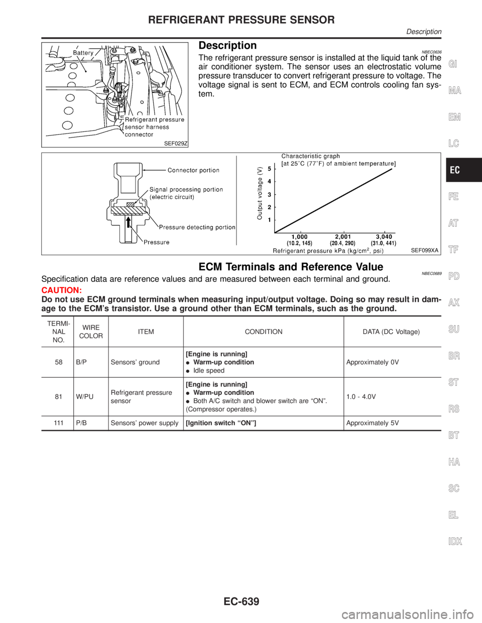
SEF029Z
DescriptionNBEC0636The refrigerant pressure sensor is installed at the liquid tank of the
air conditioner system. The sensor uses an electrostatic volume
pressure transducer to convert refrigerant pressure to voltage. The
voltage signal is sent to ECM, and ECM controls cooling fan sys-
tem.
SEF099XA
ECM Terminals and Reference ValueNBEC0689Specification data are reference values and are measured between each terminal and ground.
CAUTION:
Do not use ECM ground terminals when measuring input/output voltage. Doing so may result in dam-
age to the ECM's transistor. Use a ground other than ECM terminals, such as the ground.
TERMI-
NAL
NO.WIRE
COLORITEM CONDITION DATA (DC Voltage)
58 B/P Sensors' ground[Engine is running]
IWarm-up condition
IIdle speedApproximately 0V
81 W/PURefrigerant pressure
sensor[Engine is running]
IWarm-up condition
IBoth A/C switch and blower switch are ªONº.
(Compressor operates.)1.0 - 4.0V
111 P/B Sensors' power supply[Ignition switch ªONº]Approximately 5V
GI
MA
EM
LC
FE
AT
TF
PD
AX
SU
BR
ST
RS
BT
HA
SC
EL
IDX
REFRIGERANT PRESSURE SENSOR
Description
EC-639
Page 1178 of 2395
ECM Terminals and Reference ValueNBEC0690Specification data are reference values and are measured between each terminal and ground.
CAUTION:
Do not use ECM ground terminals when measuring input/output voltage. Doing so may result in dam-
age to the ECM's transistor. Use a ground other than ECM terminals, such as the ground.
TERMI-
NAL
NO.WIRE
COLORITEM CONDITION DATA (DC Voltage)
52 PU Electrical load signal[Engine is running]
IRear window defogger: ON
IHi-beam headlamp: ONBATTERY VOLTAGE
(11 - 14V)
[Engine is running]
IElectrical load: OFF0V
GI
MA
EM
LC
FE
AT
TF
PD
AX
SU
BR
ST
RS
BT
HA
SC
EL
IDX
ELECTRICAL LOAD SIGNAL
ECM Terminals and Reference Value
EC-643