Page 1587 of 2395

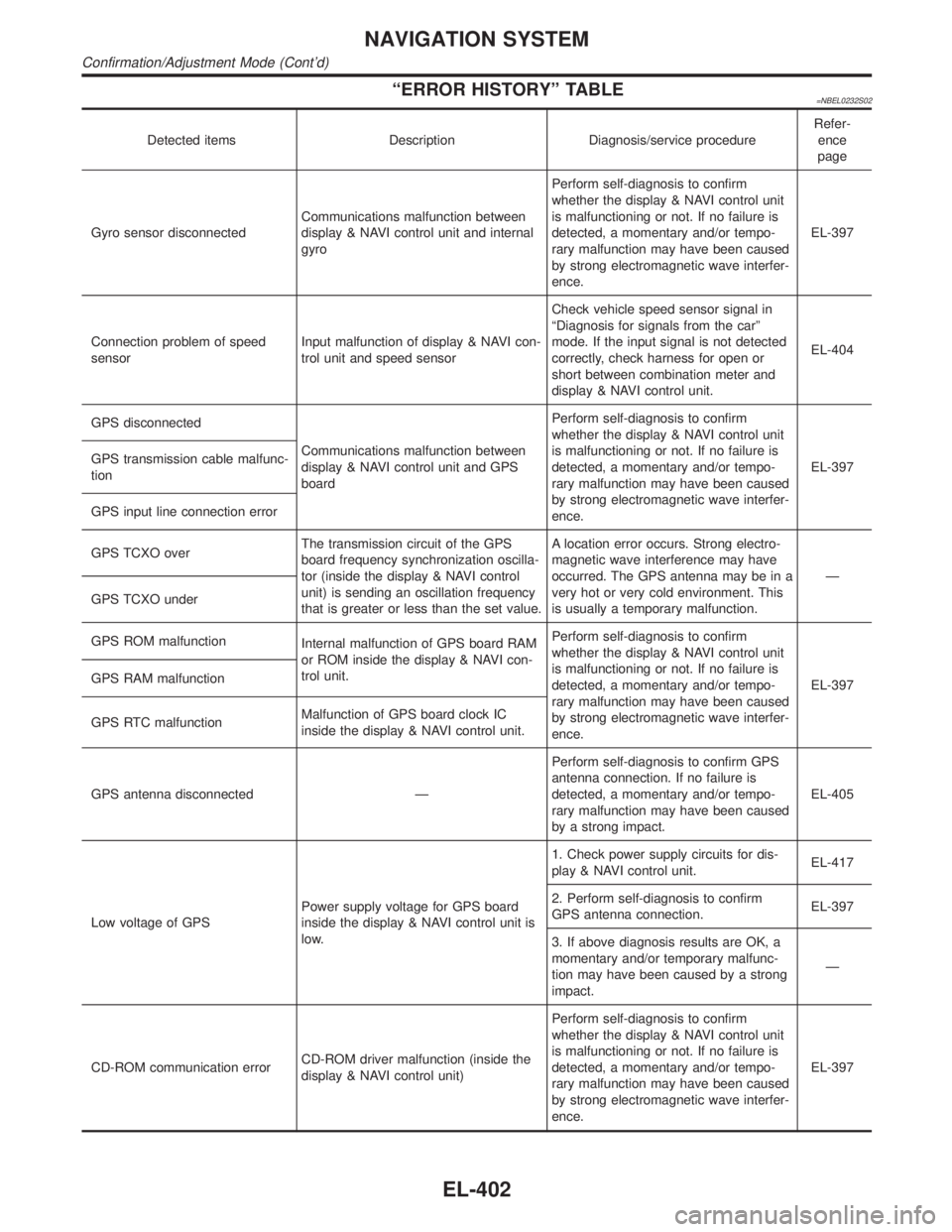
ªERROR HISTORYº TABLE=NBEL0232S02
Detected items Description Diagnosis/service procedureRefer-
ence
page
Gyro sensor disconnectedCommunications malfunction between
display & NAVI control unit and internal
gyroPerform self-diagnosis to confirm
whether the display & NAVI control unit
is malfunctioning or not. If no failure is
detected, a momentary and/or tempo-
rary malfunction may have been caused
by strong electromagnetic wave interfer-
ence.EL-397
Connection problem of speed
sensorInput malfunction of display & NAVI con-
trol unit and speed sensorCheck vehicle speed sensor signal in
ªDiagnosis for signals from the carº
mode. If the input signal is not detected
correctly, check harness for open or
short between combination meter and
display & NAVI control unit.EL-404
GPS disconnected
Communications malfunction between
display & NAVI control unit and GPS
boardPerform self-diagnosis to confirm
whether the display & NAVI control unit
is malfunctioning or not. If no failure is
detected, a momentary and/or tempo-
rary malfunction may have been caused
by strong electromagnetic wave interfer-
ence.EL-397 GPS transmission cable malfunc-
tion
GPS input line connection error
GPS TCXO overThe transmission circuit of the GPS
board frequency synchronization oscilla-
tor (inside the display & NAVI control
unit) is sending an oscillation frequency
that is greater or less than the set value.A location error occurs. Strong electro-
magnetic wave interference may have
occurred. The GPS antenna may be in a
very hot or very cold environment. This
is usually a temporary malfunction.Ð
GPS TCXO under
GPS ROM malfunction
Internal malfunction of GPS board RAM
or ROM inside the display & NAVI con-
trol unit.Perform self-diagnosis to confirm
whether the display & NAVI control unit
is malfunctioning or not. If no failure is
detected, a momentary and/or tempo-
rary malfunction may have been caused
by strong electromagnetic wave interfer-
ence.EL-397 GPS RAM malfunction
GPS RTC malfunctionMalfunction of GPS board clock IC
inside the display & NAVI control unit.
GPS antenna disconnected ÐPerform self-diagnosis to confirm GPS
antenna connection. If no failure is
detected, a momentary and/or tempo-
rary malfunction may have been caused
by a strong impact.EL-405
Low voltage of GPSPower supply voltage for GPS board
inside the display & NAVI control unit is
low.1. Check power supply circuits for dis-
play & NAVI control unit.EL-417
2. Perform self-diagnosis to confirm
GPS antenna connection.EL-397
3. If above diagnosis results are OK, a
momentary and/or temporary malfunc-
tion may have been caused by a strong
impact.Ð
CD-ROM communication errorCD-ROM driver malfunction (inside the
display & NAVI control unit)Perform self-diagnosis to confirm
whether the display & NAVI control unit
is malfunctioning or not. If no failure is
detected, a momentary and/or tempo-
rary malfunction may have been caused
by strong electromagnetic wave interfer-
ence.EL-397
NAVIGATION SYSTEM
Confirmation/Adjustment Mode (Cont'd)
EL-402
Page 1589 of 2395

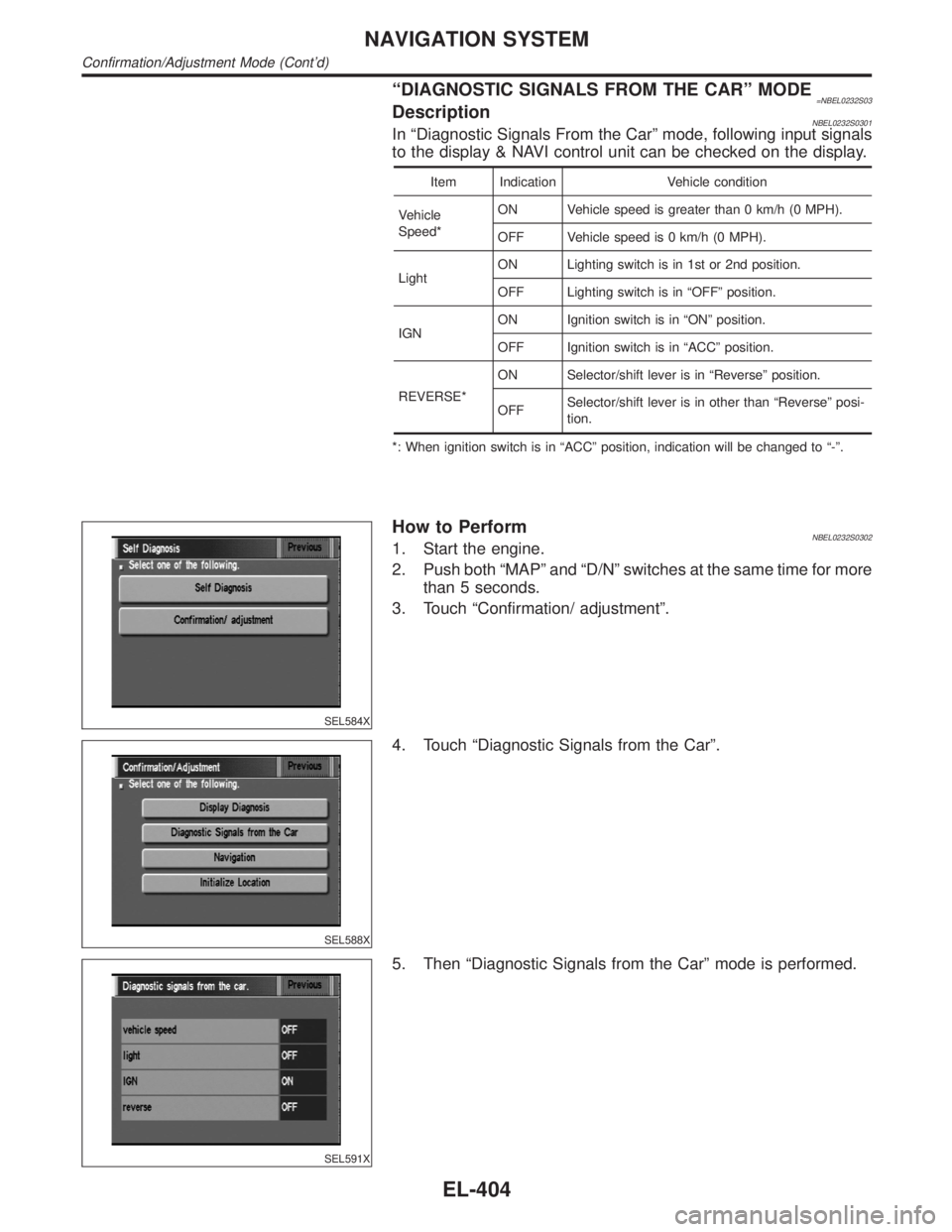
ªDIAGNOSTIC SIGNALS FROM THE CARº MODE=NBEL0232S03DescriptionNBEL0232S0301In ªDiagnostic Signals From the Carº mode, following input signals
to the display & NAVI control unit can be checked on the display.
Item Indication Vehicle condition
Vehicle
Speed*ON Vehicle speed is greater than 0 km/h (0 MPH).
OFF Vehicle speed is 0 km/h (0 MPH).
LightON Lighting switch is in 1st or 2nd position.
OFF Lighting switch is in ªOFFº position.
IGNON Ignition switch is in ªONº position.
OFF Ignition switch is in ªACCº position.
REVERSE*ON Selector/shift lever is in ªReverseº position.
OFFSelector/shift lever is in other than ªReverseº posi-
tion.
*: When ignition switch is in ªACCº position, indication will be changed to ª-º.
SEL584X
How to PerformNBEL0232S03021. Start the engine.
2. Push both ªMAPº and ªD/Nº switches at the same time for more
than 5 seconds.
3. Touch ªConfirmation/ adjustmentº.
SEL588X
4. Touch ªDiagnostic Signals from the Carº.
SEL591X
5. Then ªDiagnostic Signals from the Carº mode is performed.
NAVIGATION SYSTEM
Confirmation/Adjustment Mode (Cont'd)
EL-404
Page 1595 of 2395

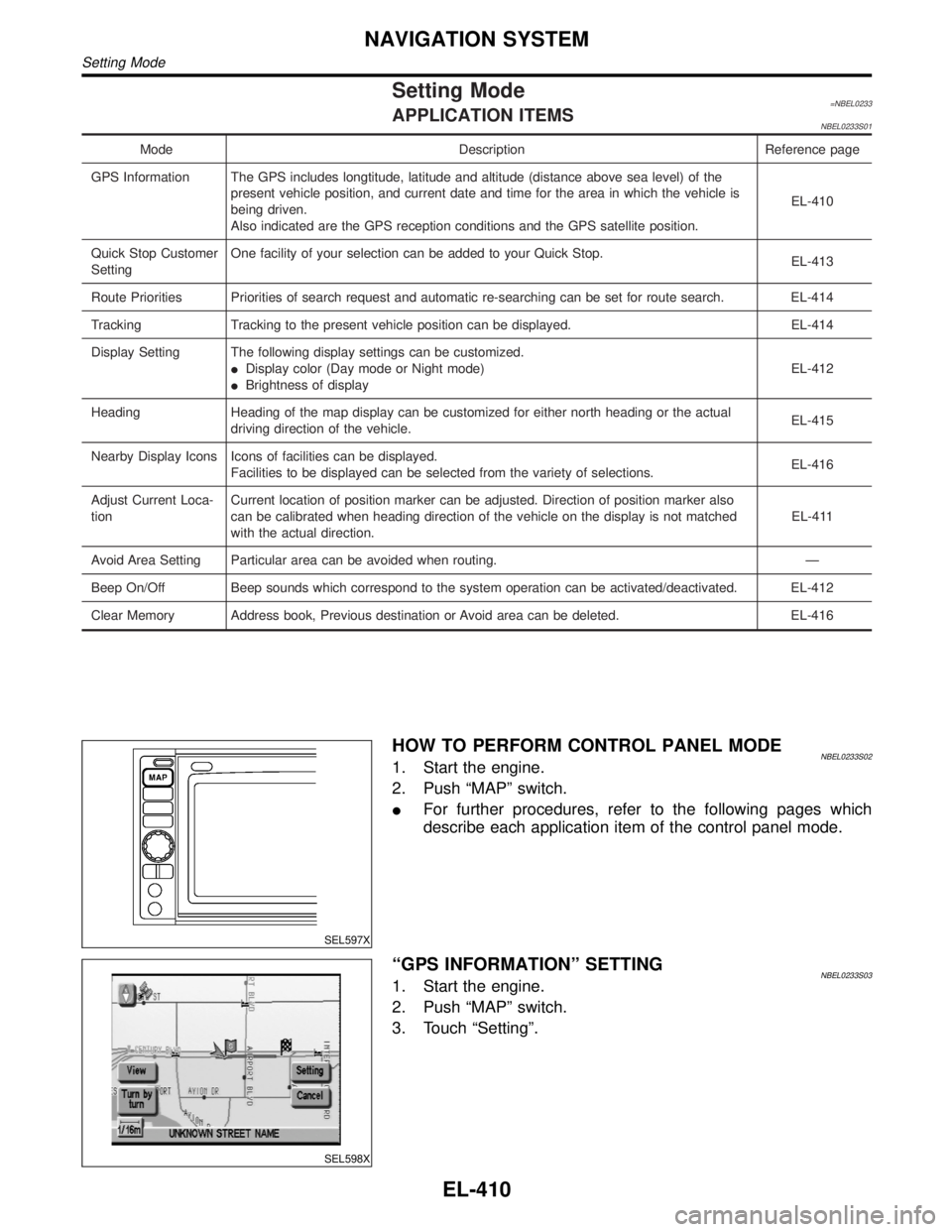
Setting Mode=NBEL0233APPLICATION ITEMSNBEL0233S01
Mode Description Reference page
GPS Information The GPS includes longtitude, latitude and altitude (distance above sea level) of the
present vehicle position, and current date and time for the area in which the vehicle is
being driven.
Also indicated are the GPS reception conditions and the GPS satellite position.EL-410
Quick Stop Customer
SettingOne facility of your selection can be added to your Quick Stop.
EL-413
Route Priorities Priorities of search request and automatic re-searching can be set for route search. EL-414
Tracking Tracking to the present vehicle position can be displayed. EL-414
Display Setting The following display settings can be customized.
IDisplay color (Day mode or Night mode)
IBrightness of displayEL-412
Heading Heading of the map display can be customized for either north heading or the actual
driving direction of the vehicle.EL-415
Nearby Display Icons Icons of facilities can be displayed.
Facilities to be displayed can be selected from the variety of selections.EL-416
Adjust Current Loca-
tionCurrent location of position marker can be adjusted. Direction of position marker also
can be calibrated when heading direction of the vehicle on the display is not matched
with the actual direction.EL-411
Avoid Area Setting Particular area can be avoided when routing. Ð
Beep On/Off Beep sounds which correspond to the system operation can be activated/deactivated. EL-412
Clear Memory Address book, Previous destination or Avoid area can be deleted. EL-416
SEL597X
HOW TO PERFORM CONTROL PANEL MODENBEL0233S021. Start the engine.
2. Push ªMAPº switch.
IFor further procedures, refer to the following pages which
describe each application item of the control panel mode.
SEL598X
ªGPS INFORMATIONº SETTINGNBEL0233S031. Start the engine.
2. Push ªMAPº switch.
3. Touch ªSettingº.
NAVIGATION SYSTEM
Setting Mode
EL-410
Page 1597 of 2395
SEL602X
6. Touch ªºorªº to calibrate the heading direction. (Arrow
marks will rotate corresponding to the calibration key.)
7. Touch ªSetº. Then the vehicle mark will be matched to the
arrow mark.
8. Display will show ªHeading direction has been calibratedº and
then go back to the current location map.
SEL598X
BEEP ON/OFF SETTINGNBEL0233S051. Start the engine.
2. Push ªMAPº switch.
3. Touch ªSettingº.
4. Touch ªSystem Settingº.
SEL603X
5. Touch ªBeep on/offº.
SEL604X
6. Touch ªOnº or ªOffº icon.
IIf you want the beep sound, select ªONº.
IIf you do not want the beep sound, select ªOFFº.
7. Push ªMAPº switch, then the display will go back to the current
location map.
DISPLAY SETTINGNBEL0233S06DescriptionNBEL0233S0601The following display setting can be changed in this mode.
IDimmer operation (when lighting switch is turned on.)
IDisplay color (Day mode or Night mode)
IBrightness of display
NAVIGATION SYSTEM
Setting Mode (Cont'd)
EL-412
Page 1599 of 2395
SEL606X
6. Select from the itemized list.
SEL598X
ªROUTE PRIORITIESº MODENBEL0233S101. Start the engine.
2. Push the ªMAPº switch.
3. Touch ªSettingº.
4. Touch ªSystem Settingº.
SEL600X
5. Touch ªRoute Prioritiesº.
SEL607X
6. Select from the itemized list.
SEL598X
ªTRACKINGº MODENBEL0233S111. Start the engine.
2. Push the ªMAPº switch.
3. Touch ªSettingº.
4. Touch ªSystem Settingº.
NAVIGATION SYSTEM
Setting Mode (Cont'd)
EL-414
Page 1600 of 2395
SEL600X
5. Touch ªTrackingº.
SEL608X
6. Touch the ªOnº or ªOffº icon.
IIf you don't need a trail on the map, select ªOffº.
IIf you need a trail on the map, select ªOnº.
7. Push the ªMAPº switch to return the display to the current
location map.
NOTE:
When a trail display is turned OFF, trail data is erased from the
memory.
SEL598X
ªHEADINGº MODENBEL0233S121. Start the engine.
2. Push the ªMAPº switch.
3. Touch ªSettingº.
4. Touch ªSystem Settingº.
SEL601X
5. Touch ªHeadingº.
SEL609X
6. Touch the ªHeading upº or ªNorth upº icon.
ITo display North up, select ªNorth upº.
ITo display the car heading up, select ªHeading upº.
7. Push the ªMAPº switch, then the display will go back to the
current location map.
GI
MA
EM
LC
EC
FE
AT
TF
PD
AX
SU
BR
ST
RS
BT
HA
SC
IDX
NAVIGATION SYSTEM
Setting Mode (Cont'd)
EL-415
Page 1601 of 2395
SEL598X
ªNEARBY DISPLAY ICONSº MODENBEL0233S131. Start the engine.
2. Push the ªMAPº switch.
3. Touch ªSettingº.
4. Touch ªSystem Settingº.
SEL601X
5. Touch ªNearby Display Iconsº.
SEL610X
6. Select and touch the itemized list.
7. Push the ªMAPº switch to return the display to the current
location map.
SEL598X
ªCLEAR MEMORYº MODENBEL0233S141. Start the engine.
2. Push the ªMAPº switch.
3. Touch ªSettingº.
4. Touch ªSystem Settingº.
SEL600X
5. Touch ªClear Memoryº.
NAVIGATION SYSTEM
Setting Mode (Cont'd)
EL-416
Page 1602 of 2395

SEL611X
6. To delete all the stored places in the ªAddress Bookº, ªAvoid
Areaº and ªPrevious Dest.º, select ªYesº.
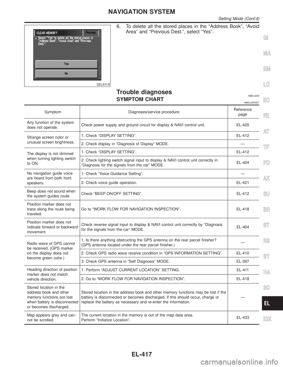
Trouble diagnosesNBEL0234SYMPTOM CHARTNBEL0234S01
Symptom Diagnoses/service procedureReference
page
Any function of the system
does not operate.Check power supply and ground circuit for display & NAVI control unit. EL-420
Strange screen color or
unusual screen brightness.1. Check ªDISPLAY SETTINGº. EL-412
2. Check display in ªDiagnosis of Displayº MODE. Ð
The display is not dimmed
when turning lighting switch
to ON.1. Check ªDISPLAY SETTINGº. EL-412
2. Check lighting switch signal input to display & NAVI control unit correctly in
ªDiagnosis for the signals from the carº MODE.EL-404
No navigation guide voice
are heard from both front
speakers.1. Check ªVoice Guidance Settingº. Ð
2. Check voice guide operation. EL-421
Beep does not sound when
the system guides route.Check ªBEEP ON/OFF SETTINGº. EL-412
Position marker does not
trace along the route being
traveled.Go to ªWORK FLOW FOR NAVIGATION INSPECTIONº. EL-418
Position marker does not
indicate forward or backward
movement.Check reverse signal input to display & NAVI control unit correctly by ªDiagnosis
for the signals from the carº MODE.EL-404
Radio wave of GPS cannot
be received. (GPS marker
on the display does not
become green color.)1. Is there anything obstructing the GPS antenna on the rear parcel finisher?
(GPS antenna located under the rear parcel finisher.)Ð
2. Check GPS radio wave receive condition in ªGPS INFORMATION SETTINGº. EL-410
3. Check GPS antenna in ªSelf Diagnosisº MODE. EL-397
Heading direction of position
marker does not match
vehicle direction.1. Perform ªADJUST CURRENT LOCATIONº SETTING. EL-411
2. Go to ªWORK FLOW FOR NAVIGATION INSPECTIONº. EL-418
Stored location in the
address book and other
memory functions are lost
when battery is disconnected
or becomes discharged.Stored location in the address book and other memory functions may be lost if the
battery is disconnected or becomes discharged. If this should occur, charge or
replace the battery as necessary and re-enter the information.Ð
Map appears grey and can-
not be scrolled.The current location in the memory is out of the map data area.
Perform ªInitialize Locationº.EL-433
GI
MA
EM
LC
EC
FE
AT
TF
PD
AX
SU
BR
ST
RS
BT
HA
SC
IDX
NAVIGATION SYSTEM
Setting Mode (Cont'd)
EL-417