Page 2272 of 2395

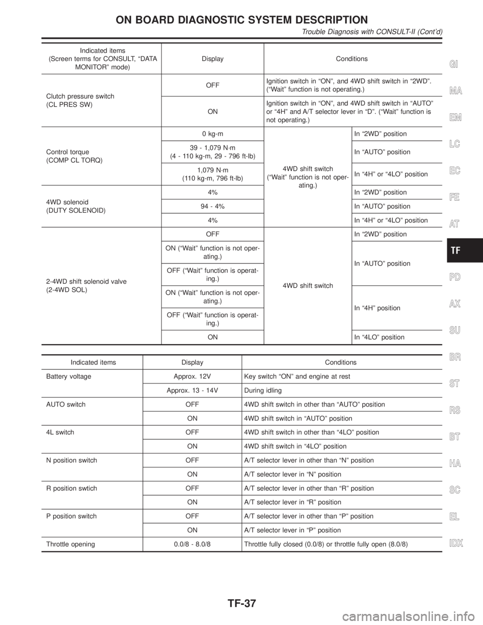
Indicated items
(Screen terms for CONSULT, ªDATA
MONITORº mode)Display Conditions
Clutch pressure switch
(CL PRES SW)OFFIgnition switch in ªONº, and 4WD shift switch in ª2WDº.
(ªWaitº function is not operating.)
ONIgnition switch in ªONº, and 4WD shift switch in ªAUTOº
or ª4Hº and A/T selector lever in ªDº. (ªWaitº function is
not operating.)
Control torque
(COMP CL TORQ)0 kg-m
4WD shift switch
(ªWaitº function is not oper-
ating.)In ª2WDº position
39 - 1,079 N´m
(4 - 110 kg-m, 29 - 796 ft-lb)In ªAUTOº position
1,079 N´m
(110 kg-m, 796 ft-lb)In ª4Hº or ª4LOº position
4WD solenoid
(DUTY SOLENOID)4% In ª2WDº position
94 - 4% In ªAUTOº position
4% In ª4Hº or ª4LOº position
2-4WD shift solenoid valve
(2-4WD SOL)OFF
4WD shift switchIn ª2WDº position
ON (ªWaitº function is not oper-
ating.)
In ªAUTOº position
OFF (ªWaitº function is operat-
ing.)
ON (ªWaitº function is not oper-
ating.)
In ª4Hº position
OFF (ªWaitº function is operat-
ing.)
ON In ª4LOº position
Indicated items Display Conditions
Battery voltage Approx. 12V Key switch ªONº and engine at rest
Approx. 13 - 14V During idling
AUTO switch OFF 4WD shift switch in other than ªAUTOº position
ON 4WD shift switch in ªAUTOº position
4L switch OFF 4WD shift switch in other than ª4LOº position
ON 4WD shift switch in ª4LOº position
N position switch OFF A/T selector lever in other than ªNº position
ON A/T selector lever in ªNº position
R position swtich OFF A/T selector lever in other than ªRº position
ON A/T selector lever in ªRº position
P position switch OFF A/T selector lever in other than ªPº position
ON A/T selector lever in ªPº position
Throttle opening 0.0/8 - 8.0/8 Throttle fully closed (0.0/8) or throttle fully open (8.0/8)
GI
MA
EM
LC
EC
FE
AT
PD
AX
SU
BR
ST
RS
BT
HA
SC
EL
IDX
ON BOARD DIAGNOSTIC SYSTEM DESCRIPTION
Trouble Diagnosis with CONSULT-II (Cont'd)
TF-37
Page 2276 of 2395

IntroductionNBTF0013DESCRIPTIONNBTF0013S01When a malfunction (indicated by the 4WD warning lamp illumination) occurs, collect information first from the
customer about how the malfunction occurs. Then, proceed with the diagnosis presuming it is the cause. Also
inspect the electrical system, paying close attention to other possibilities such as fluid level and leaks.
All-mode 4WD transfer is controlled by transfer control unit and sensors.
If a malfunction occurs in the all-mode 4WD system, the 4WD warning lamp lights up to inform of the system
malfunction. There are two ways to identify the cause of the malfunction.
1) Performing the self-diagnosis. (The 4WD warning lamp will indicate what kind of malfunction has occurred
by flickering.)
2) Performing diagnosis using CONSULT-II.
DIAGNOSTIC WORKSHEETNBTF0013S02Information from CustomerNBTF0013S0201KEY POINTS
WHAT..... Vehicle model
WHEN..... Date, Frequencies
WHERE..... Road conditions
HOW..... Operating conditions, Symptoms
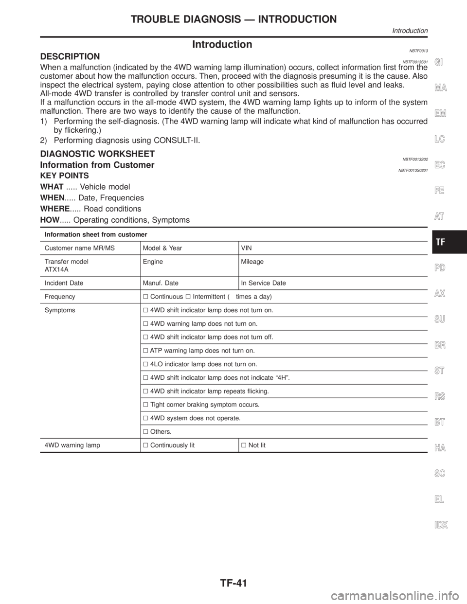
Information sheet from customer
Customer name MR/MS Model & Year VIN
Transfer model
ATX14AEngine Mileage
Incident Date Manuf. Date In Service Date
FrequencylContinuouslIntermittent ( times a day)
Symptomsl4WD shift indicator lamp does not turn on.
l4WD warning lamp does not turn on.
l4WD shift indicator lamp does not turn off.
lATP warning lamp does not turn on.
l4LO indicator lamp does not turn on.
l4WD shift indicator lamp does not indicate ª4Hº.
l4WD shift indicator lamp repeats flicking.
lTight corner braking symptom occurs.
l4WD system does not operate.
lOthers.
4WD warning lamplContinuously litlNot lit
GI
MA
EM
LC
EC
FE
AT
PD
AX
SU
BR
ST
RS
BT
HA
SC
EL
IDX
TROUBLE DIAGNOSIS Ð INTRODUCTION
Introduction
TF-41
Page 2290 of 2395

SMT772D
TRANSFER CONTROL UNIT INSPECTION TABLENBTF0018S02(Data are reference values.)
Terminal
No.Item Condition Judgement standard
12-4WD shift solenoid
valve
&
4WD shift switch is set to ª2WDº
position.Less than 1V
4WD shift switch is set to any posi-
tion other than ª2WDº.Battery voltage
24WD shift indicator lamp
(2WD)
Lamp lights while system is operating
properly.Less than 1V
&
2WD indicator lamp does not come
on.Battery voltage
3 Ground Ð Ð
4Transfer shift relay
(High)While actuator is operating
(4H,4LO)Battery voltage
Actuator does not operate. Less than 1V
5 4WD warning lampLamp comes ON. (when engine is
stopped.)
(Fail-safe condition appears on
display, engine is stopped, actuator
position detection switch is
inoperative, oil temperature is too
high and/or tires of different size are
installed.)Less than 1V
Except above Battery voltage
6 Ground Ð Ð Ð
7 PNP switch (R position)
&
A/T selector lever is set to ªreverseº
position.Battery voltage
A/T selector lever is set to any posi-
tion other than ªreverseº.Less than 1V
8ÐÐÐÐ
GI
MA
EM
LC
EC
FE
AT
PD
AX
SU
BR
ST
RS
BT
HA
SC
EL
IDX
TROUBLE DIAGNOSIS Ð GENERAL DESCRIPTION
Transfer Control Unit Terminals and Reference Value (Cont'd)
TF-55
Page 2298 of 2395

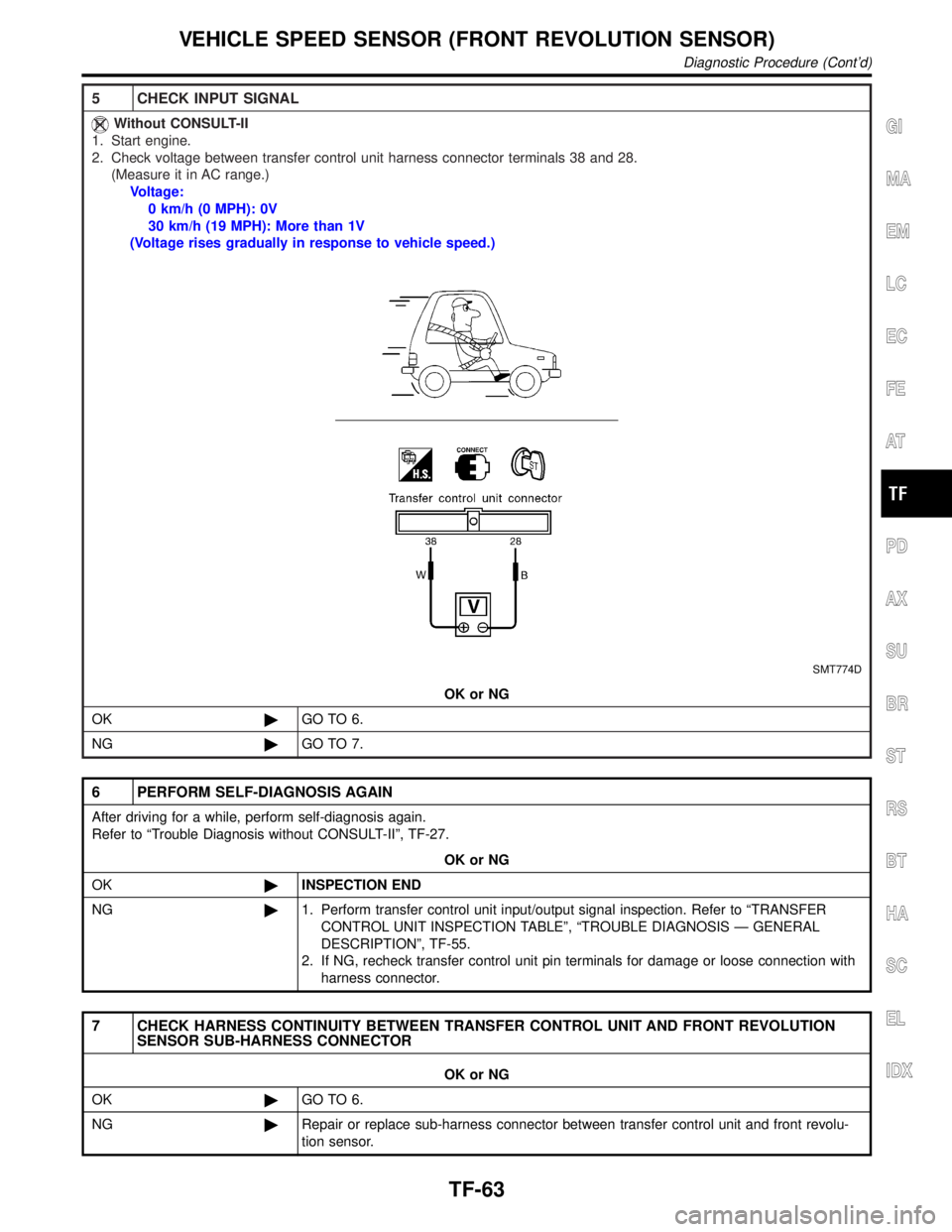
5 CHECK INPUT SIGNAL
Without CONSULT-II
1. Start engine.
2. Check voltage between transfer control unit harness connector terminals 38 and 28.
(Measure it in AC range.)
Voltage:
0 km/h (0 MPH): 0V
30 km/h (19 MPH): More than 1V
(Voltage rises gradually in response to vehicle speed.)
SMT774D
OK or NG
OK©GO TO 6.
NG©GO TO 7.
6 PERFORM SELF-DIAGNOSIS AGAIN
After driving for a while, perform self-diagnosis again.
Refer to ªTrouble Diagnosis without CONSULT-IIº, TF-27.
OK or NG
OK©INSPECTION END
NG©1. Perform transfer control unit input/output signal inspection. Refer to ªTRANSFER
CONTROL UNIT INSPECTION TABLEº, ªTROUBLE DIAGNOSIS Ð GENERAL
DESCRIPTIONº, TF-55.
2. If NG, recheck transfer control unit pin terminals for damage or loose connection with
harness connector.
7 CHECK HARNESS CONTINUITY BETWEEN TRANSFER CONTROL UNIT AND FRONT REVOLUTION
SENSOR SUB-HARNESS CONNECTOR
OK or NG
OK©GO TO 6.
NG©Repair or replace sub-harness connector between transfer control unit and front revolu-
tion sensor.
GI
MA
EM
LC
EC
FE
AT
PD
AX
SU
BR
ST
RS
BT
HA
SC
EL
IDX
VEHICLE SPEED SENSOR (FRONT REVOLUTION SENSOR)
Diagnostic Procedure (Cont'd)
TF-63
Page 2309 of 2395
4 CHECK INPUT SIGNAL
SMT784D
With CONSULT-II
1. Start engine.
2. Select ªECU INPUT SIGNALSº in Data Monitor.
3. Read out the value of ªFLUID TEMP SEº.
Voltage:
20ÉC (68ÉF): Approx. 1.5V
80ÉC (176ÉF): Approx. 0.5V
SMT974D
OK or NG
OK©GO TO 6.
NG©Check the following.
IContinuity between transfer control unit and transfer terminal cord assembly sub-har-
ness connector
TRANSFER FLUID TEMPERATURE SENSOR
Diagnostic Procedure (Cont'd)
TF-74
Page 2324 of 2395
Diagnostic ProcedureNBTF0064
1 SHIFT ACTUATOR
Refer to ªActuator & Actuator Position Switchº, ªCOMPONENT INSPECTIONº, TF-115.
OK or NG
OK©GO TO 3.
NG©GO TO 2.
2 CHECK POWER SOURCE
SMT825DA
1. Disconnect transfer control device terminal.
2. Turn ignition switch to ªONº. (Do not start engine.)
3. Check voltage between transfer control device harness connector 3 (or 4) and body ground while 4WD shift switch is
set from 4H to 4LO (or from 4LO to 4H).
Voltage: Battery voltage
OK or NG
OK©Repair or replace actuator.
NG©1. Recheck the following.
IContinuity between ignition switch and transfer HI & LOW relays
IIgnition switch and No. 3 fuse (20A)
IContinuity between transfer shift HI & LOW relays and transfer control device
2. If NG, repair or replace damaged part.
3 CHECK INPUT SIGNAL
WITH CONSULT-II©GO TO 4.
WITHOUT CONSULT-II©GO TO 5.
GI
MA
EM
LC
EC
FE
AT
PD
AX
SU
BR
ST
RS
BT
HA
SC
EL
IDX
SHIFT ACTUATOR
Diagnostic Procedure
TF-89
Page 2326 of 2395

5 CHECK INPUT SIGNAL
Without CONSULT-II
1. Start engine (idling).
2. Check voltage between transfer control unit harness connector terminal 33 (or 42) and body ground while 4WD shift
switch is set from 4H to 4LO (or from 4LO to 4H).
SMT828D
3. Result
MTBL0202
OK or NG
OK©GO TO 7.
NG©GO TO 6.
6 CHECK HARNESS CONTINUITY BETWEEN TRANSFER CONTROL UNIT AND TRANSFER CONTROL
DEVICE
OK or NG
OK©GO TO 7.
NG©Repair and replace harness connector between transfer control unit and transfer control
device.
7 PERFORM SELF-DIAGNOSIS AGAIN
After driving for a while, perform self-diagnosis again.
Refer to ªTrouble Diagnosis without CONSULT-IIº, TF-27.
OK or NG
OK©INSPECTION END
NG©1. Perform transfer control unit/output signal inspection. Refer to ªTRANSFER CON-
TROL UNIT INSPECTION TABLEº, ªTROUBLE DIAGNOSIS Ð GENERAL
DESCRIPTIONº, TF-55.
2. If NG, recheck transfer control unit pin terminals for damage or loose connection with
harness connector.
GI
MA
EM
LC
EC
FE
AT
PD
AX
SU
BR
ST
RS
BT
HA
SC
EL
IDX
SHIFT ACTUATOR
Diagnostic Procedure (Cont'd)
TF-91
Page 2328 of 2395

5 CHECK INPUT SIGNAL
Without CONSULT-II
1. Start engine (idling).
2. Check voltage transfer control unit harness connector terminal 27 (or 44) and body ground while 4WD shift switch is
set from 4H to 4LO (or from 4LO to 4H).
SMT830D
3. Result
MTBL0203
OK or NG
OK©GO TO 7.
NG©GO TO 6.
6 CHECK HARNESS CONTINUITY BETWEEN TRANSFER CONTROL UNIT AND TRANSFER CONTROL
DEVICE
OK or NG
OK©GO TO 7.
NG©Repair and replace harness connector between transfer control unit and transfer control
device.
7 PERFORM SELF-DIAGNOSIS AGAIN
After driving for a while, perform self-diagnosis again.
Refer to ªTrouble Diagnosis without CONSULT-IIº, TF-27.
OK or NG
OK©INSPECTION END
NG©1. Perform transfer control unit/output signal inspection. Refer to ªTRANSFER CON-
TROL UNIT INSPECTION TABLEº, ªTROUBLE DIAGNOSIS Ð GENERAL
DESCRIPTIONº, TF-55.
2. If NG, recheck transfer control unit pin terminals for damage or loose connection with
harness connector.
GI
MA
EM
LC
EC
FE
AT
PD
AX
SU
BR
ST
RS
BT
HA
SC
EL
IDX
SHIFT ACTUATOR POSITION SWITCH
Diagnostic Procedure (Cont'd)
TF-93