2001 INFINITI QX4 Engine control
[x] Cancel search: Engine controlPage 1287 of 2395

SYMPTOM CHARTNBEL0201S02Symptom Chart 1 (Malfunction is Indicated in
Diagnosis Mode)
NBEL0201S0201
Symptom Possible causes Repair order
Odo/trip meter indicate(s)
malfunction in Diagnosis
mode.Unified meter control unit Replace unified meter control unit.
Multiple meter/gauge indi-
cate malfunction in Diagno-
sis mode.
One of speedometer/
tachometer/fuel gauge/
water temp. gauge indi-
cates malfunction in Diag-
nosis mode.1. Meter/Gauge
2. Unified meter control unit1. Check resistance of meter/gauge indicating malfunc-
tion. If the resistance is NG, replace the meter/
gauge. Refer to ªMETER/GAUGE RESISTANCE
CHECKº, EL-108.
2. If the resistance of meter/gauge is OK, replace uni-
fied meter control unit.
Symptom Chart 2 (No Malfunction is Indicated in
Diagnosis Mode)
NBEL0201S0202
Symptom Possible causes Repair order
One of speedometer/
tachometer/fuel gauge/
water temp. gauge is mal-
functioning.1. Sensor signal
- Vehicle speed signal
- Engine revolution signal
- Fuel gauge
- Water temp. gauge
2. Unified meter control unit1. Check the sensor for malfunctioning meter/gauge.
INSPECTION/VEHICLE SPEED SENSOR (Refer to
EL-104.)
INSPECTION/ENGINE REVOLUTION SIGNAL
(Refer to EL-105.)
INSPECTION/FUEL LEVEL SENSOR UNIT (Refer to
EL-106.)
INSPECTION/THERMAL TRANSMITTER (Refer to
EL-107.)
2. Replace unified meter control unit. Multiple meter/gauge are
malfunctioning. (except
odo/trip meter)
Before starting trouble diagnoses below, perform PRELIMINARY
CHECK, EL-101.
METERS AND GAUGES
Trouble Diagnoses (Cont'd)
EL-102
Page 1351 of 2395
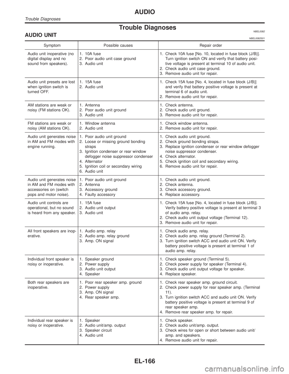
Trouble DiagnosesNBEL0082AUDIO UNITNBEL0082S01
Symptom Possible causes Repair order
Audio unit inoperative (no
digital display and no
sound from speakers).1. 10A fuse
2. Poor audio unit case ground
3. Audio unit1. Check 10A fuse [No. 10, located in fuse block (J/B)].
Turn ignition switch ON and verify that battery posi-
tive voltage is present at terminal 10 of audio unit.
2. Check audio unit case ground.
3. Remove audio unit for repair.
Audio unit presets are lost
when ignition switch is
turned OFF.1. 15A fuse
2. Audio unit1. Check 15A fuse [No. 4, located in fuse block (J/B)]
and verify that battery positive voltage is present at
terminal 6 of audio unit.
2. Remove audio unit for repair.
AM stations are weak or
noisy (FM stations OK).1. Antenna
2. Poor audio unit ground
3. Audio unit1. Check antenna.
2. Check audio unit ground.
3. Remove audio unit for repair.
FM stations are weak or
noisy (AM stations OK).1. Window antenna
2. Audio unit1. Check window antenna.
2. Remove audio unit for repair.
Audio unit generates noise
in AM and FM modes with
engine running.1. Poor audio unit ground
2. Loose or missing ground bonding
straps
3. Ignition condenser or rear window
defogger noise suppressor condenser
4. Alternator
5. Ignition coil or secondary wiring
6. Audio unit1. Check audio unit ground.
2. Check ground bonding straps.
3. Replace ignition condenser or rear window defogger
noise suppressor condenser.
4. Check alternator.
5. Check ignition coil and secondary wiring.
6. Remove audio unit for repair.
Audio unit generates noise
in AM and FM modes with
accessories on (switch
pops and motor noise).1. Poor audio unit ground
2. Antenna
3. Accessory ground
4. Faulty accessory1. Check audio unit ground.
2. Check antenna.
3. Check accessory ground.
4. Replace accessory.
Audio unit controls are
operational, but no sound
is heard from any speaker.1. 15A fuse
2. Audio unit output
3. Audio unit1. Check 15A fuse [No. 4, located in fuse block (J/B)].
Verify battery positive voltage is present at terminal 3
of audio amp. relay.
2. Check audio unit output voltage (Terminal 12).
3. Remove audio unit for repair.
All front speakers are inop-
erative.1. Audio amp. relay
2. Audio amp. relay ground
3. Amp. ON signal1. Check audio amp. relay.
2. Check audio amp. relay ground (Terminal 2).
3. Turn ignition switch ACC and audio unit ON. Verify
battery positive voltage is present at terminal 1 of
audio amp. relay.
Individual front speaker is
noisy or inoperative.1. Speaker ground
2. Power supply
3. Audio unit output
4. Speaker1. Check speaker ground (Terminal 5).
2. Check power supply for speaker (Terminal 4).
3. Check audio unit output voltage for speaker.
4. Replace speaker.
Both rear speakers are
inoperative.1. Poor rear speaker amp. ground
2. Power supply
3. Amp. ON signal
4. Rear speaker amp.1. Check rear speaker amp. ground circuit.
2. Check power supply for rear speaker amp. (Terminal
11).
3. Turn ignition switch ACC and audio unit ON. Verify
battery positive voltage is present at terminal 9 of
rear speaker amp.
4. Remove rear speaker amp. for repair.
Individual rear speaker is
noisy or inoperative.1. Speaker
2. Audio unit/amp. output
3. Speaker circuit
4. Audio unit1. Check speaker.
2. Check audio unit/amp. output.
3. Check wires for open or short between audio unit/
amp. and speakers.
4. Remove audio unit for repair.
AUDIO
Trouble Diagnoses
EL-166
Page 1480 of 2395

System DescriptionNBEL0120DESCRIPTIONNBEL0120S011. Operation FlowNBEL0120S0101
SEL334W
2. Setting The Theft Warning SystemNBEL0120S0102Initial condition
1) Close all doors.
2) Close hood and glass hatch.
Disarmed phase
When the theft warning system is in the disarmed phase, the security indicator lamp blinks every 2.6 seconds.
Pre-armed phase and armed phase
The theft warning system turns into the ªpre-armedº phase when hood, glass hatch and all doors are closed
and the doors are locked by key or multi-remote controller. (The security indicator lamp illuminates.)
After about 30 seconds, the system automatically shifts into the ªarmedº phase (the system is set). (The
security indicator lamp blinks every 2.6 seconds.)
3. Canceling The Set Theft Warning SystemNBEL0120S0103When the following 1) or 2) operation is performed, the armed phase is canceled.
1) Unlock the doors with the key or multi-remote controller.
2) Open the glass hatch with the key.
4. Activating The Alarm Operation of The Theft Warning SystemNBEL0120S0104Make sure the system is in the armed phase. (The security indicator lamp blinks every 2.6 seconds.)
When any of the following operations is performed, the system sounds the horns and flashes the headlamps
for about 50 seconds.
1) Engine hood, glass hatch or any door is opened before unlocking door with key or multi-remote control-
ler.
2) Door is unlocked without using key or multi-remote controller.
3) Disconnecting and connecting the battery connector before canceling armed phase.
POWER SUPPLY AND GROUNDNBEL0120S07Power is supplied at all times
Ithrough 7.5A fuse [No. 24, located in the fuse block (J/B)]
Ito security indicator lamp terminal 1, and
Ito smart entrance control unit terminal 10.
With the ignition switch in the ON or START position, power is supplied
Ithrough 7.5A fuse [No. 11, located in the fuse block (J/B)]
GI
MA
EM
LC
EC
FE
AT
TF
PD
AX
SU
BR
ST
RS
BT
HA
SC
IDX
THEFT WARNING SYSTEM
System Description
EL-295
Page 1514 of 2395
System Description=NBEL0171NATS (Nissan Anti-Theft System) has the following immobilizer functions:
ISince only IVIS (NATS) ignition keys, whose ID nos. have been registered into the ECM and IMMU of IVIS
(NATS), allow the engine to run, operation of a stolen vehicle without an IVIS (NATS) registered key is
prevented by IVIS (NATS).
That is to say, IVIS (NATS) will immobilise the engine if someone tries to start it without the registered key
of IVIS (NATS).
IAll of the originally supplied ignition key IDs (except for card plate key) have been IVIS (NATS) registered.
If requested by the vehicle owner, a maximum of five key IDs can be registered into the IVIS (NATS) com-
ponents.
IThe security indicator blinks when the ignition switch is in ªOFFº or ªACCº position. Therefore, IVIS (NATS)
warns outsiders that the vehicle is equipped with the anti-theft system.
IWhen IVIS (NATS) detects trouble, the security indicator lamp lights up while ignition key is in the ªONº
position.
IIVIS (NATS) trouble diagnoses, system initialization and additional registration of other IVIS (NATS) igni-
tion key IDs must be carried out using CONSULT-II hardware and CONSULT-II IVIS (NATS) software.
When IVIS (NATS) initialization has been completed, the ID of the inserted ignition key is automatically
IVIS (NATS) registered. Then, if necessary, additional registration of other IVIS (NATS) ignition key IDs
can be carried out.
Regarding the procedures of IVIS (NATS) initialization and IVIS (NATS) ignition key ID registration, refer
to CONSULT-II operation manual, IVIS/NVIS.
IWhen servicing a malfunction of the IVIS (NATS) (indicated by lighting up of Security Indicator
Lamp) or registering another IVIS (NATS) ignition key ID no., it is necessary to re-register original
key identification. Therefore, be sure to receive ALL KEYS from vehicle owner.
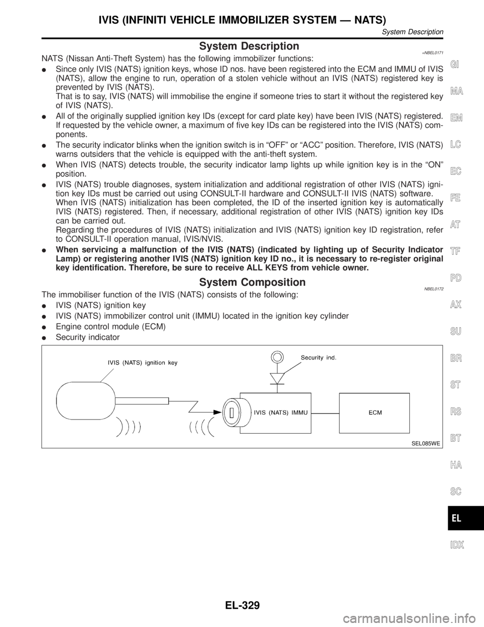
System CompositionNBEL0172The immobiliser function of the IVIS (NATS) consists of the following:
IIVIS (NATS) ignition key
IIVIS (NATS) immobilizer control unit (IMMU) located in the ignition key cylinder
IEngine control module (ECM)
ISecurity indicator
SEL085WE
GI
MA
EM
LC
EC
FE
AT
TF
PD
AX
SU
BR
ST
RS
BT
HA
SC
IDX
IVIS (INFINITI VEHICLE IMMOBILIZER SYSTEM Ð NATS)
System Description
EL-329
Page 1582 of 2395
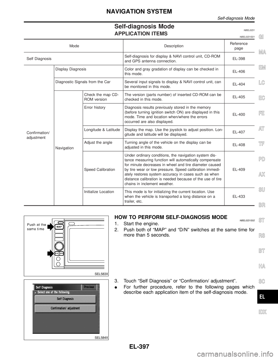
Self-diagnosis ModeNBEL0231APPLICATION ITEMSNBEL0231S01
Mode DescriptionReference
page
Self DiagnosisSelf-diagnosis for display & NAVI control unit, CD-ROM
and GPS antenna connection.EL-398
Confirmation/
adjustmentDisplay Diagnosis Color and gray gradation of display can be checked in
this mode.EL-406
Diagnostic Signals from the Car Several input signals to display & NAVI control unit, can
be monitored in this mode.EL-404
NavigationCheck the map CD-
ROM versionThe version (parts number) of inserted CD-ROM can be
checked in this mode.EL-405
Error history Diagnosis results previously stored in the memory
(before turning ignition switch ON) are displayed in this
mode. Time and location when/where the errors
occurred are also displayed.EL-400
Longitude & Latitude Display the map. Use the joystick to adjust position. Lon-
gitude and latitude will be displayed.EL-407
Adjust the angle Turning angle of the vehicle on the display can be
adjusted in this mode.EL-408
Speed CalibrationUnder ordinary conditions, the navigation system dis-
tance measuring function will automatically compensate
for minute decreases in wheel and tire diameter caused
by tire wear or low pressure. Speed calibration immedi-
ately restores system accuracy in cases such as when
distance calibration is needed because of the use of tire
chains in inclement weather.EL-409
Initialize Location This mode is for initializing the current location. Use
when the vehicle is transported a long distance on a
trailer, etc.EL-433
SEL583X
HOW TO PERFORM SELF-DIAGNOSIS MODENBEL0231S021. Start the engine.
2. Push both of ªMAPº and ªD/Nº switches at the same time for
more than 5 seconds.
SEL584X
3. Touch ªSelf Diagnosisº or ªConfirmation/ adjustmentº.
IFor further procedure, refer to the following pages which
describe each application item of the self-diagnosis mode.
GI
MA
EM
LC
EC
FE
AT
TF
PD
AX
SU
BR
ST
RS
BT
HA
SC
IDX
NAVIGATION SYSTEM
Self-diagnosis Mode
EL-397
Page 1585 of 2395
Confirmation/Adjustment Mode=NBEL0232ªERROR HISTORYº MODENBEL0232S01DescriptionNBEL0232S0101In this mode, historical errors of the system are displayed with the
following data.
IHow many times the error was detected
IThe last time data when the error was detected
IThe last place where the error was detected
NOTE:
IThe number of errors can be counted up to 50 times. More
than 51 times will be indicated as 50 times.
IMalfunction of the GPS board (inside the display & NAVI
control unit) will result in the display of incorrect time
data.
IWhen an error occurs, an incorrect position marker
appears on the display. The accuracy of the display data
(position marker) will be affected.
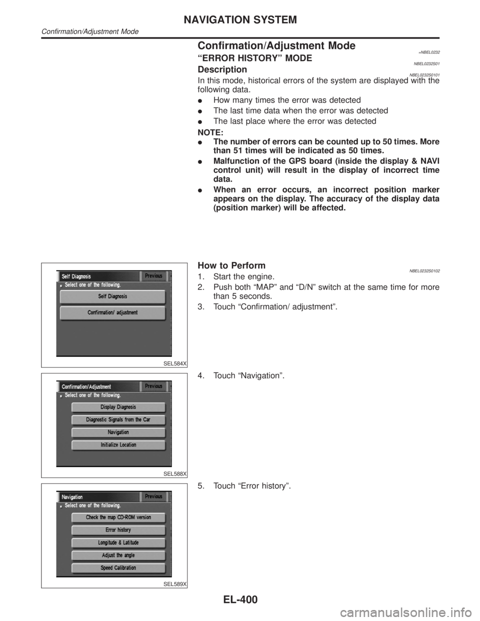
SEL584X
How to PerformNBEL0232S01021. Start the engine.
2. Push both ªMAPº and ªD/Nº switch at the same time for more
than 5 seconds.
3. Touch ªConfirmation/ adjustmentº.
SEL588X
4. Touch ªNavigationº.
SEL589X
5. Touch ªError historyº.
NAVIGATION SYSTEM
Confirmation/Adjustment Mode
EL-400
Page 1586 of 2395
SEL590X
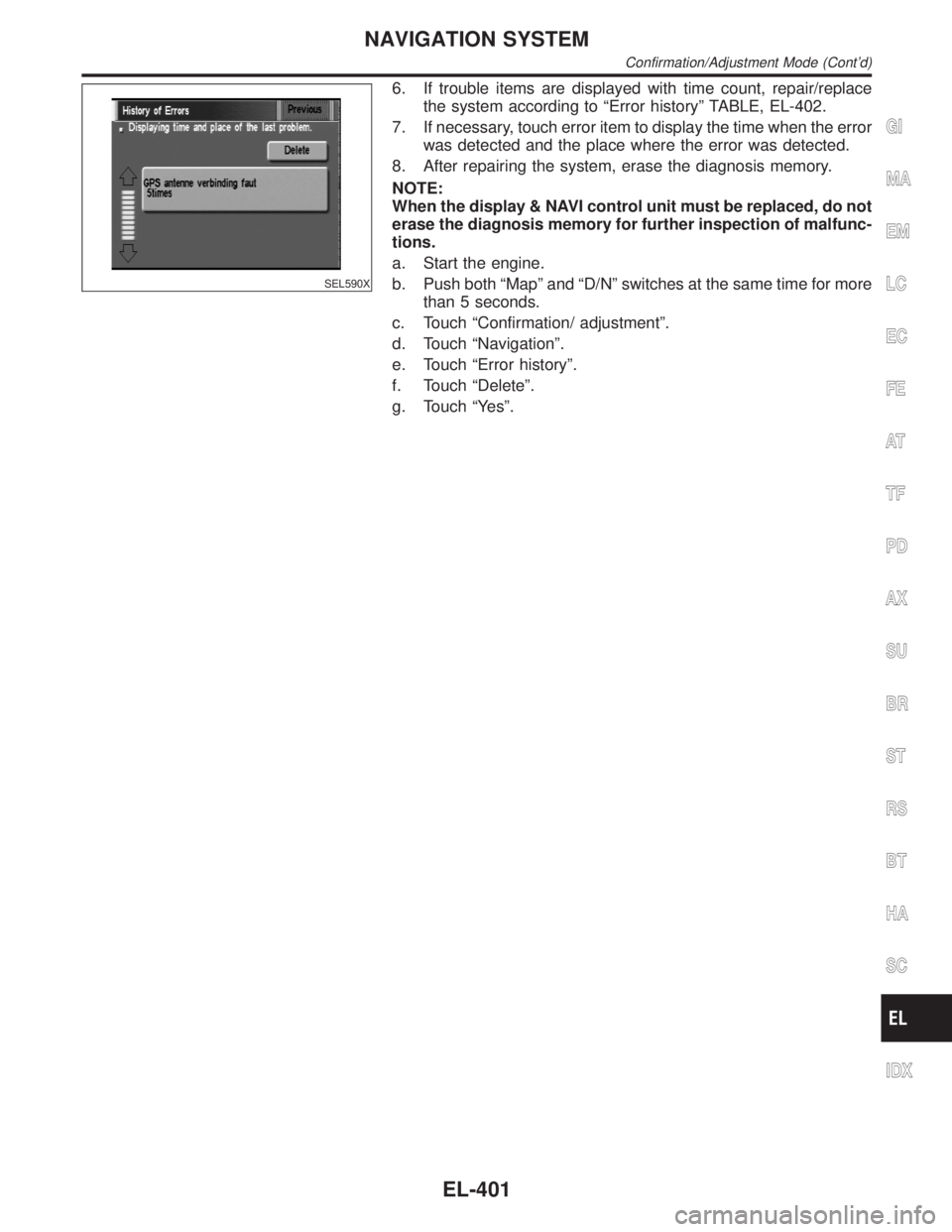
6. If trouble items are displayed with time count, repair/replace
the system according to ªError historyº TABLE, EL-402.
7. If necessary, touch error item to display the time when the error
was detected and the place where the error was detected.
8. After repairing the system, erase the diagnosis memory.
NOTE:
When the display & NAVI control unit must be replaced, do not
erase the diagnosis memory for further inspection of malfunc-
tions.
a. Start the engine.
b. Push both ªMapº and ªD/Nº switches at the same time for more
than 5 seconds.
c. Touch ªConfirmation/ adjustmentº.
d. Touch ªNavigationº.
e. Touch ªError historyº.
f. Touch ªDeleteº.
g. Touch ªYesº.
GI
MA
EM
LC
EC
FE
AT
TF
PD
AX
SU
BR
ST
RS
BT
HA
SC
IDX
NAVIGATION SYSTEM
Confirmation/Adjustment Mode (Cont'd)
EL-401
Page 1589 of 2395
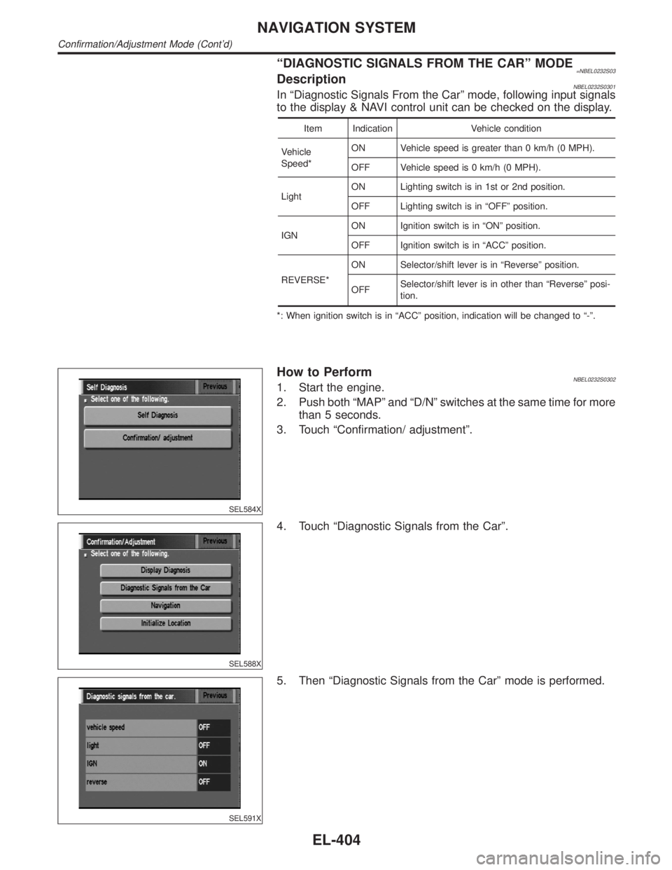
ªDIAGNOSTIC SIGNALS FROM THE CARº MODE=NBEL0232S03DescriptionNBEL0232S0301In ªDiagnostic Signals From the Carº mode, following input signals
to the display & NAVI control unit can be checked on the display.
Item Indication Vehicle condition
Vehicle
Speed*ON Vehicle speed is greater than 0 km/h (0 MPH).
OFF Vehicle speed is 0 km/h (0 MPH).
LightON Lighting switch is in 1st or 2nd position.
OFF Lighting switch is in ªOFFº position.
IGNON Ignition switch is in ªONº position.
OFF Ignition switch is in ªACCº position.
REVERSE*ON Selector/shift lever is in ªReverseº position.
OFFSelector/shift lever is in other than ªReverseº posi-
tion.
*: When ignition switch is in ªACCº position, indication will be changed to ª-º.
SEL584X
How to PerformNBEL0232S03021. Start the engine.
2. Push both ªMAPº and ªD/Nº switches at the same time for more
than 5 seconds.
3. Touch ªConfirmation/ adjustmentº.
SEL588X
4. Touch ªDiagnostic Signals from the Carº.
SEL591X
5. Then ªDiagnostic Signals from the Carº mode is performed.
NAVIGATION SYSTEM
Confirmation/Adjustment Mode (Cont'd)
EL-404