Page 1590 of 2395
SEL584X
ªCHECK THE MAP CD-ROM VERSIONº MODE=NBEL0232S04How to PerformNBEL0232S04011. Start the engine.
2. Push both ªMAPº and ªD/Nº switches at the same time for more
than 5 seconds.
3. Touch ªConfirmation/ adjustmentº.
SEL588X
4. Touch ªNavigationº.
SEL589X
5. Touch ªCheck the map CD-ROM versionº.
SEL592X
6. The version (parts number) of CD-ROM loaded to the display
and NAVI control unit will be displayed.
GI
MA
EM
LC
EC
FE
AT
TF
PD
AX
SU
BR
ST
RS
BT
HA
SC
IDX
NAVIGATION SYSTEM
Confirmation/Adjustment Mode (Cont'd)
EL-405
Page 1591 of 2395
ªDISPLAY DIAGNOSISº MODE=NBEL0232S05DescriptionNBEL0232S0501Use the ªDiagnosis Displayº mode to check the display color bright-
ness and shading. The display & NAVI control unit must be
replaced if the color brightness and shading are abnormal.
SEL584X
How to PerformNBEL0232S05021. Start the engine.
2. Push both ªMAPº and ªD/Nº switches at the same time for more
than 5 seconds.
3. Touch ªConfirmation/ adjustmentº.
SEL588X
4. Touch ªDisplay Diagnosisº.
SEL593X
5. Touch ªDisplay color spectrum barº or ªDisplay gradation barº.
6. Then color bar/gray scale will be displayed.
SEL594X
NAVIGATION SYSTEM
Confirmation/Adjustment Mode (Cont'd)
EL-406
Page 1595 of 2395

Setting Mode=NBEL0233APPLICATION ITEMSNBEL0233S01
Mode Description Reference page
GPS Information The GPS includes longtitude, latitude and altitude (distance above sea level) of the
present vehicle position, and current date and time for the area in which the vehicle is
being driven.
Also indicated are the GPS reception conditions and the GPS satellite position.EL-410
Quick Stop Customer
SettingOne facility of your selection can be added to your Quick Stop.
EL-413
Route Priorities Priorities of search request and automatic re-searching can be set for route search. EL-414
Tracking Tracking to the present vehicle position can be displayed. EL-414
Display Setting The following display settings can be customized.
IDisplay color (Day mode or Night mode)
IBrightness of displayEL-412
Heading Heading of the map display can be customized for either north heading or the actual
driving direction of the vehicle.EL-415
Nearby Display Icons Icons of facilities can be displayed.
Facilities to be displayed can be selected from the variety of selections.EL-416
Adjust Current Loca-
tionCurrent location of position marker can be adjusted. Direction of position marker also
can be calibrated when heading direction of the vehicle on the display is not matched
with the actual direction.EL-411
Avoid Area Setting Particular area can be avoided when routing. Ð
Beep On/Off Beep sounds which correspond to the system operation can be activated/deactivated. EL-412
Clear Memory Address book, Previous destination or Avoid area can be deleted. EL-416
SEL597X
HOW TO PERFORM CONTROL PANEL MODENBEL0233S021. Start the engine.
2. Push ªMAPº switch.
IFor further procedures, refer to the following pages which
describe each application item of the control panel mode.
SEL598X
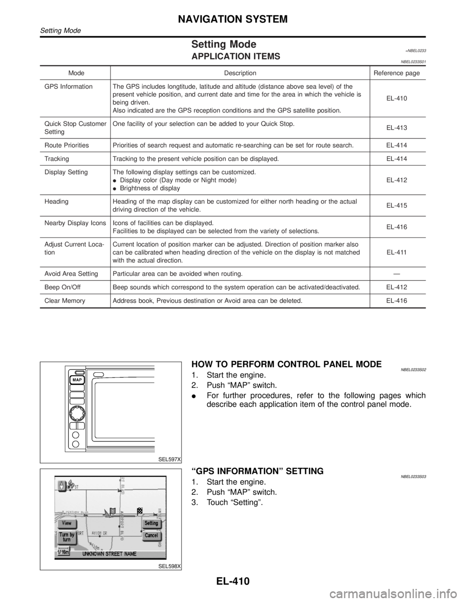
ªGPS INFORMATIONº SETTINGNBEL0233S031. Start the engine.
2. Push ªMAPº switch.
3. Touch ªSettingº.
NAVIGATION SYSTEM
Setting Mode
EL-410
Page 1625 of 2395
How to Read Harness LayoutNBEL0131
SEL252V
The following Harness Layouts use a map style grid to help locate connectors on the drawings:
IMain Harness
IEngine Room Harness (Engine Compartment)
IEngine Control Harness
TO USE THE GRID REFERENCENBEL0131S011. Find the desired connector number on the connector list.
2. Find the grid reference.
3. On the drawing, find the crossing of the grid reference letter column and number row.
4. Find the connector number in the crossing zone.
5. Follow the line (if used) to the connector.
CONNECTOR SYMBOLNBEL0131S02Main symbols of connector (in Harness Layout) are indicated in the below.
Connector typeWater proof type Standard type
Male Female Male Female
ICavity: Less than 4
IRelay connector
ICavity: From 5 to 8
ICavity: More than 9
ÐÐ
IGround terminal etc.
Ð
HARNESS LAYOUT
How to Read Harness Layout
EL-440
Page 1631 of 2395
Engine Control HarnessNBEL0135
MEL077M
HARNESS LAYOUT
Engine Control Harness
EL-446
Page 1632 of 2395
MEL078M
GI
MA
EM
LC
EC
FE
AT
TF
PD
AX
SU
BR
ST
RS
BT
HA
SC
IDX
HARNESS LAYOUT
Engine Control Harness (Cont'd)
EL-447
Page 1642 of 2395

NBEL0145
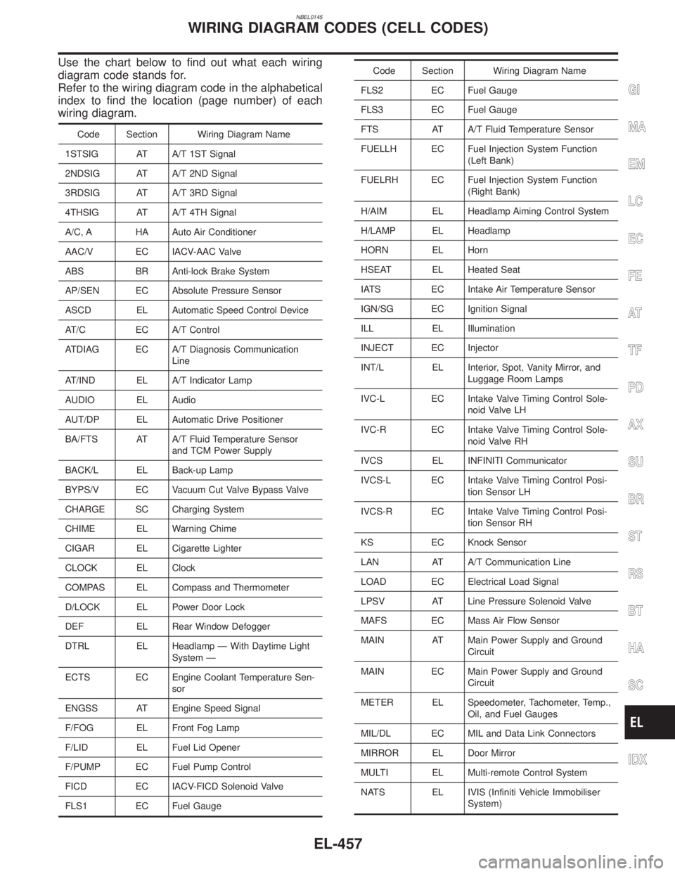
Use the chart below to find out what each wiring
diagram code stands for.
Refer to the wiring diagram code in the alphabetical
index to find the location (page number) of each
wiring diagram.
Code Section Wiring Diagram Name
1STSIG AT A/T 1ST Signal
2NDSIG AT A/T 2ND Signal
3RDSIG AT A/T 3RD Signal
4THSIG AT A/T 4TH Signal
A/C, A HA Auto Air Conditioner
AAC/V EC IACV-AAC Valve
ABS BR Anti-lock Brake System
AP/SEN EC Absolute Pressure Sensor
ASCD EL Automatic Speed Control Device
AT/C EC A/T Control
ATDIAG EC A/T Diagnosis Communication
Line
AT/IND EL A/T Indicator Lamp
AUDIO EL Audio
AUT/DP EL Automatic Drive Positioner
BA/FTS AT A/T Fluid Temperature Sensor
and TCM Power Supply
BACK/L EL Back-up Lamp
BYPS/V EC Vacuum Cut Valve Bypass Valve
CHARGE SC Charging System
CHIME EL Warning Chime
CIGAR EL Cigarette Lighter
CLOCK EL Clock
COMPAS EL Compass and Thermometer
D/LOCK EL Power Door Lock
DEF EL Rear Window Defogger
DTRL EL Headlamp Ð With Daytime Light
System Ð
ECTS EC Engine Coolant Temperature Sen-
sor
ENGSS AT Engine Speed Signal
F/FOG EL Front Fog Lamp
F/LID EL Fuel Lid Opener
F/PUMP EC Fuel Pump Control
FICD EC IACV-FICD Solenoid Valve
FLS1 EC Fuel Gauge
Code Section Wiring Diagram Name
FLS2 EC Fuel Gauge
FLS3 EC Fuel Gauge
FTS AT A/T Fluid Temperature Sensor
FUELLH EC Fuel Injection System Function
(Left Bank)
FUELRH EC Fuel Injection System Function
(Right Bank)
H/AIM EL Headlamp Aiming Control System
H/LAMP EL Headlamp
HORN EL Horn
HSEAT EL Heated Seat
IATS EC Intake Air Temperature Sensor
IGN/SG EC Ignition Signal
ILL EL Illumination
INJECT EC Injector
INT/L EL Interior, Spot, Vanity Mirror, and
Luggage Room Lamps
IVC-L EC Intake Valve Timing Control Sole-
noid Valve LH
IVC-R EC Intake Valve Timing Control Sole-
noid Valve RH
IVCS EL INFINITI Communicator
IVCS-L EC Intake Valve Timing Control Posi-
tion Sensor LH
IVCS-R EC Intake Valve Timing Control Posi-
tion Sensor RH
KS EC Knock Sensor
LAN AT A/T Communication Line
LOAD EC Electrical Load Signal
LPSV AT Line Pressure Solenoid Valve
MAFS EC Mass Air Flow Sensor
MAIN AT Main Power Supply and Ground
Circuit
MAIN EC Main Power Supply and Ground
Circuit
METER EL Speedometer, Tachometer, Temp.,
Oil, and Fuel Gauges
MIL/DL EC MIL and Data Link Connectors
MIRROR EL Door Mirror
MULTI EL Multi-remote Control System
NATS EL IVIS (Infiniti Vehicle Immobiliser
System)
GI
MA
EM
LC
EC
FE
AT
TF
PD
AX
SU
BR
ST
RS
BT
HA
SC
IDX
WIRING DIAGRAM CODES (CELL CODES)
EL-457
Page 1654 of 2395
SEM484GA
1. Heated oxygen sensor 1 (front)
(bank 1)
2. Heated oxygen sensor 1 (front)
(bank 2)
3. TWC (manifold)4. Thermostat with water inlet
5. Exhaust manifold
6. Thermal transmitter
7. Engine coolant temperature8. Water control valve
9. Water outlet housing
10. Cylinder block water outlet
GI
MA
LC
EC
FE
AT
TF
PD
AX
SU
BR
ST
RS
BT
HA
SC
EL
IDX
OUTER COMPONENT PARTS
Removal and Installation (Cont'd)
EM-11