2001 INFINITI QX4 lock
[x] Cancel search: lockPage 1351 of 2395
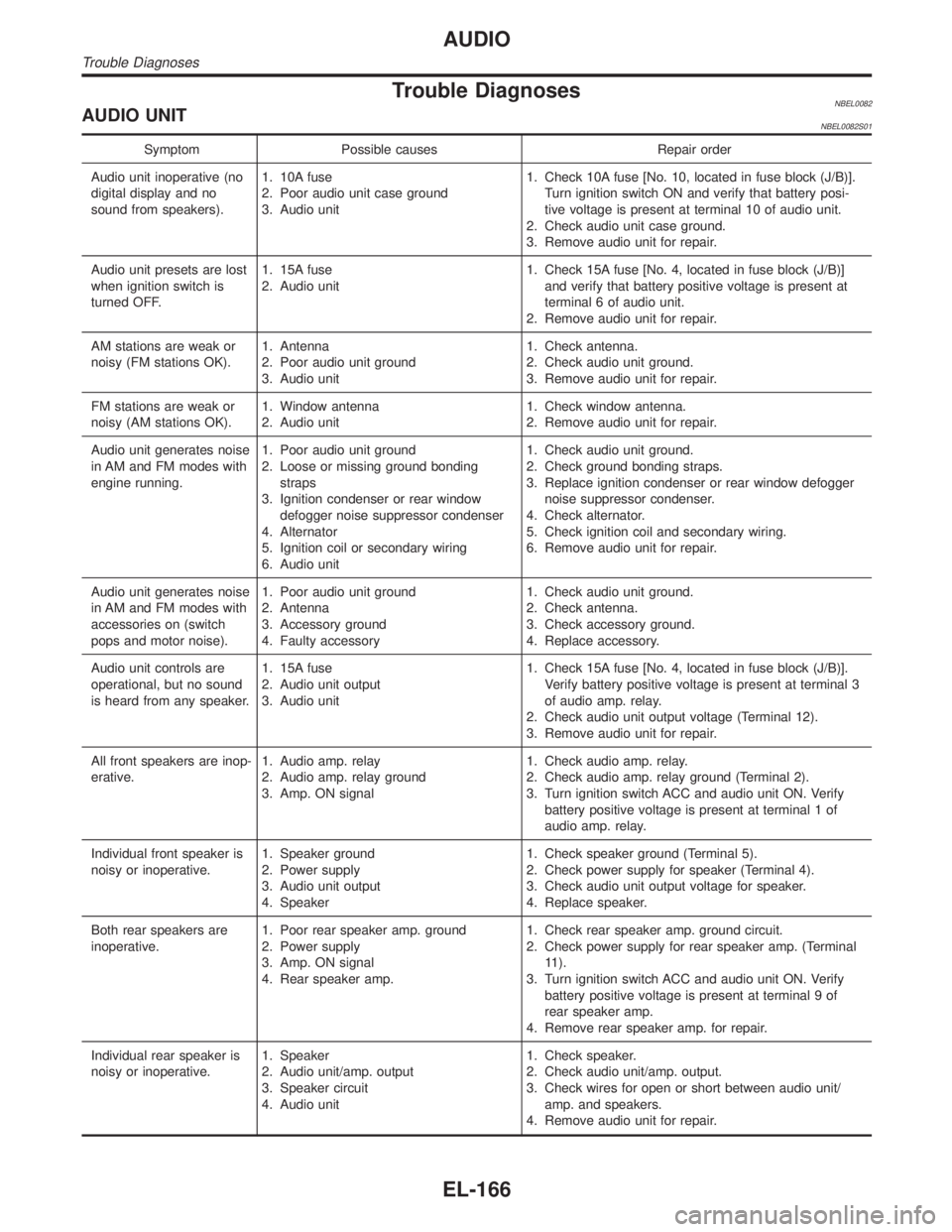
Trouble DiagnosesNBEL0082AUDIO UNITNBEL0082S01
Symptom Possible causes Repair order
Audio unit inoperative (no
digital display and no
sound from speakers).1. 10A fuse
2. Poor audio unit case ground
3. Audio unit1. Check 10A fuse [No. 10, located in fuse block (J/B)].
Turn ignition switch ON and verify that battery posi-
tive voltage is present at terminal 10 of audio unit.
2. Check audio unit case ground.
3. Remove audio unit for repair.
Audio unit presets are lost
when ignition switch is
turned OFF.1. 15A fuse
2. Audio unit1. Check 15A fuse [No. 4, located in fuse block (J/B)]
and verify that battery positive voltage is present at
terminal 6 of audio unit.
2. Remove audio unit for repair.
AM stations are weak or
noisy (FM stations OK).1. Antenna
2. Poor audio unit ground
3. Audio unit1. Check antenna.
2. Check audio unit ground.
3. Remove audio unit for repair.
FM stations are weak or
noisy (AM stations OK).1. Window antenna
2. Audio unit1. Check window antenna.
2. Remove audio unit for repair.
Audio unit generates noise
in AM and FM modes with
engine running.1. Poor audio unit ground
2. Loose or missing ground bonding
straps
3. Ignition condenser or rear window
defogger noise suppressor condenser
4. Alternator
5. Ignition coil or secondary wiring
6. Audio unit1. Check audio unit ground.
2. Check ground bonding straps.
3. Replace ignition condenser or rear window defogger
noise suppressor condenser.
4. Check alternator.
5. Check ignition coil and secondary wiring.
6. Remove audio unit for repair.
Audio unit generates noise
in AM and FM modes with
accessories on (switch
pops and motor noise).1. Poor audio unit ground
2. Antenna
3. Accessory ground
4. Faulty accessory1. Check audio unit ground.
2. Check antenna.
3. Check accessory ground.
4. Replace accessory.
Audio unit controls are
operational, but no sound
is heard from any speaker.1. 15A fuse
2. Audio unit output
3. Audio unit1. Check 15A fuse [No. 4, located in fuse block (J/B)].
Verify battery positive voltage is present at terminal 3
of audio amp. relay.
2. Check audio unit output voltage (Terminal 12).
3. Remove audio unit for repair.
All front speakers are inop-
erative.1. Audio amp. relay
2. Audio amp. relay ground
3. Amp. ON signal1. Check audio amp. relay.
2. Check audio amp. relay ground (Terminal 2).
3. Turn ignition switch ACC and audio unit ON. Verify
battery positive voltage is present at terminal 1 of
audio amp. relay.
Individual front speaker is
noisy or inoperative.1. Speaker ground
2. Power supply
3. Audio unit output
4. Speaker1. Check speaker ground (Terminal 5).
2. Check power supply for speaker (Terminal 4).
3. Check audio unit output voltage for speaker.
4. Replace speaker.
Both rear speakers are
inoperative.1. Poor rear speaker amp. ground
2. Power supply
3. Amp. ON signal
4. Rear speaker amp.1. Check rear speaker amp. ground circuit.
2. Check power supply for rear speaker amp. (Terminal
11).
3. Turn ignition switch ACC and audio unit ON. Verify
battery positive voltage is present at terminal 9 of
rear speaker amp.
4. Remove rear speaker amp. for repair.
Individual rear speaker is
noisy or inoperative.1. Speaker
2. Audio unit/amp. output
3. Speaker circuit
4. Audio unit1. Check speaker.
2. Check audio unit/amp. output.
3. Check wires for open or short between audio unit/
amp. and speakers.
4. Remove audio unit for repair.
AUDIO
Trouble Diagnoses
EL-166
Page 1354 of 2395
![INFINITI QX4 2001 Factory Service Manual System DescriptionNBEL0084Power is supplied at all times
Ithrough 7.5A fuse [No. 24, located in the fuse block (J/B)]
Ito power antenna terminal 6.
Ground is supplied to the power antenna terminal 2 t INFINITI QX4 2001 Factory Service Manual System DescriptionNBEL0084Power is supplied at all times
Ithrough 7.5A fuse [No. 24, located in the fuse block (J/B)]
Ito power antenna terminal 6.
Ground is supplied to the power antenna terminal 2 t](/manual-img/42/57027/w960_57027-1353.png)
System DescriptionNBEL0084Power is supplied at all times
Ithrough 7.5A fuse [No. 24, located in the fuse block (J/B)]
Ito power antenna terminal 6.
Ground is supplied to the power antenna terminal 2 through body grounds M4, M66 and M147.
When the audio unit is turned to the ON position, battery positive voltage is supplied
Ithrough audio unit terminal 5
Ito power antenna terminal 4.
The antenna raises and is held in the extended position.
When the audio unit is turned to the OFF position, battery positive voltage is interrupted
Ifrom audio unit terminal 5
Ito power antenna terminal 4.
The antenna retracts.GI
MA
EM
LC
EC
FE
AT
TF
PD
AX
SU
BR
ST
RS
BT
HA
SC
IDX
AUDIO ANTENNA
System Description
EL-169
Page 1356 of 2395
Trouble DiagnosesNBEL0086POWER ANTENNANBEL0086S01
Symptom Possible causes Repair order
Power antenna does not
operate.1. 7.5A fuse
2. Audio unit signal
3. Grounds M4, M66 and M1471. Check 7.5A fuse [No. 24, located in fuse block (J/B)].
Verify that battery positive voltage is present at termi-
nal 6 of power antenna.
2. Turn ignition switch and audio unit ON. Verify that
battery positive voltage is present at terminal 4 of
power antenna.
3. Check grounds M4, M66 and M147.
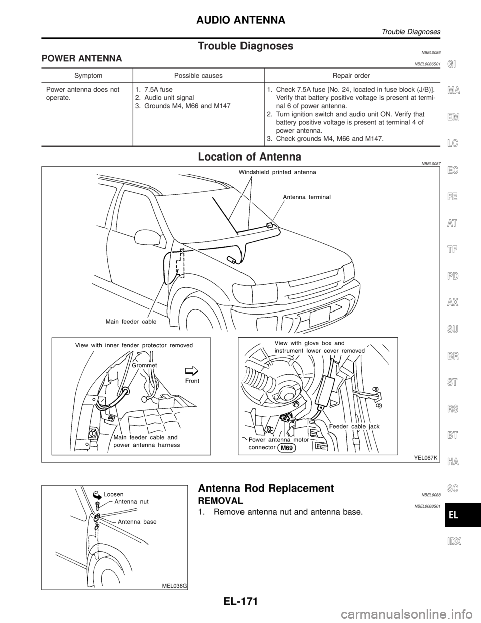
Location of AntennaNBEL0087
YEL067K
MEL036G
Antenna Rod ReplacementNBEL0088REMOVALNBEL0088S011. Remove antenna nut and antenna base.
GI
MA
EM
LC
EC
FE
AT
TF
PD
AX
SU
BR
ST
RS
BT
HA
SC
IDX
AUDIO ANTENNA
Trouble Diagnoses
EL-171
Page 1361 of 2395
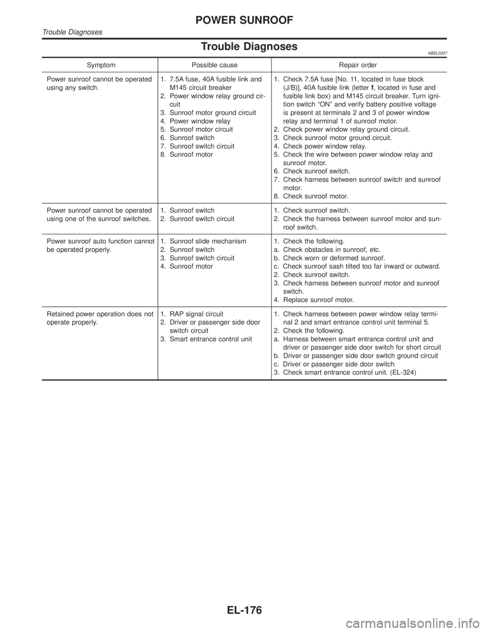
Trouble DiagnosesNBEL0207
Symptom Possible cause Repair order
Power sunroof cannot be operated
using any switch.1. 7.5A fuse, 40A fusible link and
M145 circuit breaker
2. Power window relay ground cir-
cuit
3. Sunroof motor ground circuit
4. Power window relay
5. Sunroof motor circuit
6. Sunroof switch
7. Sunroof switch circuit
8. Sunroof motor1. Check 7.5A fuse [No. 11, located in fuse block
(J/B)], 40A fusible link (letterf, located in fuse and
fusible link box) and M145 circuit breaker. Turn igni-
tion switch ªONº and verify battery positive voltage
is present at terminals 2 and 3 of power window
relay and terminal 1 of sunroof motor.
2. Check power window relay ground circuit.
3. Check sunroof motor ground circuit.
4. Check power window relay.
5. Check the wire between power window relay and
sunroof motor.
6. Check sunroof switch.
7. Check harness between sunroof switch and sunroof
motor.
8. Check sunroof motor.
Power sunroof cannot be operated
using one of the sunroof switches.1. Sunroof switch
2. Sunroof switch circuit1. Check sunroof switch.
2. Check the harness between sunroof motor and sun-
roof switch.
Power sunroof auto function cannot
be operated properly.1. Sunroof slide mechanism
2. Sunroof switch
3. Sunroof switch circuit
4. Sunroof motor1. Check the following.
a. Check obstacles in sunroof, etc.
b. Check worn or deformed sunroof.
c. Check sunroof sash tilted too far inward or outward.
2. Check sunroof switch.
3. Check harness between sunroof motor and sunroof
switch.
4. Replace sunroof motor.
Retained power operation does not
operate properly.1. RAP signal circuit
2. Driver or passenger side door
switch circuit
3. Smart entrance control unit1. Check harness between power window relay termi-
nal 2 and smart entrance control unit terminal 5.
2. Check the following.
a. Harness between smart entrance control unit and
driver or passenger side door switch for short circuit
b. Driver or passenger side door switch ground circuit
c. Driver or passenger side door switch
3. Check smart entrance control unit. (EL-324)
POWER SUNROOF
Trouble Diagnoses
EL-176
Page 1363 of 2395
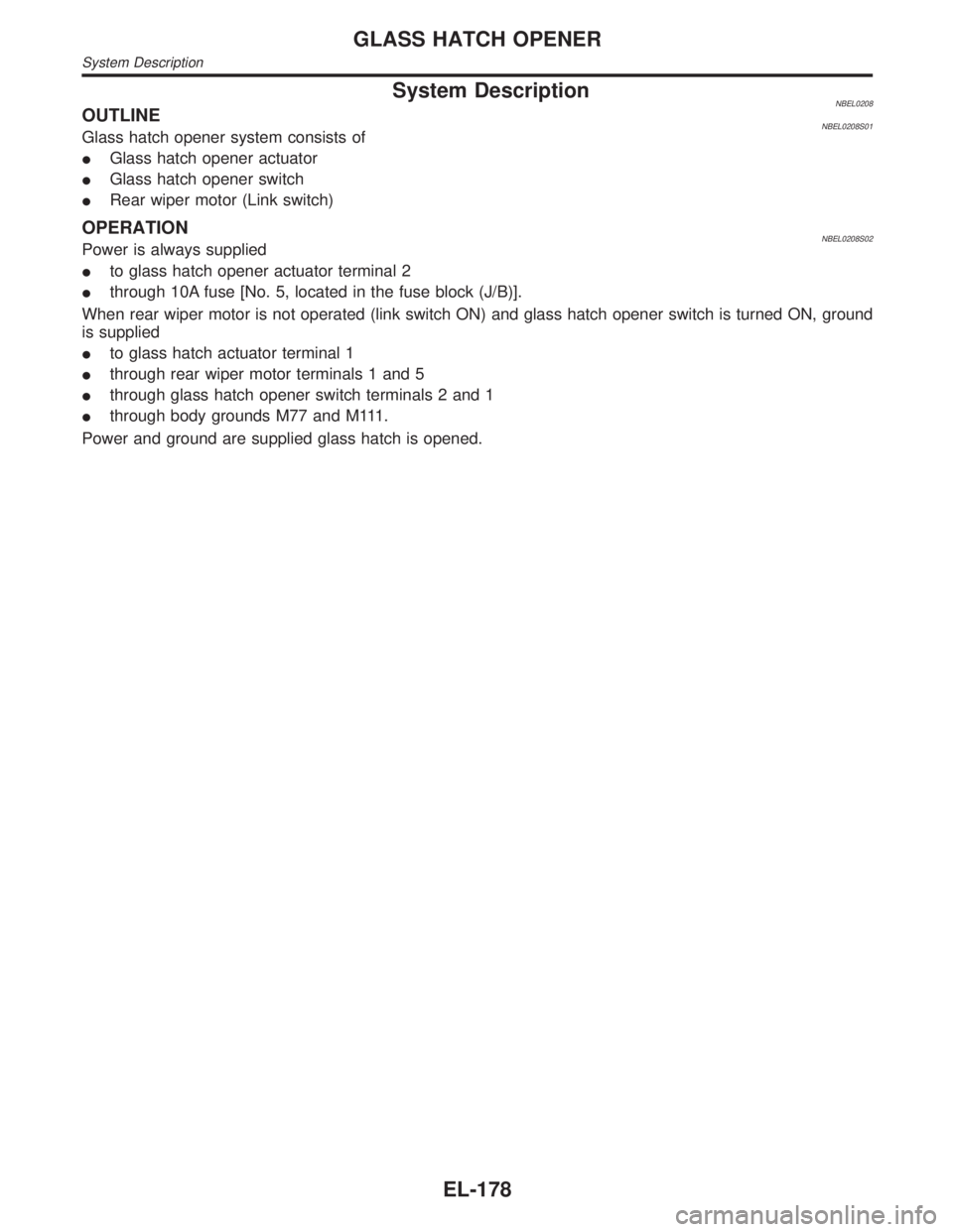
System DescriptionNBEL0208OUTLINENBEL0208S01Glass hatch opener system consists of
IGlass hatch opener actuator
IGlass hatch opener switch
IRear wiper motor (Link switch)
OPERATIONNBEL0208S02Power is always supplied
Ito glass hatch opener actuator terminal 2
Ithrough 10A fuse [No. 5, located in the fuse block (J/B)].
When rear wiper motor is not operated (link switch ON) and glass hatch opener switch is turned ON, ground
is supplied
Ito glass hatch actuator terminal 1
Ithrough rear wiper motor terminals 1 and 5
Ithrough glass hatch opener switch terminals 2 and 1
Ithrough body grounds M77 and M111.
Power and ground are supplied glass hatch is opened.
GLASS HATCH OPENER
System Description
EL-178
Page 1402 of 2395
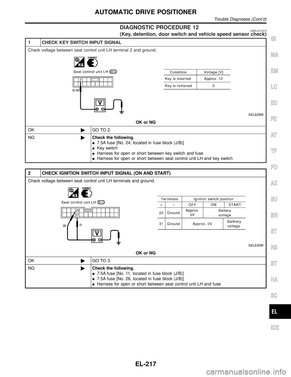
DIAGNOSTIC PROCEDURE 12=NBEL0214S15(Key, detention, door switch and vehicle speed sensor check)
1 CHECK KEY SWITCH INPUT SIGNAL
Check voltage between seat control unit LH terminal 2 and ground.
SEL629W
OK or NG
OK©GO TO 2.
NG©Check the following.
I7.5A fuse [No. 24, located in fuse block (J/B)]
IKey switch
IHarness for open or short between key switch and fuse
IHarness for open or short between seat control unit LH and key switch
2 CHECK IGNITION SWITCH INPUT SIGNAL (ON AND START)
Check voltage between seat control unit LH terminals and ground.
SEL630W
OK or NG
OK©GO TO 3.
NG©Check the following.
I7.5A fuse [No. 11, located in fuse block (J/B)]
I7.5A fuse [No. 26, located in fuse block (J/B)]
IHarness for open or short between seat control unit LH and fuse
GI
MA
EM
LC
EC
FE
AT
TF
PD
AX
SU
BR
ST
RS
BT
HA
SC
IDX
AUTOMATIC DRIVE POSITIONER
Trouble Diagnoses (Cont'd)
EL-217
Page 1405 of 2395
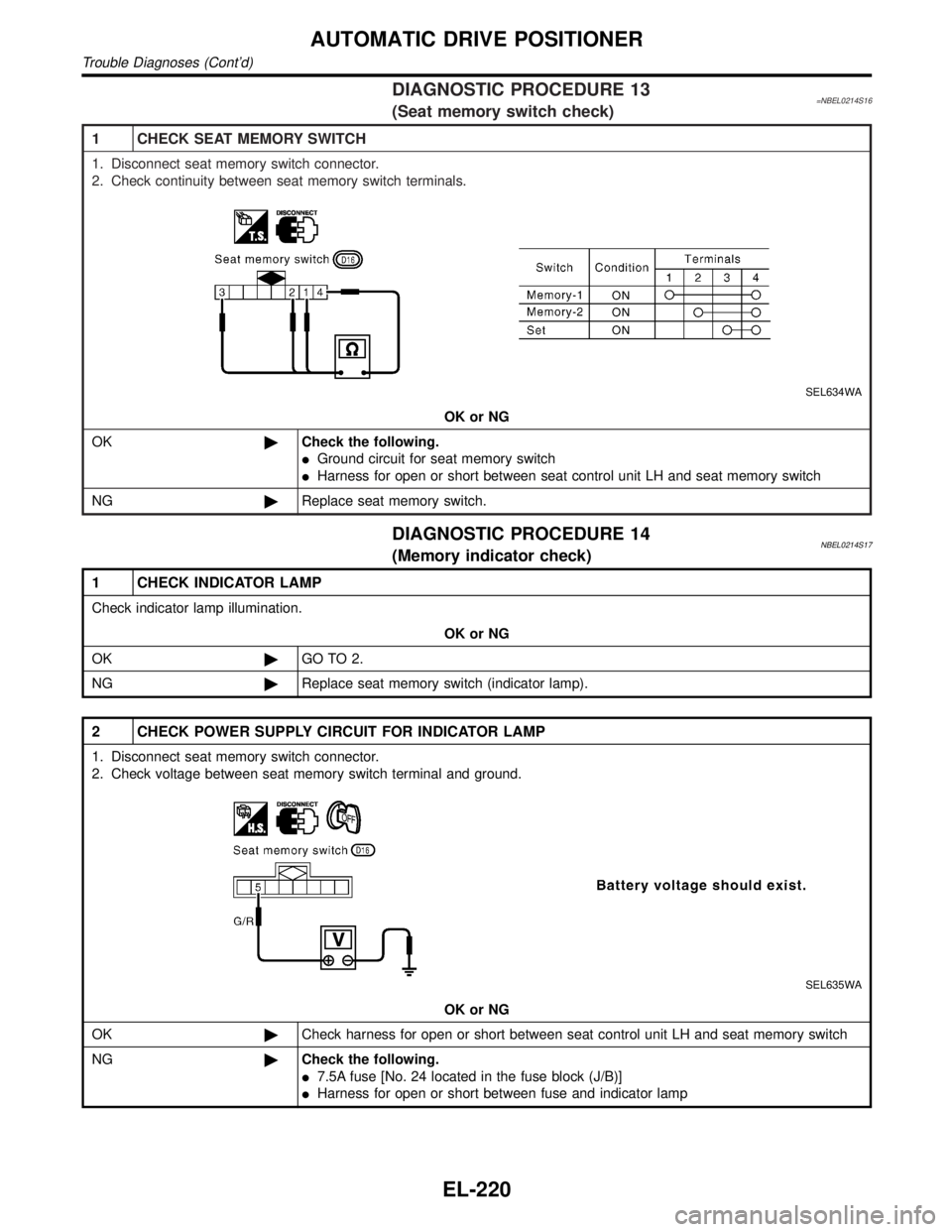
DIAGNOSTIC PROCEDURE 13=NBEL0214S16(Seat memory switch check)
1 CHECK SEAT MEMORY SWITCH
1. Disconnect seat memory switch connector.
2. Check continuity between seat memory switch terminals.
SEL634WA
OK or NG
OK©Check the following.
IGround circuit for seat memory switch
IHarness for open or short between seat control unit LH and seat memory switch
NG©Replace seat memory switch.
DIAGNOSTIC PROCEDURE 14NBEL0214S17(Memory indicator check)
1 CHECK INDICATOR LAMP
Check indicator lamp illumination.
OK or NG
OK©GO TO 2.
NG©Replace seat memory switch (indicator lamp).
2 CHECK POWER SUPPLY CIRCUIT FOR INDICATOR LAMP
1. Disconnect seat memory switch connector.
2. Check voltage between seat memory switch terminal and ground.
SEL635WA
OK or NG
OK©Check harness for open or short between seat control unit LH and seat memory switch
NG©Check the following.
I7.5A fuse [No. 24 located in the fuse block (J/B)]
IHarness for open or short between fuse and indicator lamp
AUTOMATIC DRIVE POSITIONER
Trouble Diagnoses (Cont'd)
EL-220
Page 1407 of 2395
System DescriptionNBEL0216Refer to Owner's Manual for ASCD operating instructions.
POWER SUPPLY AND GROUNDNBEL0216S01Power is supplied at all times:
Ithrough 10A fuse [No. 14, located in the fuse block (J/B)]
Ito the stop lamp switch terminal 1, and
Ithrough 7.5A fuse (No. 52, located in fuse and fusible link box)
Ito the horn relay terminals 1 and 3.
When ignition switch is in the ON or START position, power is supplied:
Ithrough 7.5A fuse [No. 11, located in the fuse block (J/B)]
Ito ASCD brake switch terminal 1 and
Ito ASCD control unit terminal 5,
Ithrough 10A fuse [No. 18, located in the fuse block (J/B)]
Ito park/neutral position relay terminal 1,
Ithrough 10A fuse [No. 8, located in the fuse block (J/B)]
Ito combination meter terminal 66, and
When park/neutral position switch is in the P or N position, ground is supplied:
Ito park/neutral position relay terminal 2
Ithrough park/neutral position switch and body grounds B55 and B75.
When ASCD main switch is depressed (ON), ground is supplied:
Ito ASCD control unit terminal 9
Ifrom ASCD steering switch terminal 4
Ito ASCD steering switch terminal 5
Ithrough body grounds M4, M66 and M147
then ASCD control unit holds CRUISE condition and illuminates CRUISE indicator.
Ground is supplied:
Ifrom ASCD control unit terminal 15
Ito combination meter terminal 46.
OPERATIONNBEL0216S02Set OperationNBEL0216S0201To activate the ASCD, all following conditions must exist.
IGround supply to ASCD control unit terminal 9 (Main switch is in ON position.)
IPower supply to ASCD control unit terminal 8 (Brake pedal is released and A/T selector lever is in other
than P and N position.)
IVehicle speed is between 40 km/h (25 MPH) and 144 km/h (89 MPH). (Signal from combination meter)
When the SET/COAST switch is depressed, power is supplied:
Ifrom ASCD steering switch terminal 2
Ito ASCD control unit terminal 11.
And then ASCD pump is activated to control throttle wire and ASCD control unit supply ground
Ito combination meter terminals 51 to illuminate SET indicator.
A/T Overdrive Control during Cruise Control DrivingNBEL0216S0202When the vehicle speed is approximately 3 km/h (2 MPH) below set speed, a signal is sent
Ifrom ASCD control unit terminal 10
Ito TCM (transmission control module) terminal 24.
When this occurs, the TCM (transmission control module) cancels overdrive.
After vehicle speed is approximately 1 km/h (1 MPH) below set speed, overdrive is reactivated.
ASCD Shifting ControlNBEL0216S0203During ASCD cruise, ASCD control unit controls A/T shifting to avoid uncomfortable shifting.
This is used to control the signals below.
IThrottle position sensor from ECM
AUTOMATIC SPEED CONTROL DEVICE (ASCD)
System Description
EL-222