2001 INFINITI QX4 check oil
[x] Cancel search: check oilPage 2111 of 2395
SBF814E
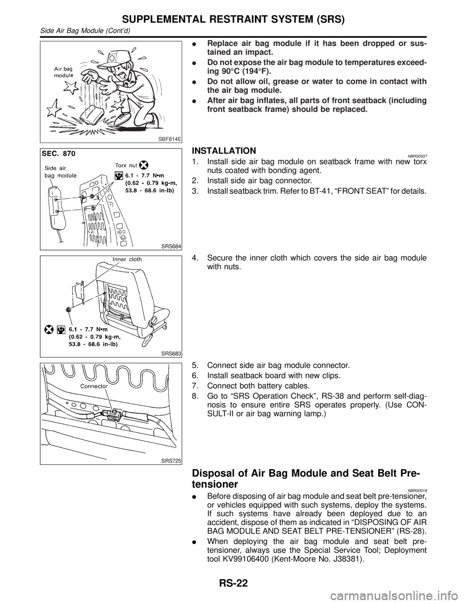
IReplace air bag module if it has been dropped or sus-
tained an impact.
IDo not expose the air bag module to temperatures exceed-
ing 90ÉC (194ÉF).
IDo not allow oil, grease or water to come in contact with
the air bag module.
IAfter air bag inflates, all parts of front seatback (including
front seatback frame) should be replaced.
SRS684
INSTALLATIONNBRS00371. Install side air bag module on seatback frame with new torx
nuts coated with bonding agent.
2. Install side air bag connector.
3. Install seatback trim. Refer to BT-41, ªFRONT SEATº for details.
SRS683
4. Secure the inner cloth which covers the side air bag module
with nuts.
SRS725
5. Connect side air bag module connector.
6. Install seatback board with new clips.
7. Connect both battery cables.
8. Go to ªSRS Operation Checkº, RS-38 and perform self-diag-
nosis to ensure entire SRS operates properly. (Use CON-
SULT-II or air bag warning lamp.)
Disposal of Air Bag Module and Seat Belt Pre-
tensioner
NBRS0018IBefore disposing of air bag module and seat belt pre-tensioner,
or vehicles equipped with such systems, deploy the systems.
If such systems have already been deployed due to an
accident, dispose of them as indicated in ªDISPOSING OF AIR
BAG MODULE AND SEAT BELT PRE-TENSIONERº (RS-28).
IWhen deploying the air bag module and seat belt pre-
tensioner, always use the Special Service Tool; Deployment
tool KV99106400 (Kent-Moore No. J38381).
SUPPLEMENTAL RESTRAINT SYSTEM (SRS)
Side Air Bag Module (Cont'd)
RS-22
Page 2182 of 2395
STEERING SYSTEM
SECTION
ST
CONTENTS
PRECAUTIONS...............................................................2
Supplemental Restraint System (SRS)²AIR
BAG²and²SEAT BELT PRE-TENSIONER²...............2
Precautions for Steering System .................................2
PREPARATION...............................................................3
Special Service Tools ..................................................3
Commercial Service Tools ...........................................5
NOISE, VIBRATION AND HARSHNESS (NVH)
TROUBLESHOOTING.....................................................6
NVH Troubleshooting Chart.........................................6
ON-VEHICLE SERVICE..................................................7
Checking Steering Wheel Play ....................................7
Checking Neutral Position on Steering Wheel ............7
PRE-CHECKING........................................................7
CHECKING...............................................................7
Front Wheel Turning Angle ..........................................7
Checking Gear Housing Movement ............................8
Adjusting Rack Retainer ..............................................8
Checking and Adjusting Drive Belts ............................8
Checking Fluid Level ...................................................8
Checking Fluid Leakage ..............................................8
Bleeding Hydraulic System..........................................9
Checking Steering Wheel Turning Force ....................9
Checking Hydraulic System.......................................10
STEERING WHEEL AND STEERING COLUMN......... 11
Components............................................................... 11
Removal and Installation ........................................... 11
STEERING WHEEL................................................. 11
STEERING COLUMN...............................................12
Disassembly and Assembly .......................................13
Inspection...................................................................14
TILT MECHANISM...................................................14
STEERING TRANSFER GEAR.....................................15
Removal .....................................................................15
Installation ..................................................................16
Inspection...................................................................16
POWER STEERING GEAR AND LINKAGE................17
Components...............................................................17
Removal and Installation ...........................................18
Disassembly...............................................................19
Inspection...................................................................20
BOOT.....................................................................20
RACK.....................................................................20
PINION ASSEMBLY.................................................20
GEAR HOUSING CYLINDER....................................20
TIE-ROD OUTER AND INNER SOCKETS..................21
Assembly ...................................................................21
Adjustment .................................................................24
POWER STEERING OIL PUMP....................................27
Components...............................................................27
Pre-disassembly Inspection .......................................27
Disassembly...............................................................28
Inspection...................................................................29
Assembly ...................................................................29
SERVICE DATA AND SPECIFICATIONS (SDS).........32
General Specifications ...............................................32
Steering Wheel ..........................................................32
Steering Column ........................................................32
Steering Transfer Gear ..............................................32
Steering Gear and Linkage .......................................33
Power Steering ..........................................................33
GI
MA
EM
LC
EC
FE
AT
TF
PD
AX
SU
BR
RS
BT
HA
SC
EL
IDX
Page 2189 of 2395
SST601C
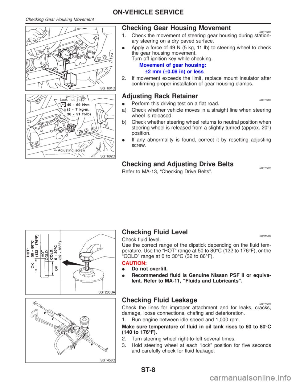
Checking Gear Housing MovementNBST00081. Check the movement of steering gear housing during station-
ary steering on a dry paved surface.
IApply a force of 49 N (5 kg, 11 lb) to steering wheel to check
the gear housing movement.
Turn off ignition key while checking.
Movement of gear housing:
±2mm(±0.08 in) or less
2. If movement exceeds the limit, replace mount insulator after
confirming proper installation of gear housing clamps.
SST602C
Adjusting Rack RetainerNBST0009IPerform this driving test on a flat road.
a) Check whether vehicle moves in a straight line when steering
wheel is released.
b) Check whether steering wheel returns to neutral position when
steering wheel is released from a slightly turned (approx. 20É)
position.
IIf any abnormality is found, correct it by resetting adjusting
screw.
Checking and Adjusting Drive BeltsNBST0010Refer to MA-13, ªChecking Drive Beltsº.
SST280BA
Checking Fluid LevelNBST0011Check fluid level.
Use the correct range of the dipstick depending on the fluid tem-
perature. Use the ªHOTº range at 50 to 80ÉC (122 to 176ÉF), or the
ªCOLDº range at 0 to 30ÉC (32 to 86ÉF).
CAUTION:
IDo not overfill.
IRecommended fluid is Genuine Nissan PSF II or equiva-
lent. Refer to MA-11, ªFluids and Lubricantsº.
SST458C
Checking Fluid LeakageNBST0012Check the lines for improper attachment and for leaks, cracks,
damage, loose connections, chafing and deterioration.
1. Run engine between idle speed and 1,000 rpm.
Make sure temperature of fluid in oil tank rises to 60 to 80ÉC
(140 to 176ÉF).
2. Turn steering wheel right-to-left several times.
3. Hold steering wheel at each ªlockº position for five seconds
and carefully check for fluid leakage.
ON-VEHICLE SERVICE
Checking Gear Housing Movement
ST-8
Page 2190 of 2395
CAUTION:
Do not hold the steering wheel in a locked position for more
than 15 seconds.
4. If fluid leakage at connectors is noticed, loosen flare nut and
then retighten.
Do not overtighten connector as this can damage O-ring,
washer and connector.
5. Check rack boots for accumulation of power steering fluid.
Bleeding Hydraulic SystemNBST00131. Raise front end of vehicle until wheels are clear of the ground.
2. Add fluid into oil tank to specified level. Then, quickly turn
steering wheel fully to right and left and lightly touch steering
stoppers.
Repeat steering wheel operation until fluid level no longer
decreases.
3. Start engine.
Repeat step 2 above.
IIncomplete air bleeding will cause the following to occur. When
this happens, bleed air again.
a) Air bubbles in reservoir tank
b) Clicking noise in oil pump
c) Excessive buzzing in oil pump
Fluid noise may occur in the valve or oil pump. This is common
when the vehicle is stationary or while turning steering wheel
slowly. This does not affect performance or durability of the system.
SST491B
SST090B
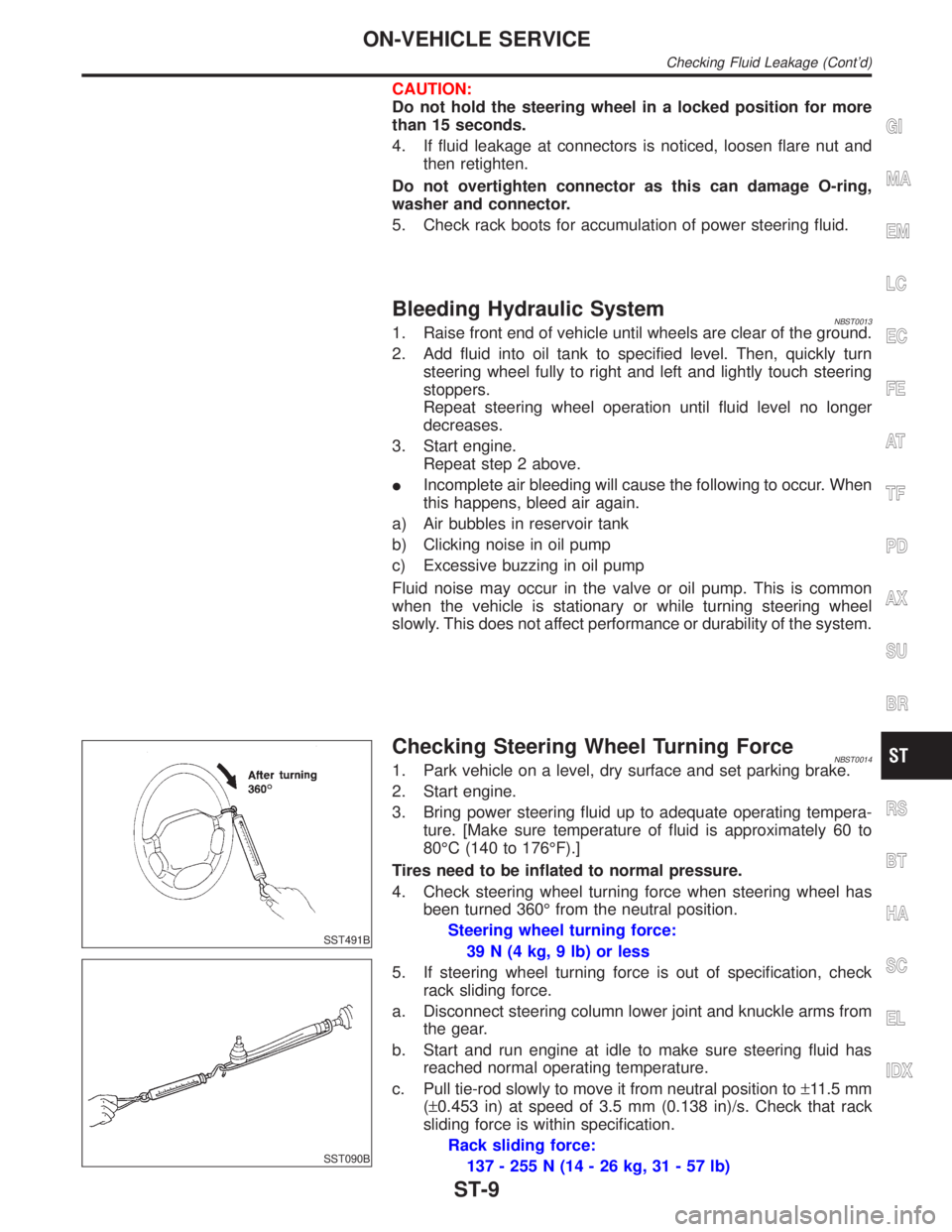
Checking Steering Wheel Turning ForceNBST00141. Park vehicle on a level, dry surface and set parking brake.
2. Start engine.
3. Bring power steering fluid up to adequate operating tempera-
ture. [Make sure temperature of fluid is approximately 60 to
80ÉC (140 to 176ÉF).]
Tires need to be inflated to normal pressure.
4. Check steering wheel turning force when steering wheel has
been turned 360É from the neutral position.
Steering wheel turning force:
39 N (4 kg, 9 lb) or less
5. If steering wheel turning force is out of specification, check
rack sliding force.
a. Disconnect steering column lower joint and knuckle arms from
the gear.
b. Start and run engine at idle to make sure steering fluid has
reached normal operating temperature.
c. Pull tie-rod slowly to move it from neutral position to±11.5 mm
(±0.453 in) at speed of 3.5 mm (0.138 in)/s. Check that rack
sliding force is within specification.
Rack sliding force:
137 - 255 N (14 - 26 kg, 31 - 57 lb)
GI
MA
EM
LC
EC
FE
AT
TF
PD
AX
SU
BR
RS
BT
HA
SC
EL
IDX
ON-VEHICLE SERVICE
Checking Fluid Leakage (Cont'd)
ST-9
Page 2201 of 2395
SST051C
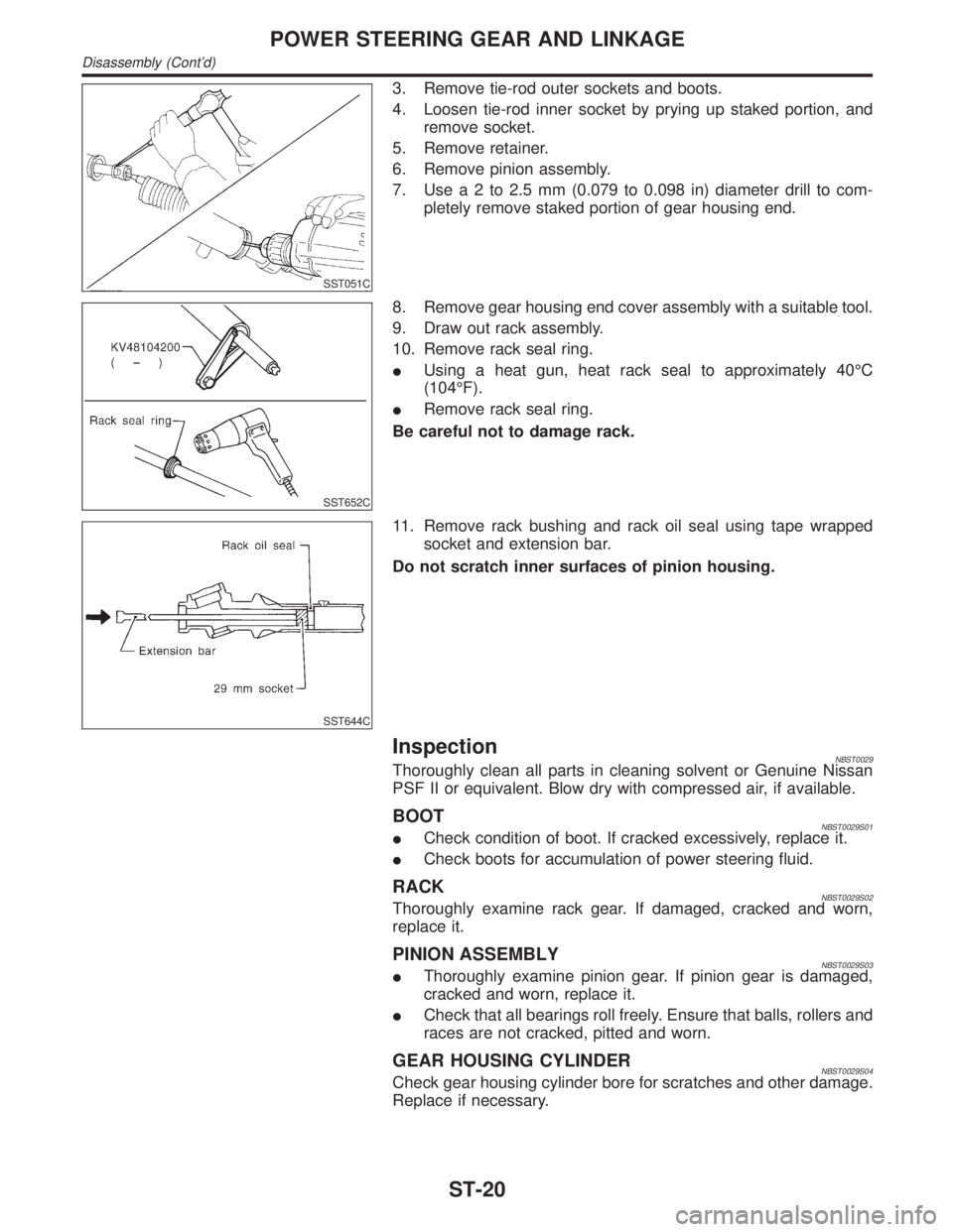
3. Remove tie-rod outer sockets and boots.
4. Loosen tie-rod inner socket by prying up staked portion, and
remove socket.
5. Remove retainer.
6. Remove pinion assembly.
7. Usea2to2.5mm(0.079 to 0.098 in) diameter drill to com-
pletely remove staked portion of gear housing end.
SST652C
8. Remove gear housing end cover assembly with a suitable tool.
9. Draw out rack assembly.
10. Remove rack seal ring.
IUsing a heat gun, heat rack seal to approximately 40ÉC
(104ÉF).
IRemove rack seal ring.
Be careful not to damage rack.
SST644C
11. Remove rack bushing and rack oil seal using tape wrapped
socket and extension bar.
Do not scratch inner surfaces of pinion housing.
InspectionNBST0029Thoroughly clean all parts in cleaning solvent or Genuine Nissan
PSF II or equivalent. Blow dry with compressed air, if available.
BOOTNBST0029S01ICheck condition of boot. If cracked excessively, replace it.
ICheck boots for accumulation of power steering fluid.
RACKNBST0029S02Thoroughly examine rack gear. If damaged, cracked and worn,
replace it.
PINION ASSEMBLYNBST0029S03IThoroughly examine pinion gear. If pinion gear is damaged,
cracked and worn, replace it.
ICheck that all bearings roll freely. Ensure that balls, rollers and
races are not cracked, pitted and worn.
GEAR HOUSING CYLINDERNBST0029S04Check gear housing cylinder bore for scratches and other damage.
Replace if necessary.
POWER STEERING GEAR AND LINKAGE
Disassembly (Cont'd)
ST-20
Page 2202 of 2395
SST468C
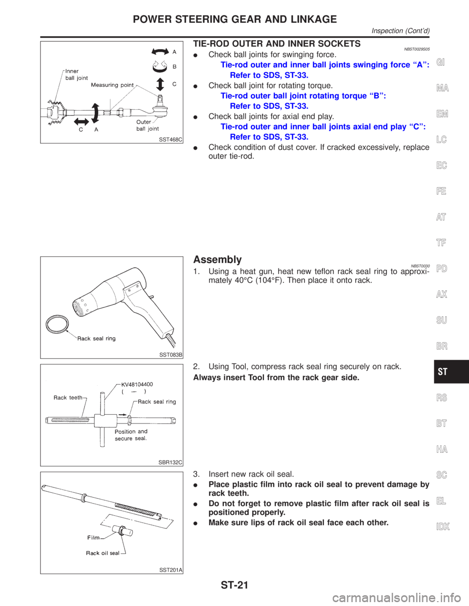
TIE-ROD OUTER AND INNER SOCKETSNBST0029S05ICheck ball joints for swinging force.
Tie-rod outer and inner ball joints swinging force ªAº:
Refer to SDS, ST-33.
ICheck ball joint for rotating torque.
Tie-rod outer ball joint rotating torque ªBº:
Refer to SDS, ST-33.
ICheck ball joints for axial end play.
Tie-rod outer and inner ball joints axial end play ªCº:
Refer to SDS, ST-33.
ICheck condition of dust cover. If cracked excessively, replace
outer tie-rod.
SST083B
AssemblyNBST00301. Using a heat gun, heat new teflon rack seal ring to approxi-
mately 40ÉC (104ÉF). Then place it onto rack.
SBR132C
2. Using Tool, compress rack seal ring securely on rack.
Always insert Tool from the rack gear side.
SST201A
3. Insert new rack oil seal.
IPlace plastic film into rack oil seal to prevent damage by
rack teeth.
IDo not forget to remove plastic film after rack oil seal is
positioned properly.
IMake sure lips of rack oil seal face each other.
GI
MA
EM
LC
EC
FE
AT
TF
PD
AX
SU
BR
RS
BT
HA
SC
EL
IDX
POWER STEERING GEAR AND LINKAGE
Inspection (Cont'd)
ST-21
Page 2210 of 2395
InspectionNBST0035IIf pulley is cracked or deformed, replace it.
IIf an oil leak is found around pulley shaft oil seal, replace the
seal.
ICheck the casing and the inside of the rear body for damage.
If damages are found in the rear body, replace the entire rear
body. If the casing is damaged, replace the entire power steer-
ing pump as an assembly.
ICheck the cam ring for damage. If damage is found, replace
the cam ring, rotor and vane as a set.
ICheck the side plates (front and rear) for damage. If damage
is found, replace the side plates as a set (front and rear).
SST934C
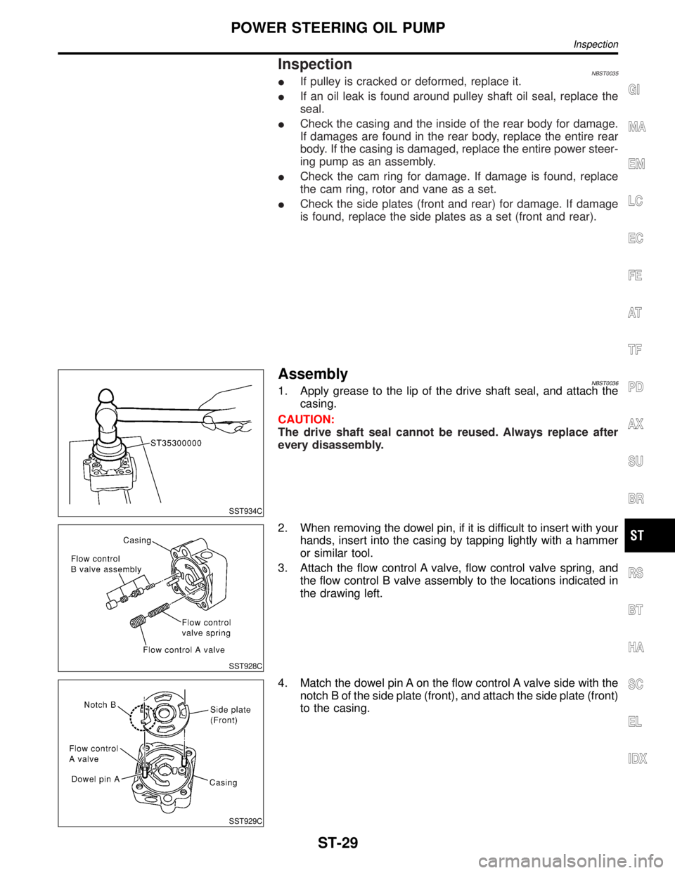
AssemblyNBST00361. Apply grease to the lip of the drive shaft seal, and attach the
casing.
CAUTION:
The drive shaft seal cannot be reused. Always replace after
every disassembly.
SST928C
2. When removing the dowel pin, if it is difficult to insert with your
hands, insert into the casing by tapping lightly with a hammer
or similar tool.
3. Attach the flow control A valve, flow control valve spring, and
the flow control B valve assembly to the locations indicated in
the drawing left.
SST929C
4. Match the dowel pin A on the flow control A valve side with the
notch B of the side plate (front), and attach the side plate (front)
to the casing.
GI
MA
EM
LC
EC
FE
AT
TF
PD
AX
SU
BR
RS
BT
HA
SC
EL
IDX
POWER STEERING OIL PUMP
Inspection
ST-29
Page 2217 of 2395
SBR686C
Precautions
PRECAUTIONSNBSU0001IWhen installing rubber parts, final tightening must be car-
ried out under unladen condition* with tires on ground.
*Fuel, radiator coolant and engine oil full. Spare tire, jack,
hand tools and mats in designated positions.
IUse flare nut wrench when removing and installing brake
tubes.
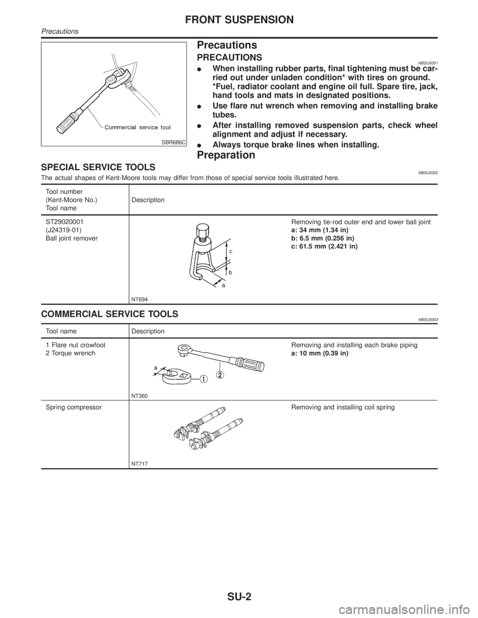
IAfter installing removed suspension parts, check wheel
alignment and adjust if necessary.
IAlways torque brake lines when installing.
Preparation
SPECIAL SERVICE TOOLSNBSU0002The actual shapes of Kent-Moore tools may differ from those of special service tools illustrated here.
Tool number
(Kent-Moore No.)
Tool nameDescription
ST29020001
(J24319-01)
Ball joint remover
NT694
Removing tie-rod outer end and lower ball joint
a: 34 mm (1.34 in)
b: 6.5 mm (0.256 in)
c: 61.5 mm (2.421 in)
COMMERCIAL SERVICE TOOLSNBSU0003
Tool name Description
1 Flare nut crowfoot
2 Torque wrench
NT360
Removing and installing each brake piping
a: 10 mm (0.39 in)
Spring compressor
NT717
Removing and installing coil spring
FRONT SUSPENSION
Precautions
SU-2