2001 INFINITI QX4 check oil
[x] Cancel search: check oilPage 2026 of 2395
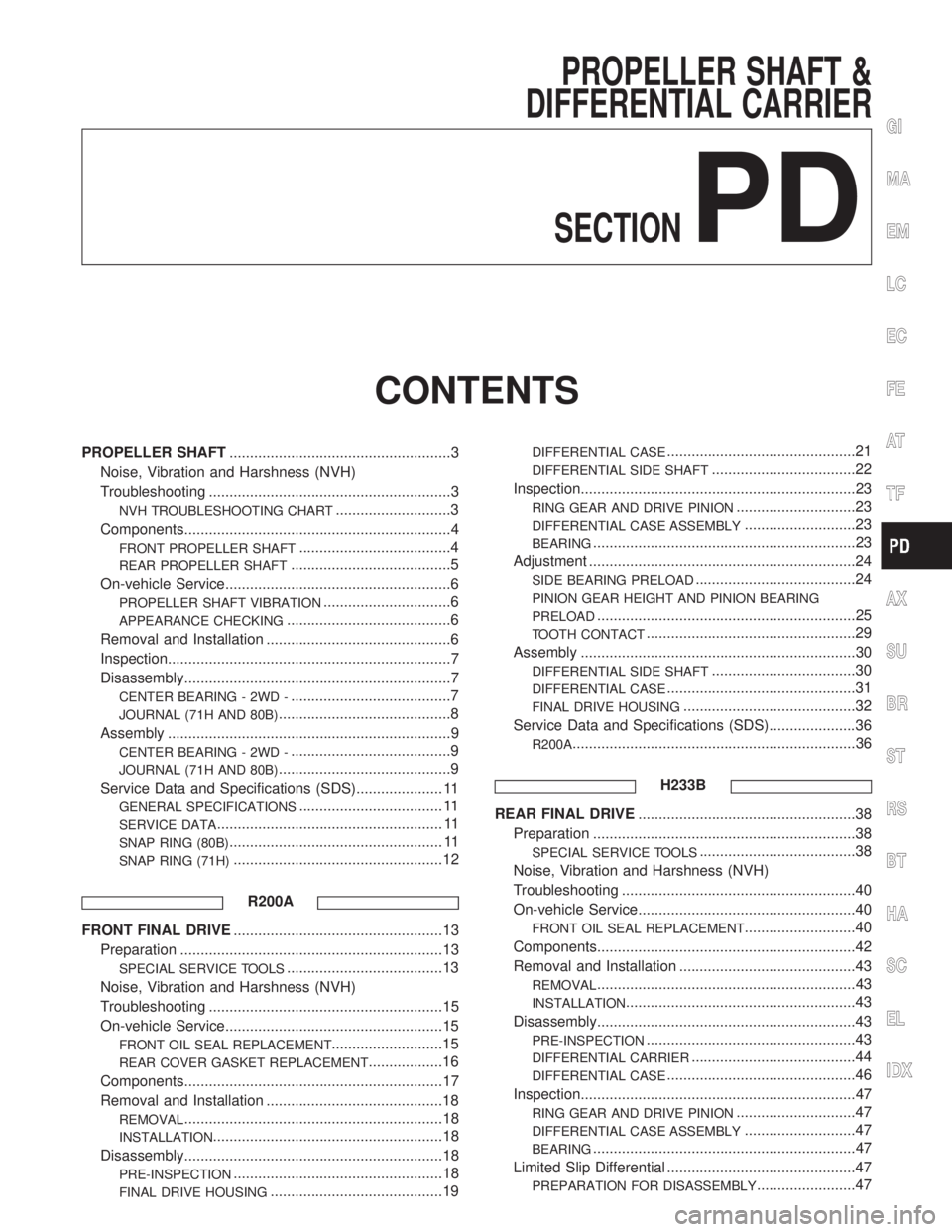
PROPELLER SHAFT &
DIFFERENTIAL CARRIER
SECTION
PD
CONTENTS
PROPELLER SHAFT......................................................3
Noise, Vibration and Harshness (NVH)
Troubleshooting ...........................................................3
NVH TROUBLESHOOTING CHART............................3
Components.................................................................4
FRONT PROPELLER SHAFT.....................................4
REAR PROPELLER SHAFT.......................................5
On-vehicle Service.......................................................6
PROPELLER SHAFT VIBRATION...............................6
APPEARANCE CHECKING........................................6
Removal and Installation .............................................6
Inspection.....................................................................7
Disassembly.................................................................7
CENTER BEARING - 2WD -.......................................7
JOURNAL (71H AND 80B)..........................................8
Assembly .....................................................................9
CENTER BEARING - 2WD -.......................................9
JOURNAL (71H AND 80B)..........................................9
Service Data and Specifications (SDS)..................... 11
GENERAL SPECIFICATIONS................................... 11
SERVICE DATA....................................................... 11
SNAP RING (80B).................................................... 11
SNAP RING (71H)...................................................12
R200A
FRONT FINAL DRIVE...................................................13
Preparation ................................................................13
SPECIAL SERVICE TOOLS......................................13
Noise, Vibration and Harshness (NVH)
Troubleshooting .........................................................15
On-vehicle Service.....................................................15
FRONT OIL SEAL REPLACEMENT...........................15
REAR COVER GASKET REPLACEMENT..................16
Components...............................................................17
Removal and Installation ...........................................18
REMOVAL...............................................................18
INSTALLATION........................................................18
Disassembly...............................................................18
PRE-INSPECTION...................................................18
FINAL DRIVE HOUSING..........................................19
DIFFERENTIAL CASE..............................................21
DIFFERENTIAL SIDE SHAFT...................................22
Inspection...................................................................23
RING GEAR AND DRIVE PINION.............................23
DIFFERENTIAL CASE ASSEMBLY...........................23
BEARING................................................................23
Adjustment .................................................................24
SIDE BEARING PRELOAD.......................................24
PINION GEAR HEIGHT AND PINION BEARING
PRELOAD
...............................................................25
TOOTH CONTACT...................................................29
Assembly ...................................................................30
DIFFERENTIAL SIDE SHAFT...................................30
DIFFERENTIAL CASE..............................................31
FINAL DRIVE HOUSING..........................................32
Service Data and Specifications (SDS).....................36
R200A.....................................................................36
H233B
REAR FINAL DRIVE.....................................................38
Preparation ................................................................38
SPECIAL SERVICE TOOLS......................................38
Noise, Vibration and Harshness (NVH)
Troubleshooting .........................................................40
On-vehicle Service.....................................................40
FRONT OIL SEAL REPLACEMENT...........................40
Components...............................................................42
Removal and Installation ...........................................43
REMOVAL...............................................................43
INSTALLATION........................................................43
Disassembly...............................................................43
PRE-INSPECTION...................................................43
DIFFERENTIAL CARRIER........................................44
DIFFERENTIAL CASE..............................................46
Inspection...................................................................47
RING GEAR AND DRIVE PINION.............................47
DIFFERENTIAL CASE ASSEMBLY...........................47
BEARING................................................................47
Limited Slip Differential ..............................................47
PREPARATION FOR DISASSEMBLY........................47
GI
MA
EM
LC
EC
FE
AT
TF
AX
SU
BR
ST
RS
BT
HA
SC
EL
IDX
Page 2043 of 2395
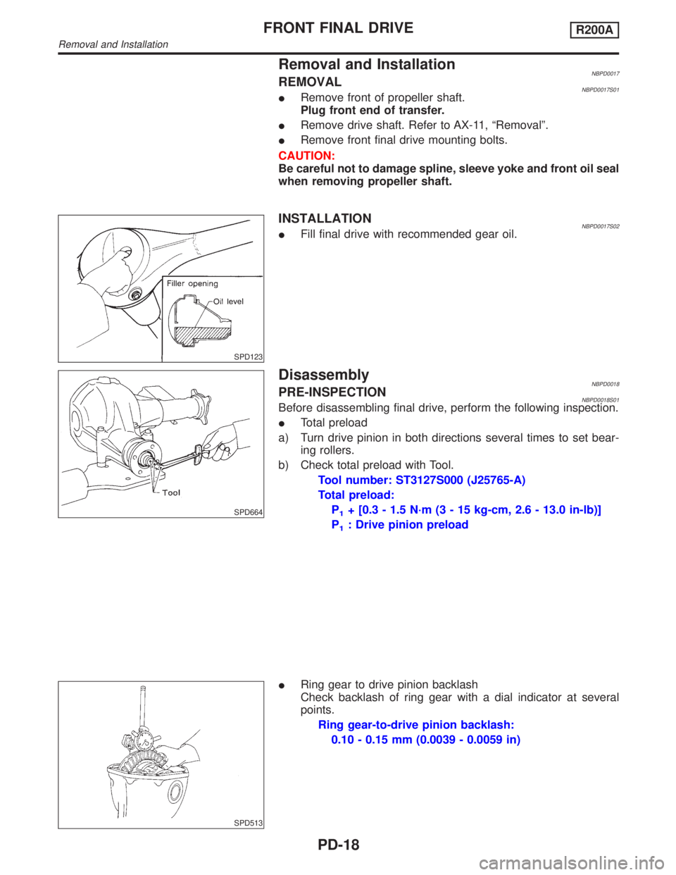
Removal and InstallationNBPD0017REMOVALNBPD0017S01IRemove front of propeller shaft.
Plug front end of transfer.
IRemove drive shaft. Refer to AX-11, ªRemovalº.
IRemove front final drive mounting bolts.
CAUTION:
Be careful not to damage spline, sleeve yoke and front oil seal
when removing propeller shaft.
SPD123
INSTALLATIONNBPD0017S02IFill final drive with recommended gear oil.
SPD664
DisassemblyNBPD0018PRE-INSPECTIONNBPD0018S01Before disassembling final drive, perform the following inspection.
ITotal preload
a) Turn drive pinion in both directions several times to set bear-
ing rollers.
b) Check total preload with Tool.
Tool number: ST3127S000 (J25765-A)
Total preload:
P
1+ [0.3 - 1.5 N´m (3 - 15 kg-cm, 2.6 - 13.0 in-lb)]
P
1: Drive pinion preload
SPD513
IRing gear to drive pinion backlash
Check backlash of ring gear with a dial indicator at several
points.
Ring gear-to-drive pinion backlash:
0.10 - 0.15 mm (0.0039 - 0.0059 in)
FRONT FINAL DRIVER200A
Removal and Installation
PD-18
Page 2048 of 2395
SPD647
SPD781
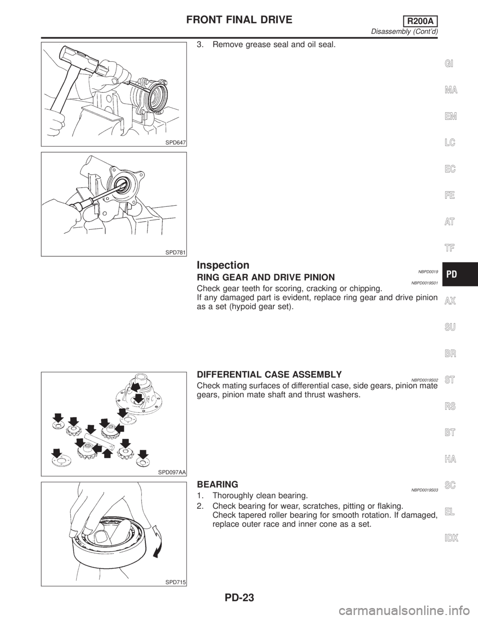
3. Remove grease seal and oil seal.
InspectionNBPD0019RING GEAR AND DRIVE PINIONNBPD0019S01Check gear teeth for scoring, cracking or chipping.
If any damaged part is evident, replace ring gear and drive pinion
as a set (hypoid gear set).
SPD097AA
DIFFERENTIAL CASE ASSEMBLYNBPD0019S02Check mating surfaces of differential case, side gears, pinion mate
gears, pinion mate shaft and thrust washers.
SPD715
BEARINGNBPD0019S031. Thoroughly clean bearing.
2. Check bearing for wear, scratches, pitting or flaking.
Check tapered roller bearing for smooth rotation. If damaged,
replace outer race and inner cone as a set.
GI
MA
EM
LC
EC
FE
AT
TF
AX
SU
BR
ST
RS
BT
HA
SC
EL
IDX
FRONT FINAL DRIVER200A
Disassembly (Cont'd)
PD-23
Page 2054 of 2395
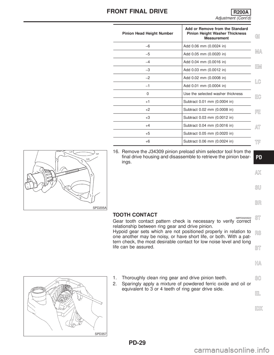
Pinion Head Height NumberAdd or Remove from the Standard
Pinion Height Washer Thickness
Measurement
þ6 Add 0.06 mm (0.0024 in)
þ5 Add 0.05 mm (0.0020 in)
þ4 Add 0.04 mm (0.0016 in)
þ3 Add 0.03 mm (0.0012 in)
þ2 Add 0.02 mm (0.0008 in)
þ1 Add 0.01 mm (0.0004 in)
0 Use the selected washer thickness
+1 Subtract 0.01 mm (0.0004 in)
+2 Subtract 0.02 mm (0.0008 in)
+3 Subtract 0.03 mm (0.0012 in)
+4 Subtract 0.04 mm (0.0016 in)
+5 Subtract 0.05 mm (0.0020 in)
+6 Subtract 0.06 mm (0.0024 in)
SPD205A
16. Remove the J34309 pinion preload shim selector tool from the
final drive housing and disassemble to retrieve the pinion bear-
ings.
TOOTH CONTACTNBPD0020S03Gear tooth contact pattern check is necessary to verify correct
relationship between ring gear and drive pinion.
Hypoid gear sets which are not positioned properly in relation to
one another may be noisy, or have short life, or both. With a pat-
tern check, the most desirable contact for low noise level and long
life can be assured.
SPD357
1. Thoroughly clean ring gear and drive pinion teeth.
2. Sparingly apply a mixture of powdered ferric oxide and oil or
equivalent to 3 or 4 teeth of ring gear drive side.
GI
MA
EM
LC
EC
FE
AT
TF
AX
SU
BR
ST
RS
BT
HA
SC
EL
IDX
FRONT FINAL DRIVER200A
Adjustment (Cont'd)
PD-29
Page 2056 of 2395
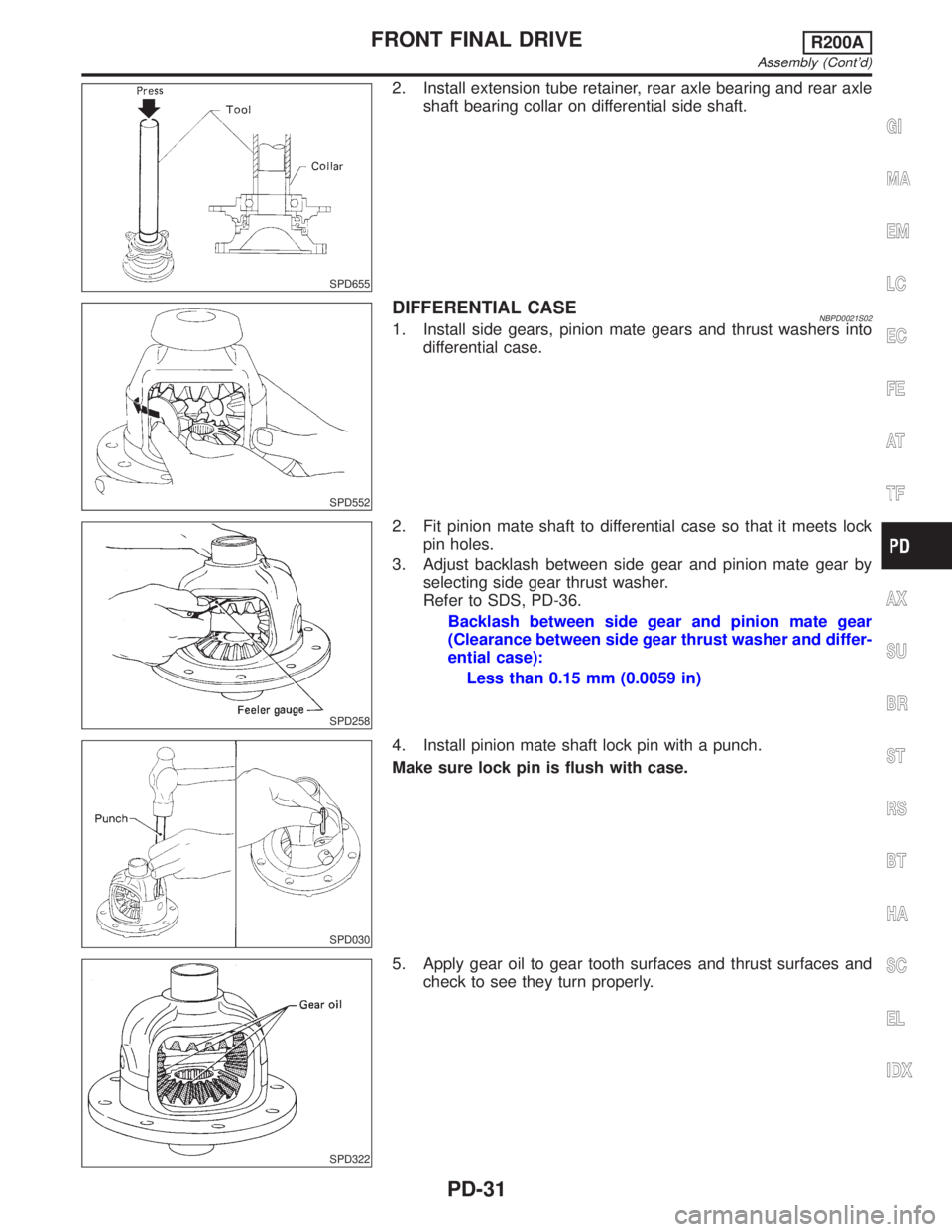
SPD655
2. Install extension tube retainer, rear axle bearing and rear axle
shaft bearing collar on differential side shaft.
SPD552
DIFFERENTIAL CASENBPD0021S021. Install side gears, pinion mate gears and thrust washers into
differential case.
SPD258
2. Fit pinion mate shaft to differential case so that it meets lock
pin holes.
3. Adjust backlash between side gear and pinion mate gear by
selecting side gear thrust washer.
Refer to SDS, PD-36.
Backlash between side gear and pinion mate gear
(Clearance between side gear thrust washer and differ-
ential case):
Less than 0.15 mm (0.0059 in)
SPD030
4. Install pinion mate shaft lock pin with a punch.
Make sure lock pin is flush with case.
SPD322
5. Apply gear oil to gear tooth surfaces and thrust surfaces and
check to see they turn properly.
GI
MA
EM
LC
EC
FE
AT
TF
AX
SU
BR
ST
RS
BT
HA
SC
EL
IDX
FRONT FINAL DRIVER200A
Assembly (Cont'd)
PD-31
Page 2060 of 2395
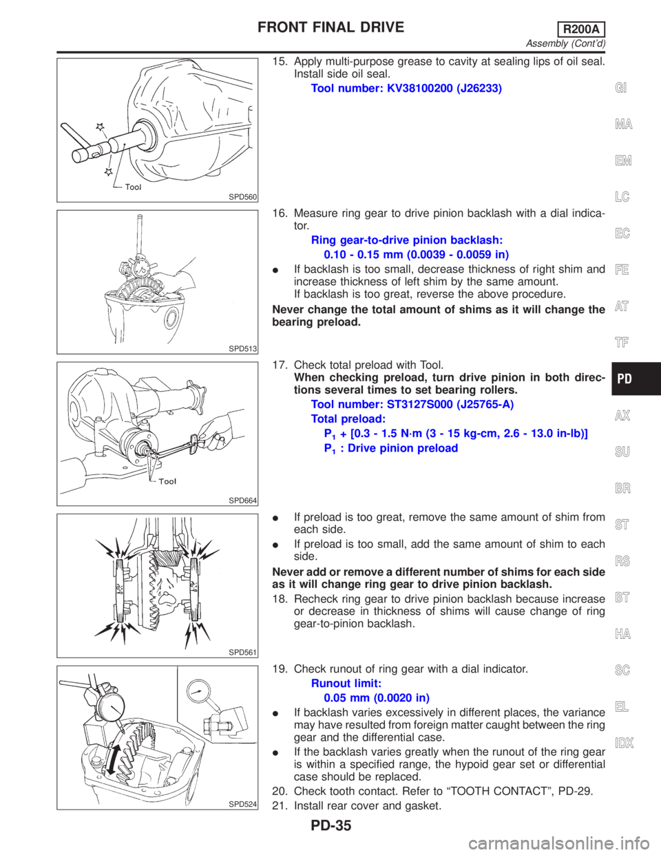
SPD560
15. Apply multi-purpose grease to cavity at sealing lips of oil seal.
Install side oil seal.
Tool number: KV38100200 (J26233)
SPD513
16. Measure ring gear to drive pinion backlash with a dial indica-
tor.
Ring gear-to-drive pinion backlash:
0.10 - 0.15 mm (0.0039 - 0.0059 in)
IIf backlash is too small, decrease thickness of right shim and
increase thickness of left shim by the same amount.
If backlash is too great, reverse the above procedure.
Never change the total amount of shims as it will change the
bearing preload.
SPD664
17. Check total preload with Tool.
When checking preload, turn drive pinion in both direc-
tions several times to set bearing rollers.
Tool number: ST3127S000 (J25765-A)
Total preload:
P
1+ [0.3 - 1.5 N´m (3 - 15 kg-cm, 2.6 - 13.0 in-lb)]
P
1: Drive pinion preload
SPD561
IIf preload is too great, remove the same amount of shim from
each side.
IIf preload is too small, add the same amount of shim to each
side.
Never add or remove a different number of shims for each side
as it will change ring gear to drive pinion backlash.
18. Recheck ring gear to drive pinion backlash because increase
or decrease in thickness of shims will cause change of ring
gear-to-pinion backlash.
SPD524
19. Check runout of ring gear with a dial indicator.
Runout limit:
0.05 mm (0.0020 in)
IIf backlash varies excessively in different places, the variance
may have resulted from foreign matter caught between the ring
gear and the differential case.
IIf the backlash varies greatly when the runout of the ring gear
is within a specified range, the hypoid gear set or differential
case should be replaced.
20. Check tooth contact. Refer to ªTOOTH CONTACTº, PD-29.
21. Install rear cover and gasket.
GI
MA
EM
LC
EC
FE
AT
TF
AX
SU
BR
ST
RS
BT
HA
SC
EL
IDX
FRONT FINAL DRIVER200A
Assembly (Cont'd)
PD-35
Page 2061 of 2395
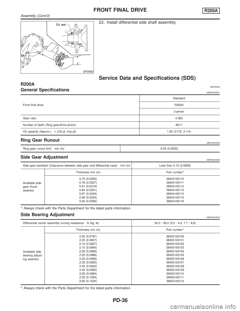
SPD682
22. Install differential side shaft assembly.
Service Data and Specifications (SDS)
R200ANBPD0022General SpecificationsNBPD0022S01
Front final driveStandard
R200A
2-pinion
Gear ratio4.363
Number of teeth (Ring gear/drive pinion)48/11
Oil capacity (Approx.)(US pt, lmp pt) 1.85 (3-7/8, 3-1/4)
Ring Gear RunoutNBPD0022S02
Ring gear runout limit mm (in)0.05 (0.0020)
Side Gear AdjustmentNBPD0022S03
Side gear backlash (Clearance between side gear and differential case) mm (in) Less than 0.15 (0.0059)
Available side
gear thrust
washersThickness mm (in) Part number*
0.75 (0.0295)
0.78 (0.0307)
0.81 (0.0319)
0.84 (0.0331)
0.87 (0.0343)
0.90 (0.0354)
0.93 (0.0366)38424-N3110
38424-N3111
38424-N3112
38424-N3113
38424-N3114
38424-N3115
38424-N3116
*: Always check with the Parts Department for the latest parts information.
Side Bearing AdjustmentNBPD0022S04
Differential carrier assembly turning resistance N (kg, lb) 34.3 - 39.2 (3.5 - 4.0, 7.7 - 8.8)
Available side
bearing adjust-
ing washersThickness mm (in) Part number*
2.00 (0.0787)
2.05 (0.0807)
2.10 (0.0827)
2.15 (0.0846)
2.20 (0.0866)
2.25 (0.0886)
2.30 (0.0906)
2.35 (0.0925)
2.40 (0.0945)
2.45 (0.0965)
2.50 (0.0984)
2.55 (0.1004)
2.60 (0.1024)38453-N3100
38453-N3101
38453-N3102
38453-N3103
38453-N3104
38453-N3105
38453-N3106
38453-N3107
38453-N3108
38453-N3109
38453-N3110
38453-N3111
38453-N3112
*: Always check with the Parts Department for the latest parts information.
FRONT FINAL DRIVER200A
Assembly (Cont'd)
PD-36
Page 2062 of 2395
![INFINITI QX4 2001 Factory Service Manual Total Preload AdjustmentNBPD0022S05
Total preload N´m (kg-cm, in-lb) P1+ [0.3 - 1.5 (3 - 15, 2.6 - 13.0)]
Ring gear backlash mm (in) 0.10 - 0.15 (0.0039 - 0.0059)
P1: Drive pinion preload
Drive Pinio INFINITI QX4 2001 Factory Service Manual Total Preload AdjustmentNBPD0022S05
Total preload N´m (kg-cm, in-lb) P1+ [0.3 - 1.5 (3 - 15, 2.6 - 13.0)]
Ring gear backlash mm (in) 0.10 - 0.15 (0.0039 - 0.0059)
P1: Drive pinion preload
Drive Pinio](/manual-img/42/57027/w960_57027-2061.png)
Total Preload AdjustmentNBPD0022S05
Total preload N´m (kg-cm, in-lb) P1+ [0.3 - 1.5 (3 - 15, 2.6 - 13.0)]
Ring gear backlash mm (in) 0.10 - 0.15 (0.0039 - 0.0059)
P1: Drive pinion preload
Drive Pinion Height AdjustmentNBPD0022S06
Available pin-
ion height
adjusting
washersThickness mm (in) Part number*
3.09 (0.1217)
3.12 (0.1228)
3.15 (0.1240)
3.18 (0.1252)
3.21 (0.1264)
3.24 (0.1276)
3.27 (0.1287)
3.30 (0.1299)
3.33 (0.1311)
3.36 (0.1323)
3.39 (0.1335)
3.42 (0.1346)
3.45 (0.1358)
3.48 (0.1370)
3.51 (0.1382)
3.54 (0.1394)
3.57 (0.1406)
3.60 (0.1417)
3.63 (0.1429)
3.66 (0.1441)38154-P6017
38154-P6018
38154-P6019
38154-P6020
38154-P6021
38154-P6022
38154-P6023
38154-P6024
38154-P6025
38154-P6026
38154-P6027
38154-P6028
38154-P6029
38154-P6030
38154-P6031
38154-P6032
38154-P6033
38154-P6034
38154-P6035
38154-P6036
*: Always check with the Parts Department for the latest parts information.
Drive Pinion Preload AdjustmentNBPD0022S07
Drive pinion bearing preload adjusting method Adjusting washer and spacer
Drive pinion preload with front oil seal N´m (kg-cm, in-lb) [P
1] 1.1 - 1.4 (11 - 14, 9.5 - 12.2)
Available drive
pinion bearing
preload adjust-
ing washersThickness mm (in) Part number*
3.81 (0.1500)
3.83 (0.1508)
3.85 (0.1516)
3.87 (0.1524)
3.89 (0.1531)
3.91 (0.1539)
3.93 (0.1547)
3.95 (0.1555)
3.97 (0.1563)
3.99 (0.1571)
4.01 (0.1579)
4.03 (0.1587)
4.05 (0.1594)
4.07 (0.1602)
4.09 (0.1610)38125-61001
38126-61001
38127-61001
38128-61001
38129-61001
38130-61001
38131-61001
38132-61001
38133-61001
38134-61001
38135-61001
38136-61001
38137-61001
38138-61001
38139-61001
Available drive
pinion bearing
preload adjust-
ing spacersLength mm (in) Part number*
54.50 (2.1457)
54.80 (2.1575)
55.10 (2.1693)
55.40 (2.1811)
55.70 (2.1929)
56.00 (2.2047)38165-B4000
38165-B4001
38165-B4002
38165-B4003
38165-B4004
38165-61001
*: Always check with the Parts Department for the latest parts information.
GI
MA
EM
LC
EC
FE
AT
TF
AX
SU
BR
ST
RS
BT
HA
SC
EL
IDX
FRONT FINAL DRIVER200A
Service Data and Specifications (SDS) (Cont'd)
PD-37