Page 2312 of 2395
4 CHECK INPUT SIGNAL
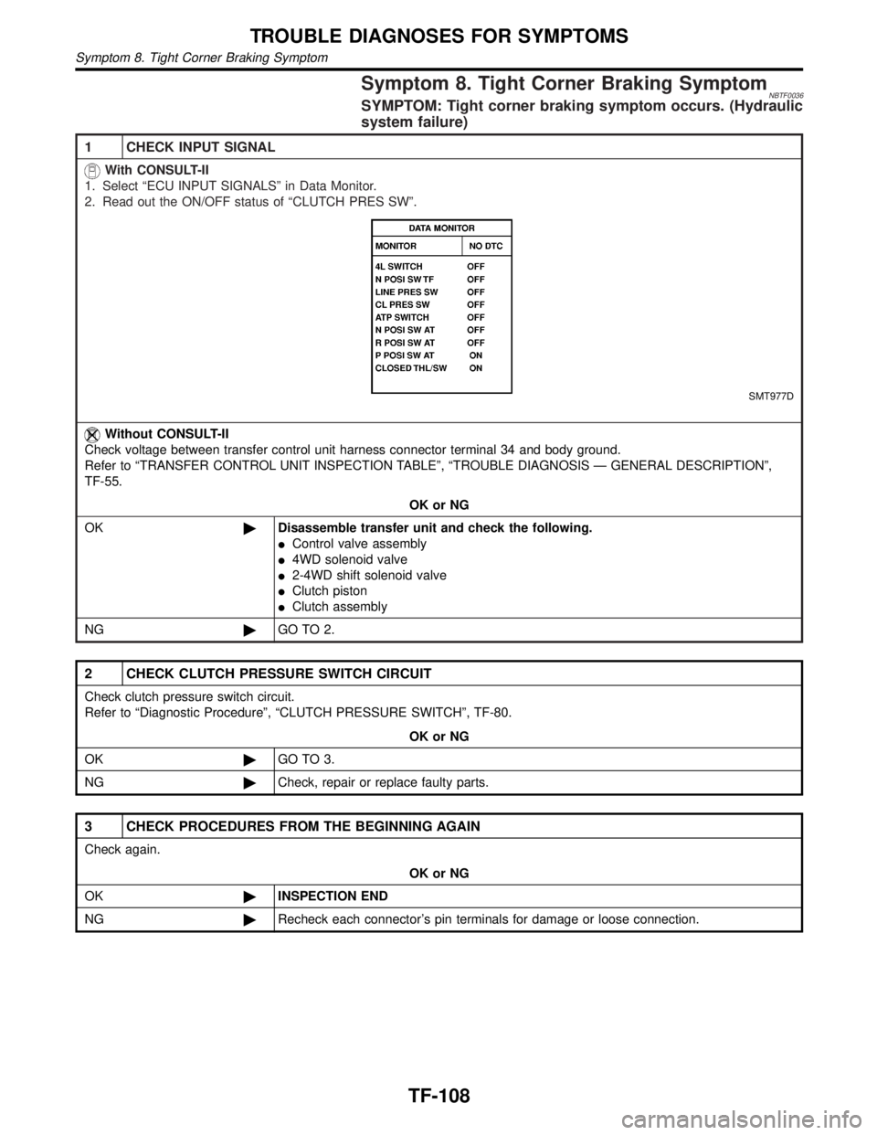
With CONSULT-II
1. Select ªECU INPUT SIGNALSº in Data Monitor.
2. Read out the ON/OFF status of ªATP SWº, ªNEUTRAL SWº and ªWAIT DETCT SWº.
SMT976D
OK or NG
OK©GO TO 6.
NG©Check the following.
IHarness continuity between transfer switch assembly sub-harness connector and
transfer control unit
IContinuity between transfer switch assembly sub-harness connector and body ground
GI
MA
EM
LC
EC
FE
AT
PD
AX
SU
BR
ST
RS
BT
HA
SC
EL
IDX
ATP SWITCH, WAIT DETECTION SWITCH AND NEUTRAL-4LO SWITCH
Diagnostic Procedure (Cont'd)
TF-77
Page 2316 of 2395
5 CHECK INPUT SIGNAL
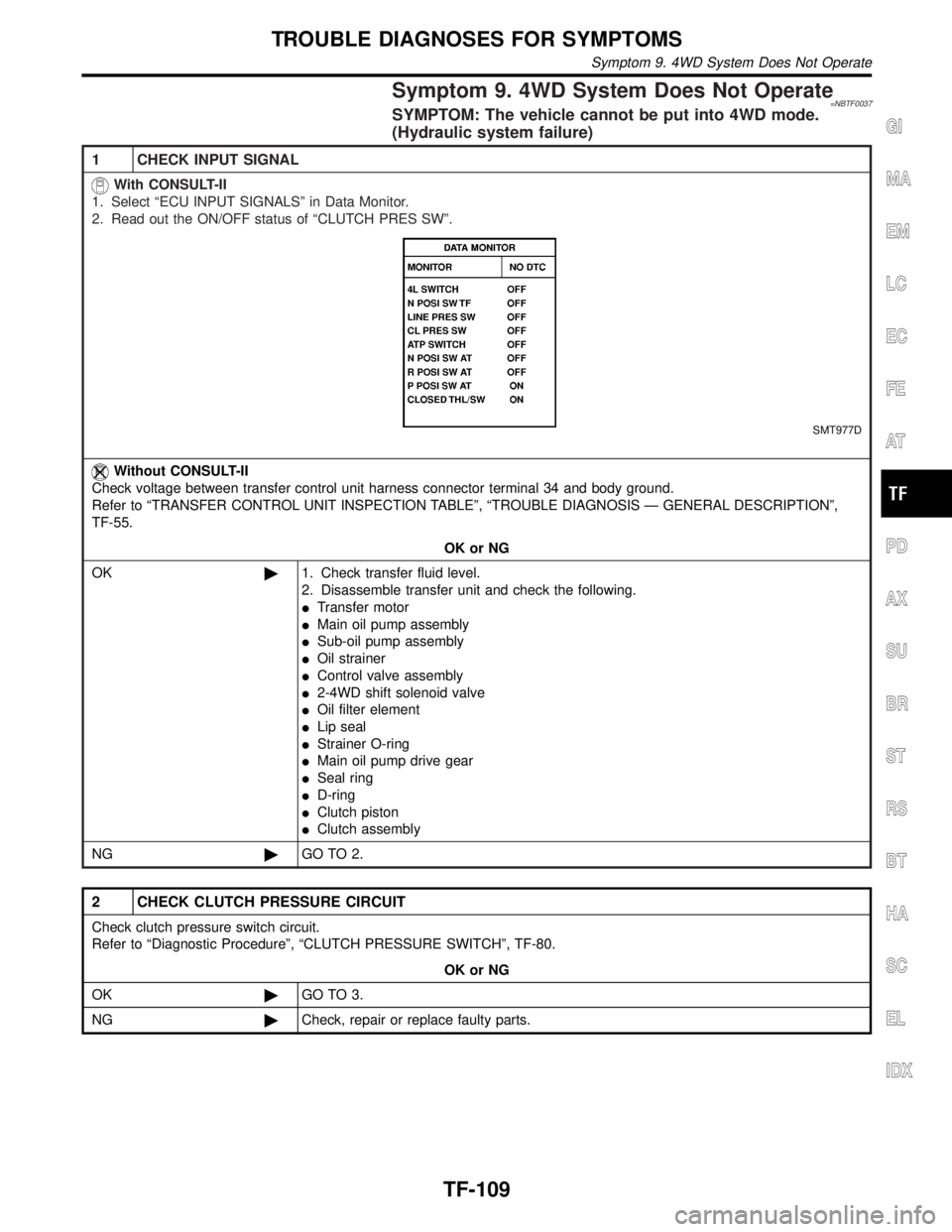
With CONSULT-II
1. Turn ignition switch to ªONº position.
2. Select ªECU INPUT SIGNALSº in Data Monitor.
3. Read out ON/OFF status of ªCL PRES SWº.
SMT788D
SMT977D
OK or NG
OK©GO TO 7.
NG©Check the following.
IContinuity between transfer control unit and transfer terminal cord assembly sub-har-
ness connector
ITransfer sub-harness
IClutch pressure switch
Refer to ª4WD Solenoid Valve, Clutch Pressure Switch and Line Pressure Switchº,
ªCOMPONENT INSPECTIONº, TF-111.
GI
MA
EM
LC
EC
FE
AT
PD
AX
SU
BR
ST
RS
BT
HA
SC
EL
IDX
CLUTCH PRESSURE SWITCH
Diagnostic Procedure (Cont'd)
TF-81
Page 2319 of 2395
4 CHECK INPUT SIGNAL
SMT790D
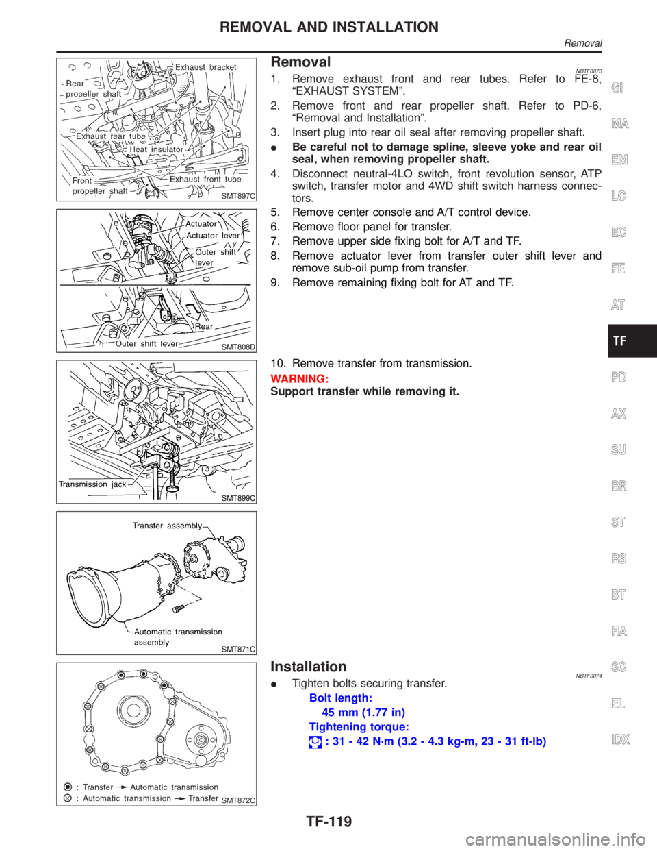
With CONSULT-II
1. Select ªECU INPUT SIGNALSº in Data Monitor.
2. Read out the ON/OFF status of ªLINE PRES SWº.
SMT977D
OK or NG
OK©GO TO 6.
NG©Check the following.
IContinuity between transfer control unit and transfer terminal cord assembly sub-har-
ness connector
ITransfer sub-harness
ILine pressure switch
Refer to ª4WD Solenoid Valve, Clutch Pressure Switch and Line Pressure Switchº,
ªCOMPONENT INSPECTIONº, TF-111.
LINE PRESSURE SWITCH
Diagnostic Procedure (Cont'd)
TF-84
Page 2343 of 2395

Symptom 8. Tight Corner Braking SymptomNBTF0036SYMPTOM: Tight corner braking symptom occurs. (Hydraulic
system failure)
1 CHECK INPUT SIGNAL
With CONSULT-II
1. Select ªECU INPUT SIGNALSº in Data Monitor.
2. Read out the ON/OFF status of ªCLUTCH PRES SWº.
SMT977D
Without CONSULT-II
Check voltage between transfer control unit harness connector terminal 34 and body ground.
Refer to ªTRANSFER CONTROL UNIT INSPECTION TABLEº, ªTROUBLE DIAGNOSIS Ð GENERAL DESCRIPTIONº,
TF-55.
OK or NG
OK©Disassemble transfer unit and check the following.
IControl valve assembly
I4WD solenoid valve
I2-4WD shift solenoid valve
IClutch piston
IClutch assembly
NG©GO TO 2.
2 CHECK CLUTCH PRESSURE SWITCH CIRCUIT
Check clutch pressure switch circuit.
Refer to ªDiagnostic Procedureº, ªCLUTCH PRESSURE SWITCHº, TF-80.
OK or NG
OK©GO TO 3.
NG©Check, repair or replace faulty parts.
3 CHECK PROCEDURES FROM THE BEGINNING AGAIN
Check again.
OK or NG
OK©INSPECTION END
NG©Recheck each connector's pin terminals for damage or loose connection.
TROUBLE DIAGNOSES FOR SYMPTOMS
Symptom 8. Tight Corner Braking Symptom
TF-108
Page 2344 of 2395

Symptom 9. 4WD System Does Not Operate=NBTF0037SYMPTOM: The vehicle cannot be put into 4WD mode.
(Hydraulic system failure)
1 CHECK INPUT SIGNAL
With CONSULT-II
1. Select ªECU INPUT SIGNALSº in Data Monitor.
2. Read out the ON/OFF status of ªCLUTCH PRES SWº.
SMT977D
Without CONSULT-II
Check voltage between transfer control unit harness connector terminal 34 and body ground.
Refer to ªTRANSFER CONTROL UNIT INSPECTION TABLEº, ªTROUBLE DIAGNOSIS Ð GENERAL DESCRIPTIONº,
TF-55.
OK or NG
OK©1. Check transfer fluid level.
2. Disassemble transfer unit and check the following.
ITransfer motor
IMain oil pump assembly
ISub-oil pump assembly
IOil strainer
IControl valve assembly
I2-4WD shift solenoid valve
IOil filter element
ILip seal
IStrainer O-ring
IMain oil pump drive gear
ISeal ring
ID-ring
IClutch piston
IClutch assembly
NG©GO TO 2.
2 CHECK CLUTCH PRESSURE CIRCUIT
Check clutch pressure switch circuit.
Refer to ªDiagnostic Procedureº, ªCLUTCH PRESSURE SWITCHº, TF-80.
OK or NG
OK©GO TO 3.
NG©Check, repair or replace faulty parts.
GI
MA
EM
LC
EC
FE
AT
PD
AX
SU
BR
ST
RS
BT
HA
SC
EL
IDX
TROUBLE DIAGNOSES FOR SYMPTOMS
Symptom 9. 4WD System Does Not Operate
TF-109
Page 2354 of 2395

SMT897C
RemovalNBTF00731. Remove exhaust front and rear tubes. Refer to FE-8,
ªEXHAUST SYSTEMº.
2. Remove front and rear propeller shaft. Refer to PD-6,
ªRemoval and Installationº.
3. Insert plug into rear oil seal after removing propeller shaft.
IBe careful not to damage spline, sleeve yoke and rear oil
seal, when removing propeller shaft.
4. Disconnect neutral-4LO switch, front revolution sensor, ATP
switch, transfer motor and 4WD shift switch harness connec-
tors.
SMT808D
5. Remove center console and A/T control device.
6. Remove floor panel for transfer.
7. Remove upper side fixing bolt for A/T and TF.
8. Remove actuator lever from transfer outer shift lever and
remove sub-oil pump from transfer.
9. Remove remaining fixing bolt for AT and TF.
SMT899C
SMT871C
10. Remove transfer from transmission.
WARNING:
Support transfer while removing it.
SMT872C
InstallationNBTF0074ITighten bolts securing transfer.
Bolt length:
45 mm (1.77 in)
Tightening torque:
: 31 - 42 N´m (3.2 - 4.3 kg-m, 23 - 31 ft-lb)
GI
MA
EM
LC
EC
FE
AT
PD
AX
SU
BR
ST
RS
BT
HA
SC
EL
IDX
REMOVAL AND INSTALLATION
Removal
TF-119
Page 2365 of 2395
SMT924C
7. Remove 4WD solenoid valve, clutch pressure switch, 2-4WD
shift solenoid valve, line pressure switch, and transfer fluid
temperature sensor from control valve assembly.
8. Remove O-rings from each solenoid valve, switch and termi-
nal body.
IDo not reuse O-rings.
SMT925C
9. Place control valve with lower body facing up, remove two
mounting bolts, and then remove lower body and separator
plate from upper body.
CAUTION:
IBe careful not to drop relief balls. Detach lower body care-
fully.
IDo not reuse separator plate.
SMT926C
10. Make sure reverse balls, relief balls and relief springs, accu-
mulator pistons, valve springs, and filters are securely installed
as shown in the figure, and remove them.
SMT927C
11. Remove retainer plates.
SMT928CA
12. Remove each control valve, spring and plug.
DISASSEMBLY
Center Case (Cont'd)
TF-130
Page 2376 of 2395
SMT011D
Front Case
ASSEMBLYNBTF0082Planetary Carrier, Sun Gear and Internal GearNBTF0082S011. Apply ATF to oil seal periphery, and install oil seal so that it is
flush with the end face of front case.
IDo not reuse oil seal.
SMT012D
2. Install internal gear with its groove facing snap ring into front
case. Then secure it with snap ring.
IDo not reuse snap ring.
SMT108D
3. Remove all the liquid gasket on plug bolt and front case. Apply
locking sealant to plug bolt, install it to front case and tighten
it to specified torque.
IWith one crest of plug bolt inserted in the hole, apply liquid
gasket 1215 to the thread.
: 19 - 25 N´m (1.9 - 2.5 kg-m, 14 - 18 ft-lb)
SMT014D
4. Install snap ring to main gear bearing.
IDo not reuse snap rings.
SMT015D
5. Set main gear bearing to front case, then press it.
GI
MA
EM
LC
EC
FE
AT
PD
AX
SU
BR
ST
RS
BT
HA
SC
EL
IDX
ASSEMBLY
Front Case
TF-141