Page 2202 of 2395

SST468C
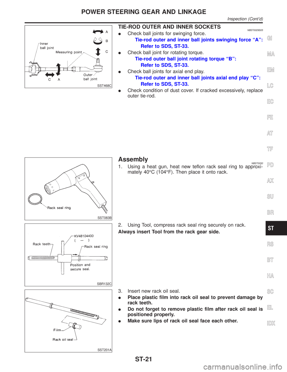
TIE-ROD OUTER AND INNER SOCKETSNBST0029S05ICheck ball joints for swinging force.
Tie-rod outer and inner ball joints swinging force ªAº:
Refer to SDS, ST-33.
ICheck ball joint for rotating torque.
Tie-rod outer ball joint rotating torque ªBº:
Refer to SDS, ST-33.
ICheck ball joints for axial end play.
Tie-rod outer and inner ball joints axial end play ªCº:
Refer to SDS, ST-33.
ICheck condition of dust cover. If cracked excessively, replace
outer tie-rod.
SST083B
AssemblyNBST00301. Using a heat gun, heat new teflon rack seal ring to approxi-
mately 40ÉC (104ÉF). Then place it onto rack.
SBR132C
2. Using Tool, compress rack seal ring securely on rack.
Always insert Tool from the rack gear side.
SST201A
3. Insert new rack oil seal.
IPlace plastic film into rack oil seal to prevent damage by
rack teeth.
IDo not forget to remove plastic film after rack oil seal is
positioned properly.
IMake sure lips of rack oil seal face each other.
GI
MA
EM
LC
EC
FE
AT
TF
PD
AX
SU
BR
RS
BT
HA
SC
EL
IDX
POWER STEERING GEAR AND LINKAGE
Inspection (Cont'd)
ST-21
Page 2212 of 2395

SST933C
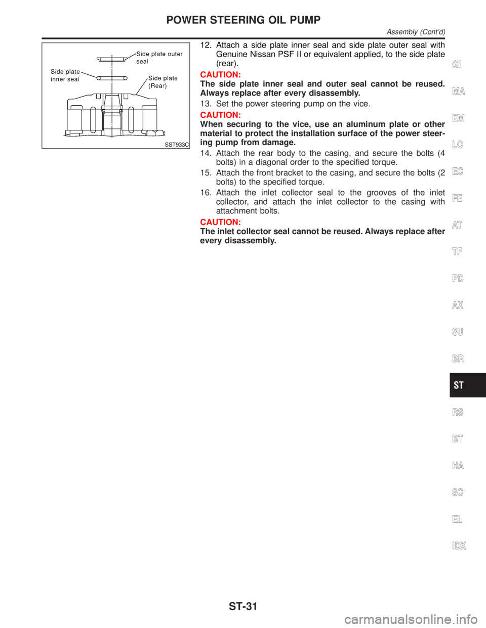
12. Attach a side plate inner seal and side plate outer seal with
Genuine Nissan PSF II or equivalent applied, to the side plate
(rear).
CAUTION:
The side plate inner seal and outer seal cannot be reused.
Always replace after every disassembly.
13. Set the power steering pump on the vice.
CAUTION:
When securing to the vice, use an aluminum plate or other
material to protect the installation surface of the power steer-
ing pump from damage.
14. Attach the rear body to the casing, and secure the bolts (4
bolts) in a diagonal order to the specified torque.
15. Attach the front bracket to the casing, and secure the bolts (2
bolts) to the specified torque.
16. Attach the inlet collector seal to the grooves of the inlet
collector, and attach the inlet collector to the casing with
attachment bolts.
CAUTION:
The inlet collector seal cannot be reused. Always replace after
every disassembly.
GI
MA
EM
LC
EC
FE
AT
TF
PD
AX
SU
BR
RS
BT
HA
SC
EL
IDX
POWER STEERING OIL PUMP
Assembly (Cont'd)
ST-31
Page 2268 of 2395
SMT962D
DATA MONITORNBTF0012S03CONSULT-II Setting ProcedureNBTF0012S03011. Turn ignition switch to ªOFFº position.
2. Connect CONSULT-II to data link connector, which is located
in instrument lower panel on driver side.
3. Turn ignition switch to ªONº position.
4. Touch ªSTARTº.
SMT964D
5. Touch ªALL MODE 4WDº.
SMT965D
6. Touch ªDATA MONITORº.
SAT972J
7. Touch ªECU INPUT SIGNALSº or ªMAIN SIGNALSº.
8. Select ªNumerical Displayº, ªBar Chart Displayº or ªLine Graph
Displayº.
9. Touch ªSETTINGº to set record conditions.
SAT973J
10. Touch ªAUTO TRIGº or ªMANU TRIGº.
11. Return to ªSELECT MONITOR ITEMº on ªDATA MONITORº
screen and touch ªSTARTº.
GI
MA
EM
LC
EC
FE
AT
PD
AX
SU
BR
ST
RS
BT
HA
SC
EL
IDX
ON BOARD DIAGNOSTIC SYSTEM DESCRIPTION
Trouble Diagnosis with CONSULT-II (Cont'd)
TF-33
Page 2269 of 2395
![INFINITI QX4 2001 Factory Service Manual SMT963D
12. Monitored data are displayed.
DATA MONITOR ITEMSNBTF0012S04q: StandardH: Option
Item [Unit]Monitor item
Remarks
ECU input
signalsMain sig-
nalsItem menu
selection
Revolution sensor-front [ INFINITI QX4 2001 Factory Service Manual SMT963D
12. Monitored data are displayed.
DATA MONITOR ITEMSNBTF0012S04q: StandardH: Option
Item [Unit]Monitor item
Remarks
ECU input
signalsMain sig-
nalsItem menu
selection
Revolution sensor-front [](/manual-img/42/57027/w960_57027-2268.png)
SMT963D
12. Monitored data are displayed.
DATA MONITOR ITEMSNBTF0012S04q: StandardH: Option
Item [Unit]Monitor item
Remarks
ECU input
signalsMain sig-
nalsItem menu
selection
Revolution sensor-front [km/h (MPH)]qHRevolution sensor installed on T/F
Revolution sensor-rear [km/h (MPH)]qHVehicle speed sensor´A/T
Engine speed [rpm]qH
Throttle position sensor [V]qH
Transfer fluid temperature sensor [V]qH
Battery voltage [V]qH
2WD switch [ON-OFF]qH2WD switch of 4WD shift switch
AUTO switch [ON-OFF]qHAUTO switch of 4WD shift switch
Lock switch [ON-OFF]qH4H switch of 4WD shift switch
4L switch [ON-OFF]qH4LO switch of 4WD shift switch
N position switch TF [ON-OFF]qHN position switch of transfer
Line pressure switch [ON-OFF]qHLine pressure switch
Clutch pressure switch [ON-OFF]qHClutch pressure switch
ATP switch [ON-OFF]qH
N position switch [ON-OFF]qHªNº position on A/T PNP switch
R position switch [ON-OFF]qHªRº position on A/T PNP switch
P position switch [ON-OFF]qHªPº position on A/T PNP switch
Closed throttle position switch
[ON/OFF]qHIdle contact of throttle position switch
ABS operation switch [ON-OFF]qHABS operation switch
Wait detection switch [ON-OFF]qH
Throttle openingqHThrottle opening recognized by transfer control
unit
4WD-modeqH4WD-mode recognized by transfer control unit
(2W, AUTO, 4H & 4LO)
Vehicle speed comp [km/h (MPH)]qHVehicle speed recognized by transfer control
unit
*Control torque [N´m (kg-m, ft-lb)]qHCalculated torque recognized by transfer control
unit
ON BOARD DIAGNOSTIC SYSTEM DESCRIPTION
Trouble Diagnosis with CONSULT-II (Cont'd)
TF-34
Page 2270 of 2395
![INFINITI QX4 2001 Factory Service Manual Item [Unit]Monitor item
Remarks
ECU input
signalsMain sig-
nalsItem menu
selection
Duty solenoid valve [%]
(Transfer 4WD solenoid valve)qH
2-4WD shift solenoid valve [ON-OFF]qH
Control signal outputs INFINITI QX4 2001 Factory Service Manual Item [Unit]Monitor item
Remarks
ECU input
signalsMain sig-
nalsItem menu
selection
Duty solenoid valve [%]
(Transfer 4WD solenoid valve)qH
2-4WD shift solenoid valve [ON-OFF]qH
Control signal outputs](/manual-img/42/57027/w960_57027-2269.png)
Item [Unit]Monitor item
Remarks
ECU input
signalsMain sig-
nalsItem menu
selection
Duty solenoid valve [%]
(Transfer 4WD solenoid valve)qH
2-4WD shift solenoid valve [ON-OFF]qH
Control signal outputs of transfer control unit Transfer motor relay [ON-OFF]qH
Shift activating 1 [ON-OFF]qH
Shift activating 2 [ON-OFF]qH
2-4WD shift solenoid valve monitor
[ON-OFF]H
Check signal (re-input signal) of transfer control
unit control signal output is displayed. If circuit
is shorted or open, ON/OFF state does not
change. Transfer motor relay monitor [ON-OFF]H
Shift activating monitor 1 [ON-OFF]H
Shift activating monitor 2 [ON-OFF]H
4WD fail lamp [ON-OFF]qHTransfer control unit control signal output for
4WD warning lamp (left)
Shift position switch 1 [ON-OFF]qH
Shift position switch 2 [ON-OFF]qH
2WD indicator lamp [ON-OFF]HTransfer control unit control signal output for
4WD shift indicator lamp (rear)
AUTO indicator lamp [ON-OFF]HTransfer control unit control signal output for
4WD shift indicator lamp (front & rear)
LOCK indicator lamp [ON-OFF]HTransfer control unit control signal output for
4WD shift indicator lamp (center)
4LO indicator lamp [ON-OFF]HTransfer control unit control signal output for
4WD shift indicator lamp (right)
Offset at startingHAppears on monitor but does not function.
Clutch limit [N´m (kg-m, ft-lb)]HClutch force release limit value set in WORK
SUPPORT
Voltage [V]HValue measured by voltage probe is displayed.
Frequency [Hz]HValue measured by pulse probe is displayed. If
measurement is impossible, ª#º sign is dis-
played. ª#º sign is also displayed at the final
data value until the measurement result is
obtained.
DUTY-HIH
Duty cycle value for measurement probe is dis-
played.
DUTY-LOWH
PLS WIDTH-HIH
Measured pulse width of measurement probe is
displayed.
PLS WIDTH-LOWH
*: This item is indicated as ªCOMP CL TORQº.GI
MA
EM
LC
EC
FE
AT
PD
AX
SU
BR
ST
RS
BT
HA
SC
EL
IDX
ON BOARD DIAGNOSTIC SYSTEM DESCRIPTION
Trouble Diagnosis with CONSULT-II (Cont'd)
TF-35
Page 2297 of 2395
4 CHECK INPUT SIGNAL
With CONSULT-II
1. Start engine.
2. Select ªECU INPUT SIGNALSº in Data Monitor.
3. Read out the value of ªVEHICLE SPEED SENSOR (FRONT)º while driving.
SMT773D
SMT974D
4. Check if the value changes according to accelerating and decelerating the vehicle.
OK or NG
OK©GO TO 6.
NG©GO TO 7.
VEHICLE SPEED SENSOR (FRONT REVOLUTION SENSOR)
Diagnostic Procedure (Cont'd)
TF-62
Page 2302 of 2395
2 CHECK INPUT SIGNAL
With CONSULT-II
1. Select ªECU INPUT SIGNALSº in Data Monitor.
2. Read out ON/OFF status of ª2WD SWº and ªLOCK SWITCHº.
SMT974D
OK or NG
OK©1. Perform transfer control unit input/output signal inspection. Refer to ªTRANSFER
CONTROL UNIT INSPECTION TABLEº, ªTROUBLE DIAGNOSIS Ð GENERAL
DESCRIPTIONº, TF-55.
2. If NG, recheck transfer control unit pin terminals for damage or loose connection with
harness connector.
NG©GO TO 3.
GI
MA
EM
LC
EC
FE
AT
PD
AX
SU
BR
ST
RS
BT
HA
SC
EL
IDX
2-4WD SHIFT SOLENOID VALVE AND 4WD SHIFT SWITCH
Diagnostic Procedure (Cont'd)
TF-67
Page 2309 of 2395
4 CHECK INPUT SIGNAL
SMT784D
With CONSULT-II
1. Start engine.
2. Select ªECU INPUT SIGNALSº in Data Monitor.
3. Read out the value of ªFLUID TEMP SEº.
Voltage:
20ÉC (68ÉF): Approx. 1.5V
80ÉC (176ÉF): Approx. 0.5V
SMT974D
OK or NG
OK©GO TO 6.
NG©Check the following.
IContinuity between transfer control unit and transfer terminal cord assembly sub-har-
ness connector
TRANSFER FLUID TEMPERATURE SENSOR
Diagnostic Procedure (Cont'd)
TF-74